SANtricity
®
ES Storage
Manager
Concepts Guide for Version 10.70
SANtricity ES Storage Manager Concepts Guide for Version 10.70 iii
Contents
C
HAPTER1: S
TORINGY
OURD
ATAStorage Arrays ...1-1 Storage Area Networks...1-1 Management Methods...1-2 Out-of-Band Management ...1-2 In-Band Management...1-2 RAID Levels and Data Redundancy...1-3 Dynamic RAID-Level Migration...1-3 RAID Level Configuration Table...1-4 Hardware Redundancy...1-6 Controller Cache Memory...1-7 Tray Loss Protection...1-8 Drawer Loss Protection...1-8 Hot Spare Drives... 1-10 Channel Protection... 1-11 I/O Data Path Protection... 1-11 Multi-Path Driver with AVT Enabled ... 1-11 Multi-Path Driver with AVT Disabled ... 1-12 Target Port Group Support... 1-12 Load Balancing... 1-12 Round Robin with Subset ... 1-13 Least Queue Depth with Subset... 1-13 Least Path Weight with Subset ... 1-13
C
HAPTER2: I
NTRODUCINGTHES
TORAGEM
ANAGEMENTS
OFTWAREEnterprise Management Window ...2-1 Parts of the Enterprise Management Window ...2-2
EMW Devices Tab...2-2 Tree View ...2-3 Table View ...2-4 Showing Managed Storage Arrays in the Table View ...2-4 EMW Setup Tab ...2-5 Array Management Window...2-5 Starting the Array Management Window...2-6 Parts of the Array Management Window...2-6 Title Bar ...2-6 Menu Bar ...2-6 Toolbar ...2-6 Storage Array Name ...2-6 Tabs ...2-7 Status Bar ...2-8 Summary Tab ...2-8 Logical Tab ...2-8 Logical Pane ...2-8 Nodes in the Logical Pane ...2-9 Types of Volumes ...2-9 Properties Pane ... 2-10 Physical Tab ... 2-10 Controller Status ... 2-11 View Tray Components ... 2-11 Drive Trays ... 2-12 Show Drives List ... 2-12 Mappings Tab... 2-12 Topology Pane ... 2-13 Nodes in the Topology Pane ... 2-13 Storage Partition Icon ... 2-14 Defined Mappings Pane ... 2-14 AMW Setup Tab... 2-15 Support Tab ... 2-15 Managing Multiple Software Versions ... 2-16
SANtricity ES Storage Manager Concepts Guide for Version 10.70 v
C
HAPTER3: C
ONFIGURINGTHES
TORAGEA
RRAYSVolumes and Volume Groups ...3-1 Standard Volumes ...3-1 Volume Groups ...3-2 Volume Group Creation...3-3 Specifying Volume Parameters ...3-4 Dynamic Capacity Expansion ...3-5 Register the Volume with the Operating System...3-6 Premium Features ...3-6 SANshare Storage Partitioning ...3-7 Snapshot Volume Premium Feature...3-8 Creating Snapshot Volumes ...3-8 Discontinuing the Use of a Snapshot Volume ...3-9 Disabling and Restarting Multiple Snapshots ...3-9 Dynamic Volume Expansion ... 3-10 Remote Volume Mirroring Premium Feature ... 3-10 Primary Volumes and Secondary Volumes ... 3-11 Mirror Repository Volumes ... 3-12 Data Replication ... 3-12 Write Modes ... 3-12 Volume Copy Premium Feature ... 3-14 Source Volumes ... 3-15 Target Volume ... 3-15 Creating a Volume Copy ... 3-15 SafeStore Drive Security and SafeStore Enterprise Key Manager... 3-16 Creating a Security Key ... 3-18 Changing a Security Key ... 3-19 Saving a Security Key ... 3-19 Using SafeStore Enterprise Key Manager ... 3-20 Unlocking Secure Drives ... 3-20 Validating the Security Key ... 3-21
Solid State Disks ... 3-21 Identifying SSDs ... 3-22 Creating Volume Groups ... 3-22 Wear Life ... 3-22 Write Caching ... 3-23 Background Media Scans ... 3-23 Heterogeneous Hosts ... 3-23 Password Protection ... 3-23 Persistent Reservations Management ... 3-24 HotScale Technology... 3-25
C
HAPTER4: M
AINTAININGANDM
ONITORINGS
TORAGEA
RRAYSStorage Array Health...4-1 Background Media Scan...4-1 Event Monitor...4-2 Alert Notifications...4-3 Configuring Alert Notifications...4-3 Customer Support Alert Notifications...4-4 Upgrading the Controller Firmware...4-4 Monitoring the Status of the Download...4-7 Problem Notification...4-9 Storage Array Problem Recovery ...4-9 Recovery Guru ... 4-10
SANtricity ES Storage Manager Concepts Guide for Version 10.70 vii
List of Figures
C
HAPTER3: C
ONFIGURINGTHES
TORAGEA
RRAYSFigure 3–1. Configuring a Storage Array ... 3-4
C
HAPTER4: M
AINTAININGANDM
ONITORINGS
TORAGEA
RRAYSFigure 4–1. Event Monitor Configuration ... 4-3 Figure 4–2. Recovery Guru Window Example ... 4-10
List of Tables
C
HAPTER1: S
TORINGY
OURD
ATATable 1–1. RAID Level Configurations ... 1-4 Table 1–2. Load-Balancing Policies That Are Supported by the Operating Systems ... 1-13
C
HAPTER2: I
NTRODUCINGTHES
TORAGEM
ANAGEMENTS
OFTWARETable 2–1. Parts of the Enterprise Management Window ... 2-2
C
HAPTER3: C
ONFIGURINGTHES
TORAGEA
RRAYSTable 3–1. Maximum Number of Volumes Allowed ... 3-2 Table 3–2. Volume Parameters for Free Capacity, Unconfigured Capacity, and
Unassigned Drives ... 3-4 Table 3–3. Storage Partitions Supported by the Storage Array ... 3-7 Table 3–4. Maximum Number of Snapshots Supported by the Storage Array ... 3-8 Table 3–5. Maximum Number of Defined Mirrors Allowed by the Storage Array ... 3-10 Table 3–6. Maximum Number of Volume Copies Supported by the Storage Array ... 3-14 Table 3–7. Volume Group Security Properties ... 3-17
SANtricity ES Storage Manager Concepts Guide for Version 10.70 xi
Document Conventions
Definitions of Safety Notices
DANGER Indicates an imminently hazardous situation that will result in death or severe personal injury.
WARNING Indicates a potentially hazardous situation that could result in death or severe personal injury.
CAUTION Indicates a potentially hazardous situation that could result in moderate or minor personal injury.
Definitions of Informational Notices
ATTENTION Indicates a potentially hazardous situation that could result in data loss (or other interruption) or equipment damage.
IMPORTANT Indicates information or criteria that is necessary to perform a procedure correctly.
Typographic Conventions
Italic indicates the title of documents, emphasized words, and new terms.
Bold indicates choices in procedures and other emphasized text. Bold also indicates menu selections and user-interface controls, such as buttons and key names.
Monospace indicates arguments, code examples, code phrases, command-line text, directories, error messages, file names, folders, on-screen text, parameters, Universal Resource Locators (URLs), and user input.
Monospace italic indicates placeholders and variables in code.
SANtricity ES Storage Manager Concepts Guide for Version 10.70 xiii
About This Document
This document provides the conceptual framework necessary to understand the features and functions of the SANtricity® ES Storage Manager software. This document describes the basic software layout and introduces software concepts. This document also provides information about storage array configuration options, the functions of the storage management software, and how to monitor storage arrays.
Intended Readers
This document is intended for purchasers, end users, system operators, system administrators, and service personnel who operate, maintain, and troubleshoot the SANtricity ES Storage Manager software. Readers must be familiar with computer system operation, maintenance, and repair. In addition, they should understand storage array, Redundant Array of Independent Disks (RAID), and network technologies.
Related Publications
These documents contain additional information about the SANtricity ES Storage Manager software.
•
The online help topics in SANtricity ES Storage Manager•
Product Release Notes for SANtricity ES Storage Manager Version 10.70•
SANtricity ES Storage Manager Command Line Interface and Script Commands Programming Guide for Version 10.70•
SANtricity ES Storage Manager Remote Volume Mirroring Feature Guide for Version 10.1x•
SANtricity ES Storage Manager Volume Copy Feature Guide for Version 10.1xWeb Address
For information about products mentioned in this document, go to:
Chapter
1
Storing Your Data
Storage Arrays
A storage array has redundant components, including drives, controllers, power supplies, and fans. These redundant components keep the storage array operational if a single component fails.
The storage array configuration provides a secure and robust system with which to store large amounts of data and allows for a variety of backup and retrieval scenarios. Administrators can set up the storage management software to maintain a specific level of security and configuration on the storage area network, such that the network requires little human interaction to perform its daily functions.
For additional information and detailed procedures for the options described in this chapter, refer to the Learn About Data Protection Strategies online help topic in the Array Management Window of SANtricity ES Storage Manager.
Storage Area Networks
A storage area network (SAN) transfers data between computers and storage systems and is managed by the SANtricity ES Storage Manager software. A SAN includes one or more storage arrays that are managed by one or more servers or hosts running the storage management software. Use this software to add, monitor, manage, and remove the storage devices on your SAN.
Within the storage management software, you can configure the data to be stored in a particular configuration over a series of physical storage components and logical (virtual) storage components.
NOTE The SANtricity ES Storage Manager software is also referred to as the storage management software.
Storing Your Data . . . .
1-2 SANtricity ES Storage Manager Concepts Guide for Version 10.70 Data and management instructions are sent from a host to the storage arrays using the storage array controllers. When the data reaches the storage array, the controllers allocate the data across a series of drives, which are mounted in trays. The controllers use the data configuration specified by the RAID level selected in the storage
management software.
The SAN can also include storage management stations, which also run the storage management software. A storage management station manages the storage arrays but does not send data to them. Although physical storage array configurations vary, all SANs work using these basic principles.
Management Methods
Depending on your system configuration, you can use an out-of-band management method, an in-band management method, or both to manage a storage array controller from a storage management station or host.
IMPORTANT A maximum of eight storage management stations can concurrently
monitor an out-of-band managed storage array. This limit does not apply to systems that manage the storage array through the in-band management method.
Out-of-Band Management
You can use the out-of-band management method to manage a storage array directly over the network through an Ethernet connection, from a storage management station to the controllers. This management method lets you configure the maximum number of volumes that are supported by your operating system and host adapters.
IMPORTANT Storage management stations require Transmission Control Protocol/
Internet Protocol (TCP/IP) to support the out-of-band management of storage arrays.
In-Band Management
You can use the in-band management method to manage a storage array in which the controllers are managed through an Ethernet connection from a storage management station to a host that is running host-agent software. The host-agent software receives communication from the storage management client software and passes it to the storage array controllers along a Fibre Channel I/O path. The controllers also use the I/O connections to send event information back to the storage management station through the host.
. . . RAID Levels and Data Redundancy
When you add storage arrays by using this management method, you must specify only the host name or IP address of the host. After you add the specific host name or IP address, the host-agent software automatically detects any storage arrays that are connected to that host.
NOTE Systems running desktop (non-server) Windows operating systems can be used only as storage management stations. You cannot use systems running desktop operating systems to run the host-agent software.
RAID Levels and Data Redundancy
RAID is an acronym for Redundant Array of Independent Disks. This storage solution stores the same data or information about the data (parity) in different places on multiple hard drives. Data can be written in parallel to multiple drives, which can improve performance. If a drive in a volume group fails, you can use the redundant data or parity data to regenerate the data on the replacement drive.
RAID relies on a series of configurations, called levels, to determine how user data and redundancy data are written to and retrieved from the drives. Each level provides different performance features and protection features. The storage management software offers six formal RAID level configurations: RAID Level 0, RAID Level 1, RAID Level 3, RAID Level 5, RAID Level 6, and RAID Level 10.
NOTE RAID Level 6 is a premium feature for the Xanadu-220 controller tray. You must enable RAID Level 6 with a feature key file.
RAID Level 1, RAID Level 3, RAID Level 5, RAID Level 6, and RAID Level 10 write
redundancy data to the drive media for fault tolerance. The redundancy data might be a copy of the data or an error-correcting code derived from the data. If a drive fails, the system can use the redundancy data to quickly reconstruct information.
You can configure only one RAID level across each volume group. Each volume group stores its own redundancy data. The capacity of the volume group is the aggregate capacity of the member drives, minus the capacity that is reserved for redundancy data. The amount of capacity needed for redundancy data depends on the RAID level used.
Dynamic RAID-Level Migration
Dynamic RAID-Level Migration (DRM) is a modification operation that lets you change the RAID level on a selected volume group. The volume group must contain sufficient free space and a permissible number of drives, or the DRM request is rejected.
Storing Your Data . . . .
1-4 SANtricity ES Storage Manager Concepts Guide for Version 10.70 During the migration process, you can continue to access data on volume groups, volumes, and drives in the storage management software. However, you cannot cancel the DRM operation after the process begins.
NOTE If you are using Dynamic RAID-Level Migration to migrate a volume group to RAID Level 6, you must enable RAID Level 6 with the feature key file before you start the Dynamic RAID-Level Migration.
RAID Level Configuration Table
Table 1–1 RAID Level Configurations
RAID Level Short Description Detailed Description RAID Level 0 Non-redundant, striping
mode
•
A minimum of one drive is required for RAID Level 0.•
RAID Level 0 can have more than 30 drives in avolume group.
•
You can use RAID Level 0 for high-performance needs, but it does not provide data redundancy.•
Data is striped across all of the drives in the volumegroup.
•
Do not use this RAID level for high data-availability needs. RAID Level 0 is better for non-critical data.•
A single drive failure causes all of the associated. . . RAID Levels and Data Redundancy
RAID Level 1 or RAID Level 10
Striping and mirroring mode
•
A minimum of two drives are required for RAID Level 1: one for the user data and one for the mirrored data. If you select four or more drives, RAID Level 10 is automatically configured across the volume group: two drives for the user data, and two drives for the mirrored data.•
RAID Level 1 and RAID Level 10 can have more than 30 drives in a volume group.•
RAID Level 1 and RAID Level 10 provide high performance and the best data availability. On a RAID Level 1 volume, data is written to two duplicate drives simultaneously. On a RAID Level 10 volume, data is striped across mirrored pairs.•
If one of the drives in a drive-pair fails, the system can instantly switch to the other drive without any loss of data or service.•
RAID Level 1 and RAID Level 10 use drive mirroring to make an exact copy from one drive to another.•
A single drive failure causes associated volumes tobecome degraded, but the mirror drive allows access to the data.
•
Two or more drive failures in a volume group cause all of the associated volumes to fail, and data loss could occur.RAID Level 3 High-bandwidth mode
•
A minimum of three drives is required for RAID Level 3.•
RAID Level 3 is limited to a maximum of 30 drives in a volume group.•
RAID Level 3 stripes both user data and redundancy data (parity) across the drives.•
RAID Level 3 uses the equivalent of the capacity of one drive (in a volume group) for redundancy data.•
RAID Level 3 is used for applications with large datatransfers, such as multimedia or medical imaging, that write and read large sequential chunks of data.
•
A single drive failure in a volume group causes theassociated volumes to become degraded, but the redundancy data allows access to the data.
•
Two or more drive failures in a volume group cause all of the associated volumes to fail, and data loss could occur.Storing Your Data . . . .
1-6 SANtricity ES Storage Manager Concepts Guide for Version 10.70
Hardware Redundancy
Data-protection strategies provided by the storage array hardware include controller cache memory, hot spare drives, background media scans, and channel protection.
RAID Level 5 High I/O mode
•
A minimum of three drives is required for RAID Level 5.•
RAID Level 5 is limited to a maximum of 30 drives in a volume group.•
RAID Level 5 stripes both user data and redundancy data (parity) across the drives.•
RAID Level 5 uses the equivalent of the capacity of one drive (in a volume group) for redundancy data.•
A single drive failure in a volume group causesassociated volumes to become degraded, but the redundancy data allows access to the data.
•
Two or more drive failures in a volume group cause all of the associated volumes to fail, and data loss could occur.RAID Level 6 High I/O mode with simultaneous drive failure protection
•
A minimum of five drives is required for RAID Level 6.•
RAID Level 6 is limited to a maximum of 30 drives in avolume group.
•
RAID Level 6 stripes both user data and redundancy data (parity) across the drives.•
RAID Level 6 uses the equivalent of the capacity of two drives (in a volume group) for redundancy data.•
RAID Level 6 protects against the simultaneousfailure of two volume group member drives by using two independent error-correction schemes.
•
RAID Level 6 is a premium feature for the CDE3992 controller-drive tray, the CDE3994 controller-drive tray, and the CE7900 controller tray. You must enable RAID Level 6 with a feature key file.. . . Hardware Redundancy
Controller Cache Memory
ATTENTION Possible loss of data access – Do not enable the Write caching without batteries parameter unless you have a uninterruptible power supply (UPS) for power loss protection. If you have the parameter enabled and your batteries are low or discharged, the data in the cache could be lost if a power outage occurs.
Write caching, or caching a drive segment to a memory buffer before writing to the drive, can increase I/O performance during data transfers. However, write caching also increases the risk of data loss if a controller (or its memory) fails while unwritten data resides in cache memory. Write-cache mirroring protects data during a controller-memory failure or a cache-controller-memory failure. When you enable write cache, cached data is mirrored across two redundant controllers with the same cache size. The data written to the cache memory of one controller is also written to the cache memory of the alternate controller. Therefore, if one controller fails, the alternate controller can complete all outstanding write operations.
To prevent data loss or corruption, the controller periodically writes cache data to a drive (flushes the cache) when the amount of unwritten data in the cache reaches a certain level, called a start percentage, or when data has been in the cache for a predetermined amount of time. The controller continues to write data to a drive until the amount of data in the cache drops to a stop percentage level. You can configure the start percentage and the stop percentage to suit your own storage requirements. For example, you can specify that the controller start flushing the cache when it reaches 80-percent full and stop flushing the cache when it reaches 16-percent full.
Low start percentages and low stop percentages provide for maximum data protection. However, choosing low start percentages and low stop percentages increases the chance that the data requested by a read command is not in the cache. This choice decreases the cache-hit percentage for writes and the I/O requests. Choosing low start percentages and low stop percentages also increases the number of drive transfers that are necessary to maintain the cache level. This choice increases system overhead and further decreases performance.
In case of power outages, data in the controller cache memory is protected. Controller trays and controller-drive trays contain batteries that protect the data in the cache by maintaining a level of power until the data can be written to the drive media or a flash memory card.
If the controller supports a flash memory card, the cache data can be written to the flash memory card when a power outage occurs. For example, the CDE2600 controller-drive tray supports a flash memory card to write the cache data. The battery is only needed to maintain power while the data in the cache is written to the flash memory card. The flash memory card provides nonvolatile backup of the cache data in case of long power outages. When power is restored to the controllers, the cache data can be read from the flash memory card.
Storing Your Data . . . .
1-8 SANtricity ES Storage Manager Concepts Guide for Version 10.70 If a power outage occurs, and there is no battery or the battery is damaged, data in the cache that has not been written to the drive media is lost. This situation occurs even if the data is mirrored to the cache memory of both controllers. It is, therefore, important to change the batteries in the controller tray and the controller-drive tray at the recommended time intervals. The controllers in the storage array keep track of the age (in days) of the battery. After you replace the battery, you might need to reset the age of the battery. Then you will receive an accurate critical alert notification when the battery is nearing expiration and when the battery has expired.
Tray Loss Protection
When you create a volume group using the tray loss protection feature, all of the drives in the volume group are found in different drive trays. Tray loss protection provides more data protection if access to the tray is lost. This feature is used by default when you choose the automatic configuration option.
Tray loss protection depends on the number of trays that are available and the value set for the Redundant Array of Independent Disks (RAID) level. Configuring your volume groups to have tray loss protection is recommended. If your configuration supports the minimum number of drive trays for your RAID level, create your volume groups to have tray loss protection.
Drawer Loss Protection
Drawer loss protection is a characteristic of a volume group.
In drive trays that contain drives in drawers, a drawer failure can lead to inaccessibility of data on the volumes in a volume group. A drawer might fail because of a loss of power, a failure of an environmental services monitor (ESM), or a failure of an internal component within the drawer.
RAID Level Criteria for Tray Loss Protection
RAID Level 0 No tray loss protection (RAID Level 0 does not
provide redundancy). RAID Level 1 or RAID
Level 10
For RAID Level 1, the volume group must use a minimum of two drives found in separate trays. For RAID Level 10, the volume group must use a minimum of four drives found in separate trays. RAID Level 3 The volume group must use a minimum of three
drives found in separate trays.
RAID Level 5 The volume group must use a minimum of three drives found in separate trays.
RAID Level 6 The volume group must use a minimum of five drives, with a maximum of two drives in any tray.
. . . Hardware Redundancy
The availability of drawer loss protection for a volume group is based on the location of the drives that comprise the volume group. In the event of a single drawer failure, data on the volumes in a volume group remains accessible if the volume group has drawer loss protection. If a drawer fails and the volume group is drawer loss protected, the volume group changes to Degraded status, and the data remains accessible.
To achieve drawer loss protection, the drives that comprise a volume group must be located in different drawers with respect to their RAID levels as shown in this table.
•
Mirror pair 1 = Drive in tray 1, drawer 1, slot 1, and drive in tray 1, drawer 2, slot 1•
Mirror pair 2 = Drive in tray 1, drawer 1, slot 2, and drive in tray 1, drawer 2, slot 2•
Mirror pair 3 = Drive in tray 1, drawer 1, slot 3, and drive in tray 2, drawer 2, slot 3RAID Level Criteria for Drawer Loss Protection
RAID Level 3 and RAID Level 5
RAID Level 3 and RAID Level 5 require a minimum of three drives. Place all of the drives in different drawers for a RAID Level 3 volume group and for a RAID Level 5 volume group to achieve drawer loss protection. Drawer loss protection cannot be achieved for RAID Level 3 and RAID Level 5 if more than one drive is placed in the same drawer.
RAID Level 6 RAID Level 6 requires a minimum of five drives. Place all of the drives in different drawers or place a maximum of two drives in the same drawer and the remaining drives in different drawers to achieve drawer loss protection for a RAID Level 6 volume group.
RAID Level 1 and RAID Level 10
RAID Level 1 requires a minimum of two drives. Make sure that each drive in a mirrored pair is located in a different drawer.
If you make sure that each drive in a mirrored pair is located in a different drawer, you can have more than two drives of the volume group within the same drawer. For example, if you create a RAID Level 1 volume group with six drives (three mirrored pairs), you can achieve the drawer loss protection for the volume group with only two drawers as shown in this example:
Six-drive RAID Level 1 volume group:
RAID Level 10 requires a minimum of four drives. Make sure that each drive in a mirrored pair is located in a different drawer.
RAID Level 0 You cannot achieve drawer loss protection because the RAID Level 0 volume group does not have redundancy.
Storing Your Data . . . .
1-10 SANtricity ES Storage Manager Concepts Guide for Version 10.70 NOTE If you create a volume group by using the Automatic drive selection method,
the storage management software attempts to choose drives that provide drawer loss protection. If you create a volume group by using the Manual drive selection method, you must use the criteria that are specified in the previous table. For more information about how to create volume groups, refer to the Using the Create Volume Group Wizard online help topic in the Array Management Window of SANtricity ES Storage Manager.
If a volume group already has a Degraded status due to a failed drive when a drawer fails, drawer loss protection does not protect the volume group. The data on the volumes becomes inaccessible.
Hot Spare Drives
A valuable strategy to protect data is to assign available drives in the storage array as hot spare drives. A hot spare is a drive, containing no data, that acts as a standby in the storage array in case a drive fails in a RAID Level 1, RAID Level 3, RAID Level 5, RAID Level 6, or RAID Level 10 volume group. The hot spare adds another level of
redundancy to the storage array. Generally, hot spare drives must have capacities that are equal to or greater than the used capacity on the drives that they are protecting. Hot spare drives must be of the same media type and same interface type as the drives that they are protecting.
If a drive fails in the storage array, the hot spare can be substituted automatically for the failed drive without requiring your intervention. If a hot spare is available when a drive fails, the controller uses redundancy data to reconstruct the data onto the hot spare. After the failed drive is physically replaced, you can use either of the following options to restore the data:
•
When you have replaced the failed drive, the data from the hot spare is copied back to the replacement drive. This action is called copyback.•
You can assign the hot spare as a permanent member of the volume group. Performing the copyback function is not required for this option.The availability of tray loss protection and drawer loss protection for a volume group depends on the location of the drives that comprise the volume group. Tray loss protection and drawer loss protection might be lost because of a failed drive and the location of the hot spare drive. To make sure that tray loss protection and drawer loss protection are not affected, you must replace a failed drive to initiate the copyback process.
If you do not have a hot spare, you can still replace a failed drive while the storage array is operating. If the drive is part of a RAID Level 1, RAID Level 3, RAID Level 5, RAID Level 6, or RAID Level 10 volume group, the controller uses redundancy data to automatically reconstruct the data onto the replacement drive. This action is called
. . . I/O Data Path Protection
Channel Protection
In a Fibre Channel environment, channel protection is usually present for any storage array. When the storage array is cabled correctly, two redundant arbitrated loops (ALs) exist for each drive.
I/O Data Path Protection
Input/output (I/O) data path protection to a redundant controller in a storage array is accomplished with these multi-path drivers:
•
The Auto-Volume Transfer (AVT) feature and the Multi-Path I/O (MPIO) driver in the Windows operating system (OS).•
The Multi-Path Proxy (MPP) based Redundant Dual Active Controller (RDAC) multi-path driver in the Linux OS.•
The Multi-Plexed I/O (MPxIO) in the Solaris OS.AVT is a built-in feature of the controller firmware that permits ownership of a volume to be transferred to a second controller if the preferred controller fails. When you use AVT with a multi-path driver, AVT helps to make sure that an I/O data path always is available for the volumes in the storage array.
If a component, such as a controller, a cable, or an environmental services monitor (ESM), fails, or an error occurs on the data path to the preferred controller, AVT and the multi-path driver automatically transfer the volume groups and volumes to the alternate “non-preferred” controller for processing. This failure or error is called a failover.
Multi-path drivers, such as MPIO, RDAC, and MPxIO, are installed on host computers that access the storage array and provide I/O path failover. The AVT feature is used specifically for single-port cluster failover. The AVT feature mode is automatically selected by the host type.
During a failover, the volume transfer is logged as a critical event. You can configure the alert destinations for the storage array to send an alert notification automatically.
Multi-Path Driver with AVT Enabled
Enabling AVT in your storage array and using it with a host multi-path driver helps to make sure that an I/O data path is always available for the storage array volumes. When you create a volume in a storage array where AVT is enabled, a controller must be assigned to own the volume, called the preferred owner. The preferred controller normally receives the I/O requests to the volume. If a problem along the data path, such as a component failure, causes an I/O request to fail, the multi-path driver sends the I/O to the alternate controller.
Storing Your Data . . . .
1-12 SANtricity ES Storage Manager Concepts Guide for Version 10.70 IMPORTANT You should have the multi-path driver installed at all times. You should always enable the AVT mode. Set the AVT mode to a single port cluster host type.
After the I/O data path problem is corrected, the preferred controller automatically re-establishes ownership of the volume as soon as the multi-path driver detects that the path is normal again.
Multi-Path Driver with AVT Disabled
When you disable AVT in your storage array, the I/O data path is still protected as long as a multi-path driver is installed on each host that is connected to the storage array. However, when an I/O request is sent to a specified volume, and a problem occurs along the data path to its preferred controller, all volumes on the preferred controller are transferred to the alternate controller, not just the specified volume.
Target Port Group Support
Target Port Group Support (TPGS) is another multi-path driver that is available on specific combinations of operating systems and failover drivers that can be present on a host. TPGS provides failover for a storage array. Failover is an automatic operation that switches the data path for a volume from the preferred controller to the alternate controller in the case of a hardware failure.
TPGS is part of the ANSI T10 SPC-3 specification. It is implemented in the controller firmware. TPGS is similar to other multi-pathing options, such as Auto-Volume Transfer (AVT) and Redundant Dual Active Controller (RDAC), which were developed prior to defining a multi-pathing standard. The advantage of TPGS is that it is based on the current standard, which allows interoperability with multi-pathing solutions from other vendors. Interoperability with other multi-pathing solutions simplifies administration of the host.
Each host type uses only one of the multi-path methods: RDAC, AVT, or TPGS.
Load Balancing
Load balancing is the redistribution of read/write requests to maximize throughput between the server and the storage array. Load balancing is very important in high workload settings or other settings where consistent service levels are critical. The multi-path driver transparently balances I/O workload without administrator
intervention. Without multi-path software, a server sending I/O requests down several paths might operate with very heavy workloads on some paths, while other paths are not used efficiently.
. . . Load Balancing
The multi-path driver determines which paths to a device are in an active state and can be used for load balancing. The load-balancing policy uses one of three algorithms: round robin, least queue depth, or least path weight. Multiple options for setting the load-balancing policies let you optimize I/O performance when mixed host interfaces are configured. The load-balancing policies that you can choose depend on your operating system. Load balancing is performed on multiple paths to the same controller, but not across both controllers.
Table 1–2 Load-Balancing Policies That Are Supported by the Operating Systems
Round Robin with Subset
The round-robin with subset I/O load-balancing policy routes I/O requests, in rotation, to each available data path to the controller that owns the volumes. This policy treats all paths to the controller that owns the volume equally for I/O activity. Paths to the secondary controller are ignored until ownership changes. The basic assumption for the round-robin policy is that the data paths are equal. With mixed-host support, the data paths might have different bandwidths or different data transfer speeds.
Least Queue Depth with Subset
The least queue depth with subset policy is also known as the least I/Os policy or the least requests policy. This policy routes the next I/O request to the data path on the controller that owns the volume that has the least outstanding I/O requests queued. For this policy, an I/O request is a command in the queue. The type of command or the number of blocks that are associated with the command is not considered. The least queue depth with subset policy treats large block requests and small block requests equally. The data path selected is one of the paths in the path group of the controller that owns the volume.
Least Path Weight with Subset
The least path weight with subset policy assigns a weight factor to each data path to a volume. An I/O request is routed to the path with the lowest weight value to the controller that owns the volume. If more than one data path to the volume has the same weight value, the round-robin with subset path selection policy is used to route I/O requests between the paths with the same weight value.
Operating System Multi-Path Driver Load Balancing Policy
Windows MPIO DSM Round robin, least queue depth, least path weight
Red Hat Enterprise Linux (RHEL) RDAC Round robin, least queue depth SUSE Linux Enterprise (SLES) RDAC Round robin, least queue depth
SANtricity ES Storage Manager Concepts Guide for Version 10.70 2-1
Chapter
2
Introducing the Storage Management
Software
This chapter describes the basic layout of the SANtricity ES Storage Manager software. The storage management software has two windows that provide management functionality and a graphical representation of your data storage array: the Enterprise Management Window (EMW) and the Array Management Window (AMW).
NOTE The SANtricity ES Storage Manager software is also referred to as the storage management software.
In general, you will use the following process when using the storage management software. You use the EMW to add the storage arrays that you want to manage and monitor. Through the EMW, you will also receive alert notifications of critical errors affecting the storage arrays. If you are notified in the EMW that a storage array has a non-Optimal status, you can start the AMW for the affected storage array to show detailed information about the storage array condition.
IMPORTANT Depending on your version of storage management software, the
views, menu options, and functionality might differ from the information presented in this document. For information about available functionality, refer to the online help topics that are supplied with your version of the storage management software.
Enterprise Management Window
The Enterprise Management Window (EMW) is the first window to appear when you start the storage management software. The EMW lets you perform these
management tasks:
•
Discover hosts and storage arrays automatically on your local sub-network.•
Manually add and remove hosts and storage arrays.•
Monitor the health of the storage arrays and report a high-level status by using the applicable icon.Introducing the Storage Management Software . . . .
•
Configure alert notifications through email or Simple Network Management Protocol (SNMP) and report critical events to the configured alert destinations.•
Launch the applicable Array Management Window (AMW) for a selected storage array to perform detailed configuration and management operations.•
Run scripts to perform batch management tasks on a particular storage array. For example, scripts may be run to create new volumes or to download new controller firmware. For more information on running scripts, refer to the SANtricity ES Storage Manager Command Line Interface and Script Commands Programming Guide for Version 10.70 or the online help topics in the EMW.•
Upgrade the controller firmware.A local configuration file stores all of the information about storage arrays that you have added and any email destinations or SNMP traps that you have configured.
Parts of the Enterprise Management Window
The Enterprise Management Window (EMW) has these areas that provide options for managing your storage array.
Table 2–1 Parts of the Enterprise Management Window
EMW Devices Tab
The Devices tab in the EMW presents two views of the storage arrays that are managed by the storage management station:
•
Tree view•
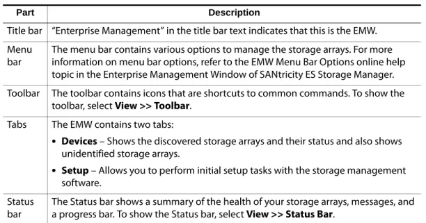
Table viewPart Description
Title bar “Enterprise Management” in the title bar text indicates that this is the EMW. Menu
bar
The menu bar contains various options to manage the storage arrays. For more information on menu bar options, refer to the EMW Menu Bar Options online help topic in the Enterprise Management Window of SANtricity ES Storage Manager. Toolbar The toolbar contains icons that are shortcuts to common commands. To show the
toolbar, select View >> Toolbar. Tabs The EMW contains two tabs:
•
Devices – Shows the discovered storage arrays and their status and also shows unidentified storage arrays.•
Setup – Allows you to perform initial setup tasks with the storage management software.Status bar
The Status bar shows a summary of the health of your storage arrays, messages, and a progress bar. To show the Status bar, select View >> Status Bar.
. . . Enterprise Management Window
SANtricity ES Storage Manager Concepts Guide for Version 10.70 2-3
Tree View
The Tree view provides a tree-structured view of the nodes in the storage system. The Tree view shows two types of nodes:
•
Discovered Storage Arrays•
Unidentified Storage ArraysBoth the Discovered Storage Arrays node and the Unidentified Storage Arrays node are child nodes of the storage management station node.
The Discovered Storage Arrays node has child nodes that represent the storage arrays that are currently managed by the storage management station. Each storage array is labeled with its machine name and is always present in the Tree view. When storage arrays and hosts with attached storage arrays are added to the EMW, the storage arrays become child nodes of the Discovered Storage Arrays node.
NOTE If you move the mouse over the storage management station node, a tooltip shows the controller’s IP address.
The Unidentified Storage Arrays node shows storage arrays that the storage management station cannot access because the name or IP address does not exist. You can perform these actions on the nodes in the Tree view:
•
Double-click the storage management station node and the Discovered Storage Arrays node to expand or collapse the view of the child nodes.•
Double-click a storage array node to launch the Array Management Window for that storage array.•
Right-click a node to open a pop-up menu that contains the applicable actions for that node.The right-click menu for the Discovered Storage Arrays node contains these options:
•
Add Storage Array•
Automatic Discovery•
RefreshThese options are the same as the options in the Tools menu. For more information, refer to the Using the Enterprise Management Window online help topic.
Introducing the Storage Management Software . . . .
Table View
Each managed storage array is represented by a single row in the Table view. The columns in the Table view show data about the managed storage array.
Sort the rows in the Table view in ascending order or descending order by either clicking a column heading or by selecting one of these commands:
•
View >> By Name•
View >> By Status•
View >> By Management Connection•
View >> By CommentShowing Managed Storage Arrays in the Table View
You can change the way that managed storage arrays appear in the Table view.
•
Select the storage management station node to show all of the known managed storage arrays in the Table view.•
Select a Discovered Storage Array node or Undiscovered Storage Array node in the Tree view to show any storage arrays that are attached to that specific host in the Table view.NOTE If you have not added any storage arrays, the Table view is empty.
Column Description
Name The name of the managed storage array. If the managed storage array is unnamed, the default name is Unnamed.
Type The type of managed storage array. This type is represented by an icon. Status An icon and a text label that report the status of the managed storage array. Management
Connections
Out-of-Band – This storage array is an out-of-band storage array. In-Band – This storage array is an in-band storage array that is managed through a single host.
Out-of-Band, In-Band – This storage array is a storage array that is both out-of-band and in-band.
Click Details to see more information about any of these connections. Comment Any comments that you have entered about the specific managed storage
. . . Array Management Window
SANtricity ES Storage Manager Concepts Guide for Version 10.70 2-5
•
Select a storage array node in the Tree view to show only that storage array in the Table view.NOTE Selecting an Unidentified node in the Tree view shows an empty Table view.
EMW Setup Tab
The EMW Setup tab is a gateway to tasks that you can perform when you set up a storage array. Using the EMW Setup tab, you can perform these tasks:
•
Add a storage array•
Name or rename a storage array•
Configure an alert•
Manage a storage array by launching the AMW•
Upgrade the controller firmware•
Open the Inherit Systems Settings windowArray Management Window
The Array Management Window (AMW) is JavaTM technology-based software that is launched from the Enterprise Management Window (EMW). The AMW provides management functions for a single storage array. You can have more than one AMW open at the same time to manage different storage arrays. The AMW includes these management functions for a storage array:
•
Provides storage array options, such as locating a storage array, configuring a storage array, renaming a storage array, or changing a password.•
Provides the ability to configure volumes from your storage array capacity, define hosts and host groups, and grant host or host group access to sets of volumes called storage partitions.•
Monitors the health of storage array components and reports a detailed status using applicable icons.•
Provides you with the applicable recovery procedures for a failed logical component or a failed hardware component.•
Presents a view of the Event Log for the storage array.•
Presents profile information about hardware components, such as controllers and drives.Introducing the Storage Management Software . . . .
•
Provides controller management options, such as changing ownership of volumes or placing a controller online or offline.•
Provides drive management options, such as assigning hot spares and locating the drive.•
Monitors storage array performance.Starting the Array Management Window
To start the Array Management Window (AMW) from the Enterprise Management Window (EMW), perform one of these tasks:
•
Click the Devices tab, and double-click the name of the storage array that you want to manage.•
Click the Devices tab, right-click the name of the storage array you want to manage, and select Manage Storage Array.•
Click the Devices tab, and select Tools >> Manage Storage Array.•
Click the Setup tab, and select Manage a Storage Array. In the Select Storage Array dialog, select the name of the storage array that you want to manage, and click OK.Parts of the Array Management Window
The Array Management Window (AMW) provides these areas for managing your storage array.
Title Bar
“Array Management” in the title bar indicates that this is the AMW.
Menu Bar
The menu bar contains various options to manage the storage array.
Toolbar
The toolbar contains icons that are shortcuts to common commands. To show the toolbar, select View >> Toolbar.
Storage Array Name
. . . Array Management Window
SANtricity ES Storage Manager Concepts Guide for Version 10.70 2-7
Tabs
The Array Management Window has these tabs:
•
Summary – Shows the status of the storage array. Information about the hardware components, capacity, hosts, mappings and storage partitions, volume groups, and volumes in the storage array appears. Additionally, the link to the Recovery Guru dialog appears when the storage array needs attention. Links to the Storage Array Profile dialog, relevant online help topics, and the storage concepts tutorial also appear in the Summary tab.•
Logical – Shows the organization of the storage array by volumes, volume groups, free capacity nodes, and any unconfigured capacity for the storage array. This tab is divided into two panes: the Logical pane on the left and the Properties pane on the right. The Logical pane provides a view of the logical components in the storage array in a tree structure. The Properties pane displays detailed information about the component that is selected in the Logical pane.•
Physical – Shows the organization of the storage array by controllers, drives, and other hardware components. This tab is divided into two panes: the Physical pane on the left and the Properties pane on the right. The Physical pane shows a graphical representation of the physical components in the storage array, such as the controller trays and the drive trays. The Properties pane displays detailed information about the component that is selected in the Physical pane.•
Mappings – Contains the Topology pane and the Defined Mappings pane. In the Topology pane, you can define the hosts, host groups, and host ports. TheTopology pane shows a tree-structured view of the logical nodes related to storage partitions in the storage array. The Defined Mappings pane shows the mapping that is associated with a selected logical node in the Topology pane. You can also change the mappings to grant volume access to host groups and hosts and create storage partitions.
•
Setup – Contains links to tasks that you can perform when setting up a storage array, such as configuring the storage array, setting the storage array password, and other tasks. Additionally, the links to configure the Ethernet management ports in the storage array, view and enable the premium features, and configure the iSCSI settings are shown in the Setup tab. You can click a link to open the corresponding dialog.•
Support – Contains links to tasks, such as recovering from a storage array failure; gathering support information, such as the Event Log and a description of a storage array; and sending the information to your Customer and Technical Support representative. The Support tab also contains the link to download the controller firmware, the NVSRAM, the drive firmware, the ESM firmware, and the ESM configuration settings. Additionally, the Support tab has links to view the description of all components and properties of a storage array, the Event Log of a storage array, online help, and the version and copyright information of the storage management software. You can click a link to open the corresponding dialog.Introducing the Storage Management Software . . . .
Status Bar
The status bar shows icons for the premium features that are available on your storage array. To show the status bar, select View >> Status Bar.
Summary Tab
The Summary tab in the Array Management Window (AMW) shows information about the storage array. Links to the Storage Array Profile dialog, relevant online help topics, and the storage concepts tutorial also appear. Additionally, the link to the Recovery Guru dialog appears when the storage array needs attention.
In the Summary tab, you can view this information:
•
The status of the storage array•
The hardware components in the storage array•
The capacity of the storage array•
The hosts, the mappings, and the storage partitions in the storage array•
The volume groups and volumes in the storage arrayLogical Tab
The Logical tab in the Array Management Window (AMW) contains two panes: the Logical pane and the Properties pane.
NOTE You can resize either pane by dragging the splitter bar, located between the two panes, to the right or to the left.
Logical Pane
The Logical pane provides a tree-structured view of the logical nodes. Click the plus (+) sign or the minus (-) sign adjacent to a node to expand or collapse the view. You can right-click a node to open a pop-up menu that contains the applicable actions for that node.
. . . Array Management Window
SANtricity ES Storage Manager Concepts Guide for Version 10.70 2-9
Nodes in the Logical Pane
The storage array, or root node, has three types of child nodes.
•
Volume – This node represents a configured and defined volume. Multiple Volume nodes can exist under a Volume Group node.•
Free Capacity – This node represents a region of capacity that you can use to create one or more new volumes within the volume group. Multiple Free Capacity nodes can exist under a Volume Group node.NOTE Multiple Unconfigured Capacity nodes appear if your storage array contains drives with different media types (hard drive or Solid State Disk [SSD]) and different interface types. Each drive type has an associated Unconfigured Capacity node shown under the Total Unconfigured Capacity node if unassigned drives are available in the drive tray.
Types of Volumes
These types of volumes appear under the Volume Group node:
•
Standard volumes.•
Primary volumes that participate in a mirror relationship in the primary role. Primary volumes are standard volumes with a synchronized mirror relationship. The remote secondary volume that is associated with the primary volume appears as a child node.•
Secondary volumes appear directly under the Volume Group node when the local storage array contains this volume.•
Mirror repository volumes.•
Snapshot repository volumes.•
Snapshot volumes are child nodes of their associated base volume.Child Nodes of the
Root Node Description of the Child Nodes
Unconfigured Capacity This node represents the storage array capacity that is not configured into a volume group.
Introducing the Storage Management Software . . . .
•
Source volumes are standard volumes that participate in a volume copy relationship. Source volumes are used as the copy source for a target volume. Source volumes accept host I/O requests and store application data. A source volume can be a standard volume, a snapshot volume, a snapshot base volume, or a Remote Volume Mirroring primary volume.•
Target volumes are standard volumes that participate in a volume copy relationship and contain a copy of the data from the source volume. Target volumes are read-only and do not accept write requests. A target volume can be created from a standard volume, the base volume of a snapshot volume, or a Remote Volume Mirror primary volume. The volume copy overwrites any existing volume data if an existing volume is used as a target.Properties Pane
The Properties pane provides detailed information about the component selected in the Logical pane. The information varies depending on what type of component is selected.
You can view the physical components that are associated with a logical component by selecting the Logical tab, right-clicking a component, and selecting View Associated Physical Components.
Physical Tab
The Physical tab in the Array Management Window contains two panes: the Physical pane and the Properties pane.
NOTE You can resize either pane by dragging the splitter bar, located between the two panes, to the right or to the left.
The Physical pane provides a view of the hardware components in a storage array, including their status. You can right-click a hardware component to open a pop-up menu that contains the applicable actions for that component.
NOTE The orientation of the Physical pane is determined by the actual layout of the storage array. For example, if the storage array has horizontal drive trays, the storage management software shows horizontal drive trays in the
Physical pane.
The Properties pane provides information for the hardware component that is selected in the Physical pane. The information in the Properties pane is specific to each
hardware component. If you select a controller icon in the Physical pane, a list of properties for that controller is shown in the Properties pane. If you select drive icon in the Physical pane, a list of properties for that drive is shown in the Properties pane.
. . . Array Management Window
SANtricity ES Storage Manager Concepts Guide for Version 10.70 2-11
Controller Status
The status of each controller is indicated by an icon in the Physical pane. This table describes the various controller icons.
View Tray Components
The View Tray Components command on each tray shows the status of the secondary components within the tray, such as power supplies, fans, and temperature sensors.
Icon Status
Online, Optimal
Offline
Service Mode
Slot Empty
Needs Attention (if applicable for your hardware model)
Suspended (if applicable for your hardware model)
Introducing the Storage Management Software . . . .
Drive Trays
For each drive tray that is attached to the storage array, a drive tray appears in the Physical pane. If your storage array contains different media types or different interface types, a drive type icon appears to indicate the type of drives in the drive tray. This table describes the different drive type icons that might appear.
This table describes the different drive interface type icons that might appear.
Show Drives List
The Show Drives list shows the valid drive configurations for the available trays. You can select a drive type from the list and click Show to indicate where the selected drive type is located in the tray. Click Hide to turn off the indicators.
Mappings Tab
The Mappings tab in the Array Management Window (AMW) contains two panes: the Topology pane and the Defined Mappings pane.
NOTE You can resize either pane by dragging the splitter bar, located between the two panes, to the right or to the left.
Icon Status
This drive tray contains only hard drives.
This drive tray contains only Solid State Disks (SSDs).
Icon Status
This drive tray contains only full disk encryption (FDE) security capable drives.
. . . Array Management Window
SANtricity ES Storage Manager Concepts Guide for Version 10.70 2-13
Topology Pane
The Topology pane shows a tree-structured view of logical nodes that are related to storage partitions. Click the plus (+) sign or the minus (-) sign adjacent to a node to expand or collapse the view. You can right-click a node to open a pop-up menu that contains the applicable actions for that node.
Nodes in the Topology Pane
The storage array, or the root node, has these types of child nodes.
NOTE If SANshare Storage Partitioning is disabled, all of the created volumes are in the Default Group.
•
Host Group – Defined host groups that are not participating in specific mappings are listed. This node can have host child nodes, which can have child host port nodes.•
Host – Defined hosts that are not part of a specific host group but are part of the Default Group and are not participating in specific mappings are listed. This node can have child host port nodes.NOTE The host nodes that are child nodes of this host group can also participate in mappings specific to the individual host rather than the host group.
Child Nodes of the
Root Node Description of the Child Nodes Undefined Mappings The Undefined Mapping node has one type of child node.
Individual Undefined Mapping – Represents a volume with an undefined mapping. Multiple Volume nodes can exist under an Undefined Mappings node.
Default Group
A Default Group node has two types of child nodes:
Unassociated Host Port Identifier
An Unassociated Host Port Identifier node has one type of child node. Host Port Identifier – Host port identifier that has not been associated with any host.
Host Group A Host Group node has one type of child node.
Host – Defined hosts that belong to this defined host group are listed. This node can have child host port nodes.
Host A Host node has one type of child node.
Host Port – This node has child nodes that represent all of the host ports or single ports on a host adapter that are associated with this host.
Introducing the Storage Management Software . . . .
Storage Partition Icon
The Storage Partition icon, when present in the Topology pane, indicates that a storage partition has been defined for the Default Group, a host group, or a host. This icon also appears in the status bar when storage partitions have been defined.
Defined Mappings Pane
The Defined Mappings pane shows the mappings associated with a node selected in the Topology pane.
The information in the table appears for a selected node.
NOTE An access volume mapping is not required for a storage array with an in-band connection and can be removed.
You can right-click a volume name in the Defined Mappings pane to open a pop-up menu. The pop-up menu contains options to change and remove the mappings. The information shown in the Defined Mappings pane varies according to what node you select in the Topology pane, as shown in this table.
Column Name Description
Volume Name The user-supplied volume name.
The factory-configured access volume also appears in this column.
Accessible By Shows the Default Group, a defined host group, or a defined host that has been granted access to the volume in the mapping.
LUN The LUN assigned to the specific volume that the host or hosts use to access the volume.
Volume Capacity Shows the volume capacity in units of GB.
Type Indicates whether the volume is a standard volume or a snapshot volume.
Node Selected Information That Appears in the Defined Mappings Pane Root (storage array) node All defined mappings.
Default Group node or any child node of the Default Group
All mappings that are currently defined for the Default Group (if any).
Host Group node (outside of Default Group)
. . . Array Management Window
SANtricity ES Storage Manager Concepts Guide for Version 10.70 2-15
AMW Setup Tab
The AMW Setup tab provides links to these tasks:
•
Locating the storage array•
Renaming the storage array•
Setting a storage array password•
Configuring the storage array•
Defining the hosts and host ports•
Mapping volumes to hosts•
Saving configuration parameters in a file•
Configuring the Ethernet management ports•
Viewing and enabling the premium featuresSupport Tab
The Support tab in the AMW provides links to these tasks:
•
Recovering from a storage array failure by using the Recovery Guru•
Gathering support information, such as the Event Log and a description of the storage array, to send to your Customer and Technical Support representative•
Viewing the description of all components and properties of the storage array•
Downloading the controller firmware, the NVSRAM, the drive firmware, the ESM firmware, and the ESM configuration settings•
Viewing the Event Log of the storage array•
Viewing the online help topics•
Viewing the version and copyright information of the storage management softwareYou can click a link to open the corresponding dialog.
Host node that is a child node of a Host Group node
All mappings that are currently defined for the Host Group, plus any mappings specifically defined for a specific host. Host Port node or individual host port
node outside of the Default Group
All mappings that are currently defined for the host port’s associated host.
Introducing the Storage Management Software . . . .
Managing Multiple Software Versions
When you open the Array Management Window (AMW) to manage a storage array, the version of software that is appropriate for the version of firmware that the storage array uses is opened. For example, you manage two storage arrays using this software; one storage array has firmware version 6.14, and the other has firmware version 7.7x, where
x represents a number. When you open the AMW for a particular storage array, the correct AMW version is used. The storage array with firmware version 6.14 uses
version 9.14 of the storage management software, and the storage array with firmware version 7.7x uses version 10.1x of the storage management software. You can verify the version that you are currently using by selecting Help >> About in the AMW.
This bundling of previous versions of the AMW provides the flexibility of upgrading the firmware only on selected storage arrays instead of having to perform an upgrade on all of the storage arrays at one time.
SANtricity ES Storage Manager Concepts Guide for Version 10.70 3-1
Chapter
3
Configuring the Storage Arrays
Volumes and Volume Groups
When you configure a storage array for the first time, you must consider which data protection strategy is most appropriate for your storage array, together with how the total storage capacity must be organized into volumes and shared among hosts. The storage management software identifies several distinct volumes:
•
Standard volumes•
Snapshot volumes•
Snapshot repository volumes•
Primary volumes•
Secondary volumes•
Mirror repository volumes•
Source volumes•
Target volumesStandard Volumes
A standard volume is a logical structure that is created on a storage array for data storage. A standard volume is defined from a set of drives called a volume group, which has a defined RAID level and capacity. You can create a volume from unconfigured capacity, unassigned drives, or Free Capacity nodes on the storage array. If you have not configured any volumes on the storage array, the only node that is available is the Unconfigured Capacity node.
Use the Create Volume Wizard to create one or more volumes on the storage array. During the volume creation process, the wizard prompts you to select the capacity to allocate for the volumes and to define basic volume parameters and optional advanced volume parameters for the volume.