3rd and 4th RF
Channel Packages
Installation
• Overview, this page
• Safety Precautions, this page • Requirements, page 2 • Parts List, page 2
• Installation Procedure, page 2
• Powering Up, Configuring, and Testing, page 7 • RF Channel Interchange Module, page 9 • Schematic Drawings, page 9
Overview
Varian’s 3rd and 4th rf channel packages add new, independent rf transmitter channels to
UNITYINOVA or UNITYplus NMR spectrometer systems. The packages differ depending on
the proton frequency of the spectrometer, whether the channels are broadband or fullband, and whether the package is for 3rd channel only or for both 3rd and 4th channels. Packages covered in this manual include Part Nos. 993450-00, 993451-00, 993452-00, 00-993453-00, 00-993455-00, 00-993457-00, 00-993459-00, 00-993462-00, 00-993463-00, 00-993465-00, and 00-993465-04. This manual also covers installation of the RF Channel Interchange Module, Part Nos. 01-904799-XX.
Safety Precautions
CAUTION:
Only qualified maintenance personnel shall remove equipment covers or make internal adjustments. The system contains delicate components that can be easily damaged. Before workingthe back of the console. Take electrostatic discharge (ESD) precautions to avoid damage to sensitive electronic components.
Requirements
UNITYINOVA or UNITYplus NMR spectrometer system.
Parts List
The following parts are required to install the packages:
• AMT amplifier kit, which, depending on the channel configuration specified on the order, includes:
•AMT amplifier
•Cables, relays, attenuators, and hardware • PTS frequency synthesizer kit, which includes:
•PTS frequency synthesizer
•Connector board
•Power cord, coax cables, and hardware
• Nth Channel kit (Part No. 00-992951-00), which includes:
•Transmitter and Controller boards
•Coax cables and hardware
•Attenuator board, 3rd channel or 4th channel
Installation Procedure
Installation involves preparing to install the hardware; installing the PTS frequency synthesizer, transmitter board, transmitter controller board, pulse amplifier, and switching relays (if applicable); and then configuring and testing the system.
For parts layout, wiring diagrams, and various optional configurations, refer to the system interconnect schematic drawing (Pub. No. 01-903010-00 forUNITYINOVA, or Pub. No.
87-195901-00 for UNITYplus).
Preparing to Install the Hardware
1. Stop the acquisition process in the host computer (in a shell window enter the commandsu acqproc, or becomerootand enterkillacqproc) and turn off the cabinet power supply. Remove the cabinet’s power cable from the connector at the rear of the power supply.
Installing the PTS Synthesizer
1. Remove the blank panel above the existing synthesizer. Remove the moving parts of two chassis slides from the cabinet position where the synthesizer is to be mounted. This is usually the position immediately above the existing synthesizers.
2. Attach the slide parts to the new synthesizer using four 8-32 screws and slide shims (00-993161-00).
3. Attach the PTS Connector board (00-992106-00) to the Remote Control input connector at the rear of synthesizer.
4. Set switches on the PTS Connector board:
• For channel 3, set positions 3 of SW1 and SW2 on and all other positions off. • For channel 4, set positions 4 of SW1 and SW2 on and all other positions off. 5. Connect the overrange cable (00-993015-00), if supplied, between P9 on the PTS
Connector board and the 9-pin D connector at the rear of the synthesizer.
6. Make sure the INT. STD/EXT. STD switch on the synthesizer is set to the EXT. STD position.
7. Mount the synthesizer in the cabinet. Install four cage nuts (23-101008-00) at appropriate places in the cabinet’s rack mounting rail so that the synthesizer can be secured with the four screws (23-101009-00) provided.
8. Connect a free Frequency Bus ribbon cable connector to the PTS Connector board at the rear of the new synthesizer.
9. Connect the supplied power cable between the synthesizer's input connector and the cabinet’s power strip (at center rear of the cabinet).
10. Connect the short coaxial cable (00-958297-0x) between the synthesizer’s 5/10MHz IN connector and an unused connector at the signal splitter assembly located at the upper rear of the cabinet, behind the synthesizers.
11. Connect a long coaxial cable (00-958298-11) to the synthesizer’s MAIN OUTPUT connector. Route this cable through the cable tray below the rf cardcage (upper cardcage), through the hole below the cardcage, and to the front of the cardcage. This will connect to J2X4 on the Transmitter board that will be installed later.
Installing Transmitter and Transmitter Controller Boards
Refer toFigure 1,Figure 2, andFigure 3 for cable diagram an slot assignments forUNITYINOVA and UNITYplus rf control cardcage and rf cardcage.
1. Remove blank panels as necessary from the two cardcages.
Refer toFigure 1for rf control cardcage front view and toFigure 2andFigure 3for rf cardcage rear and front views, respectively.
Transmitter 3 and Transmitter Controller 3 go into slot 7 of the rf cardcage and slot 15 of the rf control cardcage, respectively. Transmitter 4 and Transmitter Controller 4 go into slot 6 of the rf cardcage and slot 13 of the rf control cardcage, respectively. Cardcage slots are numbered from the left as viewed from the front.
2. Connect, at the rear of the rf cardcage, a thin yellow coaxial cable (00-993198-03) that will carry the reference frequency from the Reference Generator board
(00-Figure 1. RF Control Cardcage, Front View, Showing Slot Assignments
AP & F
HS & R Lock Transceiver Controller Receiver Controller & Clock Generator Transmitter Controller 4 WFG 2 (optional) Magnet leg & Interface
Slot 1 Slot 3 Slot 7 Slot 11 Slot 12 Slot 13 Slot 14 Slot 15 Slot 16 Slot 17 Slot 18 Slot 19 Slot 20 Slot 21
WFG 4 (optional) WFG 3 (optional) Transmitter Controller 3 Transmitter Controller 2 WFG 1 (optional) Transmitter Controller 1 Amp & Route
J200
2/3/4-Channel Attenuator & Switch
J212 J222 J232 J242 J252 J262 J272 J282 J292 J291 J281 J271 J261 J251 J241 J231 J221 J211
Transmitter 1 Transmitter 2 Transmitter 3 Transmitter 4
Receiver SPARE Lock Transceiver Reference Generator C A C A C A C A C A C A C A C A C A CX1 Power & Ground 10MHz 42MHz
Slot Slot Slot Slot Slot Slot Slot Slot Slot
10 9 8 7 6 5 4 3 2 To Transmitter Controller 1 To Transmitter Controller 2 To Transmitter Controller 3 To Transmitter Controller 4 To Receiver Controller To Lock Transceiver Controller To
Amp & Route
J202 J201 Slot
1
SPARE
The coaxial connector snaps into its receptacle but requires a special tool to remove it. Be sure to install the connectors in the proper sockets. Refer toFigure 2showing the rear view of the rf cardcage.
3. Clip the cable tie and install the one supplied around all cables. 4. Replace the boards that were removed instep 1.
5. Install the new Transmitter board and Transmitter Controller board in their respective slots.
6. Reinstall the blank panels in any remaining empty cardcage slots.
CAUTION:
The cardcage could overheat if the blank panels are not reinstalled into the empty cardcage slots.7. Set the selector switch on the front of the new Transmitter Controller board to position 3 for rf channel 3 or 4 for rf channel 4.
8. Connect a small coaxial cable (00-992897-04, 15 inches long) between one of the empty receptacles at the front of the Receiver Controller & Clock Generator board and J3X1 at the front of the new Transmitter Controller board.
9. Connect the synthesizer output cable (step 11 onpage 3 in“Installing the PTS Synthesizer”) to J2X4 of the newly installed transmitter.
10. Remove the input and output coaxial cables from the front panel of the Attenuator board in the RF Cardcage. Install the new Attenuator board in the same slot of the RF Cardcage. Replace the input and output cables you just removed.
11. Connect the short coaxial cable (00-958298-03) between J2X3 of the newly installed transmitter and the channel 3 or channel 4 input connector at the Attenuator board. 12. Connect a long coaxial cable (00-958297-10, 5 feet long) to the appropriate channel
Reference Generator Lock Transceiver Spare Receiver Transmitter 4
Slot 1 Spare Slot 2 Slot 3 Slot 4 Slot 5 Slot 6 Slot 7 Slot 8 Slot 9 Slot 10
Transmitter 3 Transmitter 2 Transmitter 1 2 / 3 / 4 Channel Attenuator Switch
Figure 4. Third and Fourth Channel Cable Routing Diagrams L 3rd Channel B ATTN/SW OUT 4 H 3rd Channel L o o OUT 3 OUT 4 B A ATTN/SW L 3rd Channel 4th Channel OUT 4 B ATTN/SW L 3rd Channel 4th Channel L OUT 3 OUT 4 A B ATTN/SW H 3rd Channel 4th Channel L o OUT 3 OUT 4 A B ATTN/SW 3rd Channel 4th Channel OUT 3 OUT 4 ATTN/SW H L L H A B o o A B o o amptype='aal' amptype='aaa' amptype='aaln' amptype='aall' amptype='aaan' amptype='aaaa' Ifdfrq2=dfrq3, both signals are routed through OUT 3.
Installing Pulse Amplifier and Switching Relays
If applicable, the new Pulse Amplifier (AMT) mounts in the cabinet below the existing amplifier. Refer toFigure 1,Figure 2, andFigure 3for cable diagram and slot assignments
forUNITYINOVA and UNITYplus rf control cardcage and rf cardcage.
1. Remove the appropriate screws to remove the blank front panel and two moveable slide parts from the cabinet. Mount the slides on the new amplifier and install it in the cabinet.
2. Connect the ribbon cable (00-993025-11) between J2A2 on the front panel of the Amp & Route board in the rf control cardcage and the D connector at the rear of the AMT. Route the cable under the card cage and through the cable tray at the rear of the cardcage.
3. Assemble the AMT rear panel and vent duct using 6-32 hardware. Remove the blank panel and install the vent and duct assembly at the rear of the cabinet, above the existing panel assembly.
This duct will guide the amplifier’s cooling air exhaust out of the cabinet.
4. Connect coaxial cables between the outputs of the Attenuator board and the channel inputs of the AMT. Locate the configuration inFigure 4 that matches the
configuration being installed and connect the coax cables as shown.
5. Connect the heavy coaxial cables with the type N connectors to the channel outputs of the AMT.
Route these cables through the holes in the vent panel to the magnet/console interface cabinet. They will be connected to bandpass filters or relays instep 8below. 6. Connect the supplied power cable between the amplifier’s power input connector
and the cabinet’s power strip (at center rear of the cabinet).
7. Secure the amplifier’s front panel to the cabinet rails using the screws removed in step 1 above.
8. If the channel being installed is a “dual full band” channel, install relays K1003 or K1004 in the electronics cabinet (near K1001, behind the rf control cardcage) and connect them to the Relay Driver board, and to the Attenuator board and AMT amplifier.
9. Install relay K5009 or K5010 (if present) in the magnet/console interface cabinet and connect them to the Magnet Leg Driver board and to the cables from the AMT amplifier and to the probe/filter cables.
Powering Up, Configuring, and Testing
1. Set the power switch on the AMT to on. Reconnect the main power cable and turn on the system power.
2. Press the reset button on the Acquisition CPU board to reboot the acquisition hardware.
3. In a shell window, entersu acqproc to restart the acquisition process.
The computer interrogates the newly installed hardware to determine its configuration.
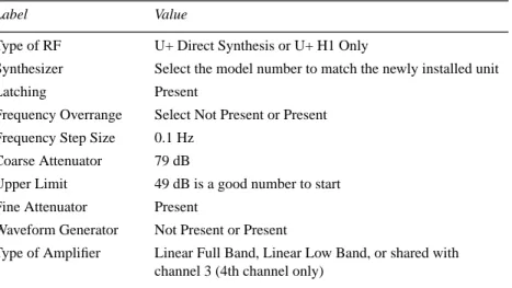
5. Pull down the channel Configure: menu and select the channel to be configured— RF Channel 2 (Dec), RF Channel 3 (Dec2), or RF Channel 4 (Dec3). Verify or set the parameters listed inTable 1.
6. Repeatstep 5 for the next channel if installed.
7. Select the Exit and Save button in the top panel to enter the values.
8. Test the new rf channel for functionality. Note that none of the experiments will have appropriate parameters for the third and/or fourth channel until a parameter set is retrieved into that experiment with thert orrtp command.
9. Recall a parameter set:
rt('/vnmr/stdpar/H1') dn2='C13' su
Verify that the output of the installed PTS is 10 dBm.
10. Entercreate('dpwrf2') setlimit('dpwrf2',4095,0,1). Note that if the Waveform Generator board is not installed in the channel being tested, use the parameterdpwrm instead ofdpwrf.
11. Connect the output of the transmitter to a scope and enter:
dpwrf2=255,511,1023,2047,4095 d1=5 dm2='y' go
12. Verify that the output voltage changes by 6 dB. Whendpwrf2=4095, the output should be about 10 dBm.
13. Setdpwrf2=4095 dm2='n' and entersu.
14. Connect the output (seeFigure 4) of the ATTN/SW to a scope. 15. Setdm='n' dm2='y' (if presentdm3='n')nt=1 d1=5
dpwr2=10,20,30,40 (not higher!) and entergo. Verify that the amplitude increases by 10 dB each time.
16. If the fourth channel is present, repeat steps 10 through 15 to check it.
Table 1. CONFIG Labels and Values for 3rd or 4th RF Channel
Label Value
Type of RF U+ Direct Synthesis or U+ H1 Only
Synthesizer Select the model number to match the newly installed unit
Latching Present
Frequency Overrange Select Not Present or Present
Frequency Step Size 0.1 Hz
Coarse Attenuator 79 dB
Upper Limit 49 dB is a good number to start
Fine Attenuator Present
Waveform Generator Not Present or Present
Type of Amplifier Linear Full Band, Linear Low Band, or shared with channel 3 (4th channel only)
RF Channel Interchange Module
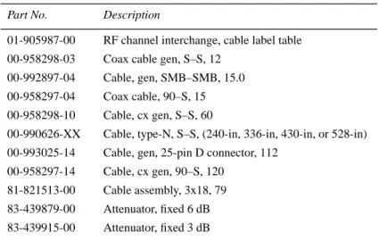
The RF Channel Interchange Module (Part Nos. 01-904799-XX, where XX varies according to whether the cable length is 16, 24, 32, or 40 feet) provides the cables required for a third or fourth rf channel. With these cables installed, it is easier to share the hardware components for a third or fourth rf channel between twoUNITYINOVA NMR spectrometers.
To install the cables, refer to the system interconnect drawing, cable label table, and, if necessary, the procedures in this manual.Table 2 lists the parts in a module.
Schematic Drawings
Refer to the system schematics published for the NMR spectrometer system.
Table 2. Parts List, RF Channel Interchange Module
Part No. Description
01-905987-00 RF channel interchange, cable label table 00-958298-03 Coax cable gen, S–S, 12
00-992897-04 Cable, gen, SMB–SMB, 15.0
00-958297-04 Coax cable, 90–S, 15 00-958298-10 Cable, cx gen, S–S, 60
00-990626-XX Cable, type-N, S–S, (240-in, 336-in, 430-in, or 528-in) 00-993025-14 Cable, gen, 25-pin D connector, 112
00-958297-14 Cable, cx gen, 90–S, 120 81-821513-00 Cable assembly, 3x18, 79 83-439879-00 Attenuator, fixed 6 dB 83-439915-00 Attenuator, fixed 3 dB
3rd and 4th RF Channel Packages Installation
UNITYINOVA and UNITYplus NMR Spectrometer Systems
Pub. No. 01-999135-00, Rev. B0599
Technical contributors: Tim Luca, Mark Van Criekinge, Frits Vosman, Phil Hornung Technical writer: Dan Steele
Technical editor: James Welch Revision history:
A0399 – Initial release
B0599 – Added RF Channel Interchange Module Copyright © 1999, Varian, Inc.
3120 Hansen Way, Palo Alto, California 94304 http://www.varianinc.com
All rights reserved. Printed in the United States
The information in this document has been carefully checked and is believed to be entirely reliable. However, no responsibility is assumed for inaccuracies. Statements in this document are not intended to create any warranty, expressed or implied. Specifications and performance characteristics of the software described in this manual may be changed at any time without notice. Varian reserves the right to make changes in any products herein to improve reliability, function, or design. Varian does not assume any liability arising out of the application or use of any product or circuit described herein; neither does it convey any license under its patent rights nor the rights of others. Inclusion in this document does not imply that any particular feature is standard on the instrument.
UNITYINOVA, UNITYplus, UNITY, Gemini, GuidePath, VXR, XL, VNMR, VnmrS, VnmrX, VnmrI,
VnmrV, VnmrSGI, MAGICAL, AutoLock, AutoShim, AutoPhase, limNET, and SMS are registered trademarks or trademarks of Varian, Inc.
UNIX is a registered trademark of The Open Group.
Sun, SunOS, Suninstall, SPARC, SPARCstation, Ultra, Sun-4, SunCD, SunView, and NFS are registered trademarks or trademarks of Sun Microsystems, Inc. and SPARC International. VxWorks and VxWorks Powered are registered trademarks of WindRiver Systems, Inc. Oxford is a registered trademark of Oxford Instruments LTD.
Ethernet is a registered trademark of Xerox Corporation.