Prof.Dr.H.Ziegler
Dedicated Application Layer (M-Bus)
Foreword
This document has been prepared by the WG4 of CEN TC 294.This document is a working document.
Scope:
This standard is a backward compatible enhancement to EN1434-3 and is interoperable with EN13757.
1. Introduction
The bus communication system of EN1434-3 is commonly called M-Bus. Its application layer describes
a standard especially for meter readout. It can be used with various physical layers and with link layers
and network layers which support the transmission of variable length binary transparent telegrams.
The first byte of an application layer telegram is the CI-field (Control Information) which distinguishes
between various telegram types and application functions. It is also used to distinguish between true
application layer communication and management commands for lower layers. The meaning of the
remaining bytes of the telegram depends also on the value of the CI-field. This second revision is a
compatible enhancement of the sections 6.4 to 6.6 of the original standard EN1434-part 3:1997.
Besides some clarifications and implementation hints it contains optional enhancements especially for
complex meters. Due to technical progress some variants (Fixed format and mode 2=high byte first)
are no longer supported in this standard.
Note that this standard contains only directions how data should be coded. It is beyond the task of an
application layer standard to define which data must be transmitted under what conditions by which
types of slaves or which data transmitted to a slave must have which reactions. Therefore adherence
to this standard guarantees the coexistence and common communication and readout capability of
slaves via a universal master software (covering all optional features), but not yet functional or
communication interchangeabilty of meters following this standard. For several meter types and meter
classes the company “Fernwärme Wien” and the “AGFW”-group of remote heating users have
provided such application descriptions required for full interchangeability. They are accessible via the
www-server of the m-bus users group (http://www.m-bus.com).
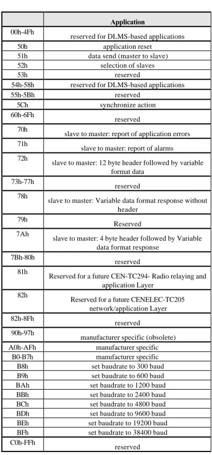
2. CI-Field
2.1 Overview
The original EN1434-3 defined two possible data sequences in multibyte records. This standard supports only the mode where the least significant byte of a multibyte record is transmitted first.
Application
00h-4Fh
reserved for DLMS-based applications
50h application reset
51h data send (master to slave)
52h selection of slaves
53h reserved
54h-58h reserved for DLMS-based applications
55h-5Bh reserved
5Ch synchronize action
60h-6Fh
reserved 70h
slave to master: report of application errors 71h
slave to master: report of alarms 72h
slave to master: 12 byte header followed by variable format data
73h-77h
reserved 78h
slave to master: Variable data format response without header
79h
Reserved 7Ah
slave to master: 4 byte header followed by Variable data format response
7Bh-80h
reserved 81h
Reserved for a future CEN-TC294- Radio relaying and application Layer
82h
Reserved for a future CENELEC-TC205 network/application Layer 82h-8Fh
reserved 90h-97h
manufacturer specific (obsolete)
A0h-AFh manufacturer specific
B0-B7h manufacturer specific
B8h set baudrate to 300 baud
B9h set baudrate to 600 baud
BAh set baudrate to 1200 baud
BBh set baudrate to 2400 baud
BCh set baudrate to 4800 baud
BDh set baudrate to 9600 baud
BEh set baudrate to 19200 baud
BFh set baudrate to 38400 baud
C0h-FFh
reserved
Note that the CI-codes 50h, 52h, 5Ch, 70h, 71h, 78h, 7Ah, 80h, 81h, A0h-AFh and B8h-BFh are optional compatible enhancements of the original standard. Note also that even if the functions of these optional CI-codes are not implemented in a slave the link layer protocol requires a proper link layer acknowledge of SND_UD telegrams containing any of these CI-codes.
2.2 Application reset (CI = 50h), (optional)
With the CI-Code 50h the master can release a reset of the application layer in the slaves. Each slave himself decides which parameters to change - e.g. which data output is default - after it has received such an application reset. This application reset by a SND_UD with CI=50h is the counterpart to the reset of the data link layer by a SND_NKE.
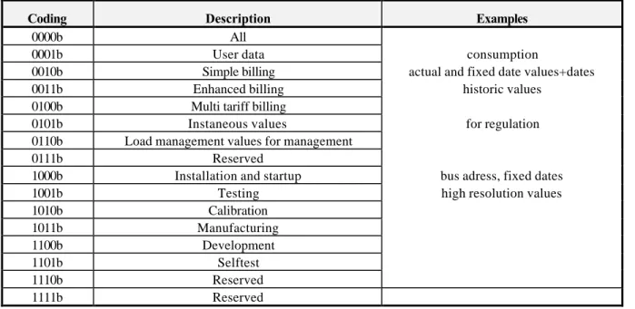
2.2.1 Application reset subcode (optional)
It is allowed to use optional parameters after CI = 50h. If more bytes follow, the first byte is the application reset subcode. Further bytes are ignored. The application reset subcode defines which telegram function and which subtelegram is requested by the master. The datatype of this parameter is 8 bit binary. The upper 4 bits define the telegram type or telegram application and the lower 4 bits define the number of the subtelegram. The lower four bits may me ignored for slaves which provide only a single telegram for each application. The use of the value zero for the number of the subtelegram means that all telegrams are requested.
Slaves with only one type of telegram may ignore application reset and the added parameters but have to confirm it (E5h).
The following codes can be used for the upper 4 bits of the first parameter:
Coding Description Examples
0000b All
0001b User data consumption
0010b Simple billing actual and fixed date values+dates
0011b Enhanced billing historic values
0100b Multi tariff billing
0101b Instaneous values for regulation
0110b Load management values for management
0111b Reserved
1000b Installation and startup bus adress, fixed dates
1001b Testing high resolution values
1010b Calibration 1011b Manufacturing 1100b Development 1101b Selftest 1110b Reserved 1111b Reserved
Note that this table has been expanded with optional elements from the original standard.
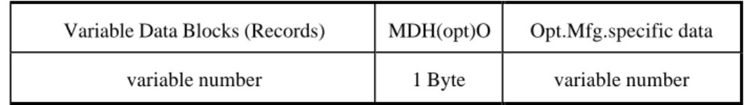
2.3 Master to slave data send (51h) (optional)
The CI-Field code 51h is used to indicate the data send from master to slave:
Variable Data Blocks (Records) MDH(opt)O Opt.Mfg.specific data
variable number 1 Byte variable number
Fig. 1 Variable Data Structure master to slave
Note that this structure is identical to the slave to master direction (see chapter 4) with the exception of the fixed header which is omitted in this direction.
2.4 Slave select (52h) (optional)
The CI-Field code 52h is used for the management of the optional secondary addressing (See chapter 9).
2.5 Synchronize action (CI = 5Ch) (optional)
This CI-code can be used for synchronizing functions in slaves and masters (e.g. clock synchronization). Special actions or parameter loads may be prepared but their final execution is delayed until the reception of such a special CI-field command.
2.6 Report of application errors (slave to master) (CI = 70h) (optional) For details of the report of application errors see chapter 6.
2.7 Report of alarm status (slave to master) (CI = 71h) (optional) For details of the report of alarm status errors see appendix C.
2.8 Variable data respond (slave to master) (CI = 72h, 78h, 7Ah) For details see chapter 3
2.9 Baudrate switch commands B8h-BFh (optional)
These optional commands can be used by a master to switch the baudrate of a slave. For details see chapter 9.1.
3
Variable data respond (CI=72h, CI=78h, CI=7Ah)
Data Header of variable data respond The CI-Field codes 72h, 78h, 7Ah are used to indicate the variable data structure in long frames (RSP_UD) with optional fixed header. Note that the CI-fields 78h and 7Ah are extensions from the EN1434-3. They are recommended for new master implementations to simplify the integration of radio based communication.
Figure 2 shows the way this data is represented.
Data Header(Req.) Variable Data Blocks (Records) MDH(opt)O Opt.Mfg.specific data Opt) 0 byte (CI=78h)
4 byte (CI=7Ah) 12 byte (CI=72h)
variable number 1 Byte variable number
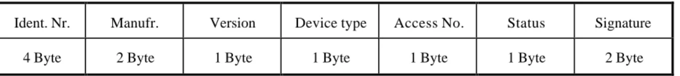
Fig. 2 Variable Data Structure in Answer Direction 3.1 Structure of Data Header (CI=72h)
The first twelve bytes of the user data consist of a block with a fixed length and structure (see fig. 3).
Ident. Nr. Manufr. Version Device type Access No. Status Signature
4 Byte 2 Byte 1 Byte 1 Byte 1 Byte 1 Byte 2 Byte
Fig. 3 Data Header CI=72h
3.2 Structure of Data Header (CI=7Ah)
The first four bytes of the user data consist of a block with a fixed length and structure (see fig. 4).
This CI-field is proposed for systems using the future physical and link layer standardfor radio communication. In this standard the link layer adress contains the information fields of the manufacturer, the device type, the version and the identification number, so that these 8 bytes from the fixed header of the CI=72h are not required in the application layer part of a telegram.
Access No. Status Signature
Fig. 4 Data Header CI=7Ah
3.3 Identification number
The Identification Number is either a fixed fabrication number or a number changeable by the customer, coded with 8 BCD packed digits (4 Byte), and which thus runs from 00000000 to 99999999. It can be preset at fabrication time with a unique number, but could be changeable afterwards, especially if in addition an unique and not changeable fabrication number (DIF = 0Ch, VIF = 78h, see chapter 6.7.3) is provided.
3.3 Manufacturer identification
The field manufacturer is coded unsigned binary with 2 bytes. This manufacturer ID is calculated from the ASCII code of EN 61107 manufacturer ID (three uppercase letters) with the following formula:
Man. ID = [ASCII(1st letter) - 64] • 32 • 32 + [ASCII(2nd letter) - 64] • 32 + [ASCII(3rd letter) - 64]
Note that currently the flag association administers these three letter manufacturers ID of EN61107.
3.4 Version identification
The field version specifies the generation or version of the meter and depends on the manufacturer. It can be used to make sure, that within each version number the identification # is unique.
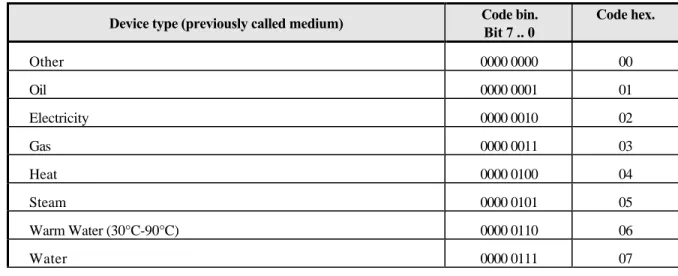
3.5 Device type identification
The devicebyte is coded as follows:
Device type (previously called medium) Code bin.Bit 7 .. 0 Code hex.
Other 0000 0000 00 Oil 0000 0001 01 Electricity 0000 0010 02 Gas 0000 0011 03 Heat 0000 0100 04 Steam 0000 0101 05 Warm Water (30°C-90°C) 0000 0110 06 Water 0000 0111 07
Heat Cost Allocator. 0000 1000 08
Compressed Air 0000 1001 09
Cooling load meter (Volume measured at return temperature: outlet)
0000 1010 0A
Cooling load meter (Volume measured at flow temperature: inlet) 0000 1011 0B
Heat (Volume measured at flow temperature: inlet) 0000 1100 0C
Heat / Cooling load meter 0000 1101 OD
Bus / System component 0000 1110 0E
Unknown Medium 0000 1111 0F
Reserved ... 10 to 14
Hot water (>=90°C) 0001 0101 15
Cold Water 0001 0110 16
Dual register (hot/cold) Water meter (See note 1) 0001 0111 17
Pressure 0001 1000 18
A/D Converter 0001 1001 19
Reserved ... 1Ah to
FFh
Table 3 Device type identification
Note 1: such a meter registers water flow above a limit temperature in a separate register with an appropriate tariff ID.
Note that this table has been expanded with optional elements from the original standard.
3.6 Access number
The Access Number has unsigned binary coding, and is incremented (modulo 256) by one before or after each RSP_UD from the slave. Since it can also be used to enable private end users to detect an unwanted overfrequently readout of its consumption meters, it should not be resettable by any bus communication.
3.7 Status byte
Bit Meaning with Bit set Significance with Bit not set
0,1 See table 5 See table 5
2 Power low Not power low
3 Permanent error No permanent error
4 Temporary error No temporary error
6 Specific to manufacturer Specific to manufacturer
7 Specific to manufacturer Specific to manufacturer
Table 4 Coding of the Status Field
Status bit 1 bit 0
Application status
0 0
No Error
0 1
Application Busy
1 0
Any Application Error
1 1
Reserved
Table 5 Application Errors coded with the Status-Field
Note that more detailed error signalling can be provided by application telegrams starting with CI=70h and/or using data records signalling even more detailed error information.
3.8 Signature field
The Signature is reserved for optional Encryption of the application data. Such an encryption might be required for transmit only wireless meter readout. It is assumed, that each meter (or a group of meters) could have an individual encryption key. If no Encryption is used its value shall be 00 00 h.
3.8.1 Functions
Data privacy for consumption meters values Detecting simulated meter transmission Preventing later playback of old meter values 3.8.2 Structure of encrypted telegrams
a) The first 12-byte block containing the ID-number, the manufacturer etc. is always unencrypted. The last word of this block is the signature word. If the following data are unencrypted, this signature word contains a zero.
b) If the transmission contains encrypted data, the high byte of this ture word contains a code for the encryption method. The code 0 signals
no encryption. Currently only the encryption codes 02xxh or 03xxh (see below) are defined. The other codes are reserved. The number of encrypted bytes is contained in the low byte of the signature word. The content of this signature word had been defined in the EN1434-3 as zero, corresponding consistently to no encrypted data.
c) The encrypted data follow directly after the signature word, thus forming the beginning of the DIF/VIF-structured part of the telegram.
a) If the number of encrypted bytes is less than the remaining data of the telegram, unencrypted data may follow after the encrypted data. They must start at a record boundary, i.e. the first byte after the encrypted data will be interpreted as a DIF.
b) If a partially encrypted telegram must contain encrypted manufacturer specific data a record with a suitable length DIF (possibly a variable length string DIF) and a VIF= 7Fh (manufacturer specific data record) must be used instead of the usual MDH-DIF=0Fh. This is required to enable after decryption standard DIF/VIF-decoding of a previously partially encrypted telegram containing
encrypted manufacturer specific data . 3.8.4 Encryption methods
a) Encryption according to the DES (data encryption standard) as described in ANSI X3.92-1981
b) Cipher Block Chaining (CBC)-method as described in ANSI X3.106-1983 with an initial initialization vector of zero: (Encryption Method Code=02xxh). In this case the data records should contain the current date before the meter reading.
Note that in this case the data after the date record, i.e.especially the encrypted meter reading data change once per day even if their data content itself is constant. This prevents an undetectable later playback of stored encrypted meter readings by a hacker.
c) The "Initialization Vector IV" with length 64 bits of this standard may alternatively be defined by the the first 6 bytes of the identification header in mode 1 sequence, i.e. identification number in in the lowest 4 bytes followed by the manufacturer ID in the two next higher bytes and finally by the current date coded as in record structure "G" for the two highest bytes.
In this case the Encryption method is coded as "03xxh". Note that in this case all encrypted data change once per day even if the data content itself is constant. This prevents an undetectable later playback of any stored encrypted data by a hacker.
d) To simplify the verification of correct decoding and to prevent an undetected change in the identification of the not encrypted header, the encrypted part of the telegram must contain at least together with the appropriate application layer coding (DIF and VIF) again the same identification number as in the unencrypted header.
e) Due to the mathematical nature of the DES-algorithm the encrypted length contained in the low byte of the signature word must be an integer multiple of 8 if the high byte signals DES-Encryption.
with appropriatly structured dummy data records to achieve the required record boundary at the end of the encrypted data. One or several bytes containing the filler DIF=2Fh are suggested to fill such gaps.
f) The application of certain Encryption methods might be prohibited by local laws.
4 Variable Data Blocks (Records)
The data, together with information regarding coding, length and the type of data is transmitted in data records in arbitrary sequence. As many records can be transferred as there is room for within the maximum total data length of 234 Bytes, and taking account of the C, A, and CI fields, and the data header. This limits the total telegram length to 255 bytes. This restriction is required to enable gateways to other link- and application layers. The manufacturer data header (MDH) is made up by the character 0Fh or 1Fh and indicates the beginning of the manufacturer specific part of the user data and should be omitted, if there are no manufacturer specific data.
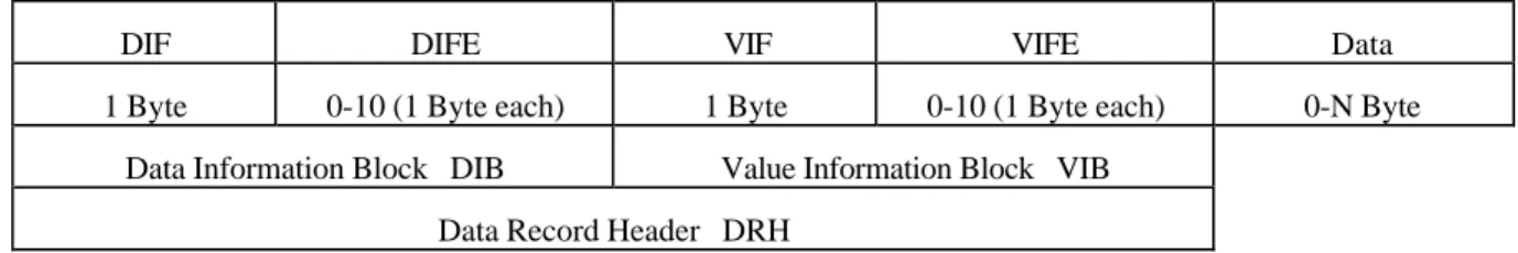
DIF DIFE VIF VIFE Data
1 Byte 0-10 (1 Byte each) 1 Byte 0-10 (1 Byte each) 0-N Byte
Data Information Block DIB Value Information Block VIB Data Record Header DRH
Fig. 4 Structure of a Data Record (transmitted from left to right)
Each data record contains one value (data) with its description (DRH). The DRH in turn consists of the DIB (data information block) to describe the length, type and coding of the data, and the VIB (value information block) to give the value of the unit and the multiplier.
4.1 Data Information Block (DIB)
The DIB contains at least one byte (DIF, data information field), and can be extended by a maximum of ten DIFE's (data information field extensions).
4.2 Data Information Field (DIF)
The following information is contained in a DIF:
Bit 7 6 5 4 3 2 1 0 Extension Bit LSB of storage number
Function Field Data Field :
Length and coding of data
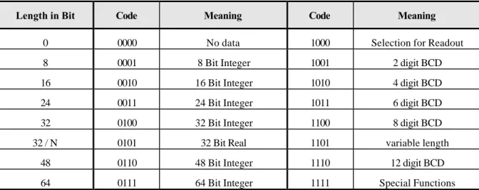
4.3 Data Field
The data field shows how the data from the master must be interpreted in respect of length and coding. The following table contains the possible coding of the data field:
Length in Bit Code Meaning Code Meaning
0 0000 No data 1000 Selection for Readout
8 0001 8 Bit Integer 1001 2 digit BCD
16 0010 16 Bit Integer 1010 4 digit BCD
24 0011 24 Bit Integer 1011 6 digit BCD
32 0100 32 Bit Integer 1100 8 digit BCD
32 / N 0101 32 Bit Real 1101 variable length
48 0110 48 Bit Integer 1110 12 digit BCD
64 0111 64 Bit Integer 1111 Special Functions
Table 6 Coding of the data field
Note that this table has been expanded with optional elements from the original standard.
For a detailed description of data types refer to appendix A”Coding of data records” (e.g. BCD = Type A, Integer = Type B, Real = Type H).
Variable Length:
With data field = `1101b` several data types with variable length can be used. The length of the data is given after the DRH with the first byte of real data, which is here called LVAR (e.g. LVAR = 02h: ASCII string with two characters follows).
LVAR = 00h .. BFh : 8-bit text string according to ISO 8859-1 with LVAR characters LVAR = C0h .. C9h : positive BCD number with (LVAR - C0h) • 2 digits
LVAR = D0h .. D9H : negative BCD number with (LVAR - D0h) • 2 digits LVAR = F8h : floating point number according to IEEE 754
Others LVAR values : Reserved
Like all multibyte fields the last character is transmitted first.
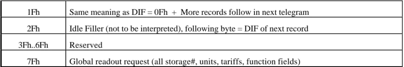
Special Functions (data field = 1111b):
DIF Function
1Fh Same meaning as DIF = 0Fh + More records follow in next telegram 2Fh Idle Filler (not to be interpreted), following byte = DIF of next record 3Fh..6Fh Reserved
7Fh Global readout request (all storage#, units, tariffs, function fields) Table 7: DIF-coding for special functions
Note that this table has been expanded with optional elements from the original standard.
If data follows after DIF=0Fh or 1Fh these are manufacturer specific unstructured data. The number of bytes in these manufacturer specific data can be calculated from the link layer information on the total length of the application layer telegram. The DIF 1Fh signals a request from the slave to the master to readout the slave once again. The master must readout the slave until there is no DIF=1Fh inside the respond telegram (multi telegram readout) or use an application reset.
4.4 Function field
The function field gives the type of data as follows:
Code Description Code Description
00b Instantaneous value 01b Maximum value
10b Minimum value 11b Value during error state
Table 8: Function Field
4.5 Storage number
The Bit 6 of the DIF serves as the LSB of the storage number of the data concerned, and the slave can in this way indicate and transmit various stored metering values or historical values of metering data. This bit is the least significant bit of the storage number and allows therefore the storage numbers 0 and 1 to be coded. If storage numbers higher than “1” are needed, following (optional) DIFE´s contain the higher bits. The storage number 0 signals an actual value. Note that a each storage number is associated with a given time point. So all data records with the same storage number refer to the value of the associated variable at this (common) time point for this storage number. It is recommended, that a time/date record with this storage number is included somewhere to signal this time point. Normally (but not necessarily) higher storage numbers indicate an older time point. A sequential block of storage numbers can be associated with a sequence of equidistantly spaced time points (profile). Such a block can be described by its starting time, by the time spacing, by the first storage number of such a block and by the length of such a block. The coding for such a block description in contrast to an individual time/date record for each individual storage number is given in the appendix.
4.6 Extension Bit
The extension bit (MSB) signals that more detailed or extended descriptions (data field extension=DIFE)-bytes follow.
4.7 Data field extension byte(s) (DIFE)
Each DIFE (maximum ten) contains again an extension bit to show whether a further DIFE is being sent. Besides giving the next most significant bits of the storage number, DIFE´s allow the transmission of information about the tariff and the subunit of the device . In this way, exactly as with the storage number, the next most significant bit or bits will be transmitted. The figure 8 which follows shows the structure of a DIFE:
Bit 7 6 5 4 3 2 1 0
Extension Bit
(Device) Unit
Tariff Storage Number
Fig. 5 Coding of the Data Information Field Extension (DIFE)
With the maximum of ten DIFE´s which are provided, there are 41 bits for the storage number, 20 bits for the tariff, and 10 bits for the subunit of the meter. There is no application conceivable in which this immense number of bits could all be used.
4.8 Tariff information
For each (unique) value type designation given by the following value information block (VIB) at each unique time point (given by the storage number) of each unique function (given by the function field) there might exist still various different data, measured or accumulated under different conditions. Such conditions could be time of day, various value ranges of the variable (i.e. separate storage of positive accumulatad values and negative accumulated values) itself or of other signals or variables or various averaging durations. Such variables which could not be distinguished otherwise are made different by assigning them different values of the tariff variable in their data information block. Note that this includes but is not necessarily restricted to various tariffs in a monetary sense. It is at the distinction of the manufacturer to describe for each tariff (except 0) what is different for each tariff number. Again as with the storage numbers all variables with the same tariff information share the same tariff associating condition.
4.9 Subunit information
A slave component may consist of several functionally and logically independent subunits of the same or of different functionallity. Such a device may either use several different primary and/or secondary adresses. Such it is from a link layer and an application layer view just several independent devices which share a common physical layer interface. This is recommended for devices which represent a physical collection of several truely
independent (often similar or idential) devices. For devices which share common information and values and have logical connections an approach with a common link layer (i.e.a single address) is reccomended. The various subunits can include their specific information into a common telegram and have them differentiated by the individual subunit number in the subunit-datafield of their records.
5 Value Information Block (VIB)
After a DIF (with the the exception of 0xFh) or a DIFE without a set extension bit there follows the VIB (value information block). This consists at least of the VIF (value information field) and can be expanded with a maximum of 10 extensions (VIFE). The VIF and also the VIFE's show with a set MSB that a VIFE will follow. In the value information field VIF the other seven bits give the unit and the multiplier of the transmitted value.
Bit 7 6 5 4 3 2 1 0
Extension Bit
Unit and multiplier (value)
Fig. 6 Coding of the Value Information Field (VIF)
There are five types of coding depending on the VIF:
a) Primary VIF: E000 0000b .. E111 1011b
The unit and multiplier is taken from the table for primary VIF (Table 9).
b) Plain-text VIF: E111 1100b
In case of VIF = 7Ch / FCh the true VIF is represented by the following ASCII string with the length given in the first byte. Please note that the byte order of the characters after the length byte depends on the used byte sequence. Since only the “LSB first mode” (M=1) of multibyte data transmission is recommended, the rightmost character is transmitted first. This plain text VIF allows the user to code units that are not included in the VIF tables.
c) Linear VIF-Extension: FDh and FBh
In case of VIF = FDh and VIF = FBh the true VIF is given by the next byte (i.e. the first VIFE) and the coding is taken from the tables 11 respectively table 12 for secondary VIF (chapter 8.4.4). This extends the available VIF´s by another 256 codes.
d) Any VIF: 7Eh / FEh
This VIF-Code can be used in direction master to slave for readout selection of all VIF´s. See chapter 6.4.3.
e) Manufacturer specific: 7Fh / FFh
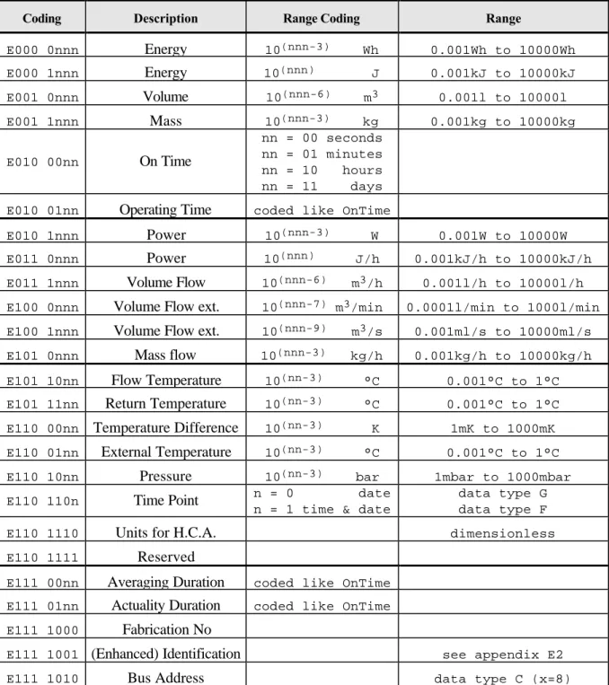
5.1 Primary VIF´s (main table)
The first section of the main table contains integral values, the second typically averaged values, the third typically instantaneous values and the fourth block contains parameters (E: extension bit).
Coding Description Range Coding Range
E000 0nnn
Energy
10(nnn-3) Wh 0.001Wh to 10000Wh E000 1nnnEnergy
10(nnn) J 0.001kJ to 10000kJ E001 0nnnVolume
10(nnn-6) m3 0.001l to 10000l E001 1nnnMass
10(nnn-3) kg 0.001kg to 10000kg E010 00nnOn Time
nn = 00 seconds nn = 01 minutes nn = 10 hours nn = 11 days E010 01nnOperating Time
coded like OnTimeE010 1nnn
Power
10(nnn-3) W 0.001W to 10000W E011 0nnnPower
10(nnn) J/h 0.001kJ/h to 10000kJ/h E011 1nnnVolume Flow
10(nnn-6) m3/h 0.001l/h to 10000l/h E100 0nnnVolume Flow ext.
10(nnn-7) m3/min 0.0001l/min to 1000l/min E100 1nnnVolume Flow ext.
10(nnn-9) m3/s 0.001ml/s to 10000ml/s E101 0nnnMass flow
10(nnn-3) kg/h 0.001kg/h to 10000kg/h E101 10nnFlow Temperature
10(nn-3) °C 0.001°C to 1°C E101 11nnReturn Temperature
10(nn-3) °C 0.001°C to 1°C E110 00nnTemperature Difference
10(nn-3) K 1mK to 1000mK E110 01nnExternal Temperature
10(nn-3) °C 0.001°C to 1°C E110 10nnPressure
10(nn-3) bar 1mbar to 1000mbar E110 110nTime Point
n = 0 daten = 1 time & date
data type G data type F
E110 1110
Units for H.C.A.
dimensionlessE110 1111
Reserved
E111 00nn
Averaging Duration
coded like OnTime E111 01nnActuality Duration
coded like OnTime E111 1000Fabrication No
E111 1001
(Enhanced) Identification
see appendix E2E111 1010
Bus Address
data type C (x=8)Table 9: Primary VIF-codes
5.2 VIF-Codes for special purposes:
Coding
Description
Purpose
1111 1011
Extension of VIF-codes
true VIF is given in the first VIFE and is coded using
table 10) (128 new VIF-Codes)
E111 1100
VIF in following string
(length in first byte)
allows user definable VIF´s (in plain ASCII-String) *
1111 1101
Extension of VIF-codes
true VIF is given in the first VIFE and is coded using
table 11) (128 new VIF-Codes)
E111 1110
Any VIF
used for readout selection of all VIF´s
(see chapter 9.2 )
E111 1111
Manufacturer Specific
VIFE´s and data of this block are manufacturer specific
Table 10: Special VIF-CodesNote that this table has been expanded with optional elements from the original standard.Note:
∗ Coding the VIF in an ASCII-String in combination with the data in an ASCII-String (datafield in DIF = 1101 b) allows the representation of data in a free user defined form.
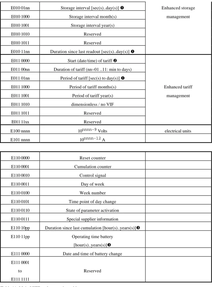
5.3 Main VIFE-Code Extension table (following VIF=FDh for primary VIF)
Coding Description Group
E000 00nn
Credit of 10nn-3 of the nominal local legal currency units
Currency Units E000 01nn
Debit of 10nn-3 of the nominal local legal currency units
E000 1000 Access Number (transmission count)
E000 1001 Device type
E000 1010 Manufacturer
E000 1011 Parameter set identification Enhanced Identification
E000 1100 Model / Version
E000 1101 Hardware version #
E000 1110 Metrology (firmware) version #
E000 1111 Other software version #
E001 0000 Customer location
E001 0001 Customer
E001 0010 Access Code User
E001 0011 Access Code Operator Improved Selection
E001 0100 Access Code System Operator and other user requirements
E001 0101 Access Code Developer
E001 0110 Password
E001 0111 Error flags (binary) (Device type specific)
E001 1000 Error mask
E001 1001 Reserved
E001 1010 Digital Output (binary)
E001 1011 Digital Input (binary)
E001 1100 Baudrate [Baud]
E001 1101 response delay time [bittimes]
E001 1110 Retry
E001 1111 Reserved
E010 0000 First storage # for cyclic storage E010 0001 Last storage # for cyclic storage
E010 0010 Size of storage block
E010 01nn Storage interval [sec(s)..day(s)] ΠEnhanced storage
E010 1000 Storage interval month(s) management
E010 1001 Storage interval year(s)
E010 1010 Reserved
E010 1011 Reserved
E010 11nn Duration since last readout [sec(s)..day(s)] Œ E011 0000 Start (date/time) of tariff •
E011 00nn Duration of tariff (nn=01 ..11: min to days) E011 01nn Period of tariff [sec(s) to day(s)] Œ
E011 1000 Period of tariff months(s) Enhanced tariff
E011 1001 Period of tariff year(s) management
E011 1010 dimensionless / no VIF
E011 1011 Reserved
E011 11xx Reserved
E100 nnnn 10nnnn-9 Volts electrical units
E101 nnnn 10nnnn-12 A
E110 0000 Reset counter
E110 0001 Cumulation counter
E110 0010 Control signal
E110 0011 Day of week
E110 0100 Week number
E110 0101 Time point of day change
E110 0110 State of parameter activation E110 0111 Special supplier information
E110 10pp Duration since last cumulation [hour(s)..years(s)]Ž
E110 11pp Operating time battery
[hour(s)..years(s)]Ž E111 0000 Date and time of battery change E111 0001
to E111 1111
Reserved
Table 11: Main VIFE-code extension table
Note that this optional table has been added to the original standard. Notes:
01 minute(s)
10 hour(s)
11 day(s)
• The information about usage of data type F (date and time) or data type G (date) can be derived from the datafield (0010b: type G / 0100: type F).
Ž pp = 00 hour(s)
01 day(s)
10 month(s)
11 year(s)
5.4 Alternate VIFE-Code Extension table (following VIF=0FBh for primary VIF)
Coding Description Range Coding Range
E000 000n Energy 10(n-1) MWh 0.1MWh to 1MWh E000 001n Reserved E000 01nn Reserved E000 100n Energy 10(n-1) GJ 0.1GJ to 1GJ E000 101n Reserved E000 11nn Reserved E001 000n Volume 10(n+2) m³ E001 001n Reserved E001 01nn Reserved E001 100n Mass 10(n+2) t 100t to 1000t
E001 1010-E010 0000 Reserved
E010 0001 Volume 0,1 feet^3
E010 0010 Reserved for Volume 0,1 USgallon Note 1 E010 0011 Reserved for Volume 1 USgallon Note 1 E010 0100 Reserved for Volume
flow
0,001 Usgallon/min Note 1
E010 0101 Reserved for Volume flow
1 Usgallon/min Note 1
E010 0110 Reserved for Volume flow
1 USgallon/h Note 1
E010 100n Power 10(n-1) MW
0.1MW to 1MW
E010 101n Reserved
E010 11nn Reserved
E011 000n Power 10(n-1) GJ/h 0.1GJ/hto 1GJ/h E011 0010-E101 0111 Reserved
E101 10nn Reserved for Flow Temperature
10(nn-3) °F
0.001°F to 1°F Note 1 E101 11nn Reserved for Return
Temperature
10(nn-3) °F
0.001°F to 1°F Note 1 E110 00nn Reserved for
Temperature Differ.
10(nn-3) °F
0.001°F to 1°F Note 1 E110 01nn Reserved for Flow
Temperature 10(nn-3) °F 0.001°F to 1°F Note 1 E110 1nnn Reserved
E111 00nn Reserved for Cold/Warm Temp. Lim.
10(nn-3) °F
0.001°F to 1°F Note 1 E111 01nn Cold/Warm Temp. Lim. 10(nn-3)
°C
0.001°C to 1°C
E111 1nnn Cum.Count Max.power 10(nnn-3) W 0.001W to 10000W Table 12: Alternate extended VIF-code Table
Note that this optional table has been added to the original standard. Note 1: These codes shall not be used in new developments. For non metric units in new developments use the corresponding metric unit and append the VIFE 3Dh (alternate unit, see table 13) and apply the unit translation table of appendix C.
5.5 Combinable (Orthogonal) VIFE-Code Extension table (Following primary VIF)
VIFE-Code Description
E00x xxxx Reserved for object actions (master to slave): see chapter 6.3 and table 16 or for error codes (slave to master): see chapter 7 and table 17
E010 0000 per second
E010 0001 per minute
E010 0010 per hour
E010 0011 per day
E010 0101 per month
E010 0110 per year
E010 0111 per revolution / measurement
E010 100p increment per input pulse on input channel #p E010 101p increment per output pulse on output channel #p E010 1100 per liter
E010 1101 per m3
E010 1110 per kg
E010 1111 per K (Kelvin)
E011 0000 per kWh
E011 0001 per GJ
E011 0010 per kW
E011 0011 per (K*l) (Kelvin*liter) E011 0100 per V (Volt)
E011 0101 per A (Ampere) E011 0110 multiplied by sek E011 0111 multiplied by sek / V E011 1000 multiplied by sek / A E011 1001 start date(/time) of Υ
E011 1010 VIF contains uncorrected unit instead of corrected unit E011 1011 Accumulation only if positive contributions
E011 1100 Accumulation of abs value only if negative contributions E011 1101
Reserved for alternate non-metric unit system (See appendix C)
E011 111x
Reserved
E100 u000 u=1: upper, u=0: lower limit value
E100 u001 # of exceeds of lower u=0) / upper (U=1) limit
E100 uf1b Date (/time) of: b=0: begin, b=1: end of, f=0: first, f=1: last,• u=0: lower, u=1: upper limit exceed
E101 ufnn Duration of limit exceed (u,f: as above, nn=duration) E110 0fnn Duration of Π(f: as above, nn=duration)
E110 1u00 Value during lower (u=0), upper (u=1) limit exceed
E1101x01 Reserved
E110 1f1b Date (/time) of Υ (f,b: as above) E111 0nnn Multiplicative correction factor: 10nnn-6
E111 1100 Reserved
E111 1101 Multiplicative correction factor for value (not unit): 103 E111 1110 future value
E111 1111 next VIFE's and data of this block are maufacturer specific
Table 13: Combinable (orthogonal) VIFE-Table
Note that this optional table has been added to the original standard.
Notes:
Œ ”Date(/time) of” or ”Duration of” relates to the information which the whole data record header contains.
• The information about usage of data type F (date and time) or data type G (date) can be derived from the datafield (0010b: type G / 0100: type F).
6 Application Layer Status and error reporting
The data link layer reports only communication errors by means of omitting the acknowledgement E5h. It is not allowed to report errors of the application layer (which can occur for example in data writing) via the link layer. The slave can transmit an 0E5h after a SND_UD to indicate that it has received the telegram, but can´t respond with data. There are three different techniques for reporting application errors:
6.1 Status Field
One possible solution is to use the reserved 2 lowest bits of the Status field in the variable data structure for the application layer status (see Table 6).
6.2 General Application Layer Errors
For reporting general application errors a slave can use a RSP_UD telegram with CI=70h and zero, one or several data bytes, which then describes the type of error:
68h 04h 04h 68h 08h PAdr 70h DATA CS 16h
Fig. 11 Telegram for reporting general application errors
The following values for DATA are defined:
0
Unspecified error: also if data field is missing
3
Too many records
4
Premature end of record
5
More than 10 DIFE´s
6
More than 10 VIFE´s
7
Reserved
8
Application too busy for handling readout request
9
Too many readouts (for slaves with limited readouts per time)
10..255
Reserved
Table 15 Codes for general application errors
Note that this optional table has been added to the original standard.
6.3 Record Errors
To report errors belonging to a special record the slave can use this data record header with a VIFE containing one of the following values to code the type of application error, which has been occured.
VIFE-Code
Type of Record Error
Error Group
E000 0000 None
E000 0001 Too many DIFE´s
E000 0010 Storage number not implemented E000 0011 Unit number not implemented
E000 0100 Tariff number not implemented DIF Errors
E000 0101 Function not implemented E000 0110 Data class not implemented E000 0111 Data size not implemented E000 1000 to
E000 1010 Reserved E000 1011 Too many VIFE´s E000 1100 Illegal VIF-Group
E000 1101 Illegal VIF-Exponent VIF Errors
E000 1110 VIF/DIF mismatch E000 1111 Unimplemented action E001 0000 to
E001 0100 Reserved
E001 0101 No data available (undefined value) E001 0110 Data overflow
E001 0111 Data underflow
E001 1001 to
E001 1011 Reserved
E001 1100 Premature end of record E001 1101
to E001 1111
Reserved Other Errors
Table 16: Codes for record errors (E = extension bit)
Note that this optional table has been added to the original standard.
In case of record errors the data maybe invalid. The slave has some options to transmit the data:
• datafield = 0000b: no data
• datafield = 0000b: no data and idle filler (DIF=02Fh): fill record up to the normal length
• other datafield: dummy data of correct length
• other datafield: unsafe or estimated data
7 Generalized Object Layer
The fundamental idea of an object is the encapsulation of data and methods or actions for the data. In case of writing data to a slave the master software can pack data and information about the action, which the slave shall do with this data, in one data record. This variable data record with actions is now called an object. Following any VIF including a VIF=FDh or VIF=0FBh with the true value information in the first VIFE another (usually the last) VIFE can be added which contains a code signalling object actions according to the following table.
Action: (E: extension bit)
VIFE-Code binary Action Explanation
E000 0000 Write (Replace) replace old with new data
E000 0001 Add Value add data to old data
E000 0010 Subtract Value subtract data from old data
E000 0011 OR (Set Bits) data OR old data
E000 0100 AND data AND old data
E000 0101 XOR (Toggle Bits) data XOR old data
E000 0110 AND NOT (Clear Bits) NOT data AND old data
E000 0111 Clear set data to zero
E000 1000 Add Entry create a new data record
E000 1001 Delete Entry delete an existing data record
E000 1010 Delayed Action A CI=5Ch will follow and execute the desired action
E000 1011 Freeze Data freeze data to storage no.
E000 1100 Add to Readout-List add data record to RSP_UD
E000 1101 Delete from Readout-List delete data record from RSP_UD
E000 111x Reserved
E001 xxxx Reserved
Table 17: Action Codes for the Generalized Object layer (Master to Slave) Note that this optional table has been added to the original standard.
Note:
The object action "write / replace" (VIFE = E000 0000) is the default and is assumed if there is no VIFE with an object action for this record.
8 Manufacturer Specific unstructured Data Block
The MDH consists of the character 0Fh or 1Fh (DIF = 0Fh or 1Fh) and indicates that all following data are manufacturer specific. When the total number of bytes given from the link/network layers and the number of record-structured bytes and the length of the fixed header is known, the number of remeining unstructured manufacturer specific bytes can be calculated.
Note that stuctured manufacturer specific data (i.e. those with a known data structure including variable length binary or ASCII but with a manufacturer specific meaning or unit) can be described using normal data records with a value information field of VIF=E1111111b.
In case of MDH = 1Fh the slave signals to the master that it wants to be readout once again (multitelegram readouts). The master must readout the data until there is no MDH = 1Fh in the respond telegram.
9 Management of lower layers
Because changing of parameters like baudrate and address by higher layers is not allowed in the ISO-OSI-Model, a Management Layer beside and above the three layers of the collapsed model is defined:
MANAGEMENT LAYER
Application Layer
Data Link Layer Secondary adresss selection via address 253 and CI=52h
Physical Layer Address 254 (255)/251
So the address 254 and perhaps 255 can be used also for managing the physical layer of the bus and the adress 251 is reserved for managing the (primary) M-Bus level converter/bridge and the address 253 (selection) for network layer (see chapter 7), which is only used in certain cases. With such a managment addresses and or CI-fields we can directly manage each OSI-layer to implement features, which are beyond the elementary OSI-Model.
9.1 Switching Baudrate
All slaves must be able to communicate with the master using the minimum transmission speed of 300 baud. Split baudrates between transmit and receive are not allowed, but there can be devices with different baudrates on the bus.
In point to point connections the slave is set to another baudrate by a Control Frame (SND_UD with L-Field = 3) with address FEh and one of the following CI-Field codes: Note that for safety reasons a baudrate switch command to the (unacknowledged) broadcast adress 255 is not recommended.
CI-Field B8h B9h BAh BBh BCh BDh BEh BFh
Baud 300 600 1200 2400 4800 9600 19200 38400
Note 1 2 2 1 2 1 2 2
Fig. 33 CI-Field-Codes for Baudrate Switching
Notes:
1) Recommended standard baudrates
2) These baudrates are reserved for special operator agreement only and should be avoided..
The slave always confirms the correctly received telegram by transmitting an E5h with the old baudrate and uses the new baudrate from now on, if he is capable of this. Otherwise the slave stays at its previous baudrate after the 0E5h acknowledge. To make sure that a slave without autospeed detect has properly switched to the new baudrate and that it can communicate properly at the new baudrate in its segment it is required that after a baudrate switch to a baudrate other than 300 Baud the master attempts imediately (<2min) after the baudrate switch command a communication. If (even after the appropriate number of retries) this is not acknowledged by the slave, the master shall issue a baudrate set command (at the attempted new baudrate) back to the previous baudrate. If a slave without autospeed detect does not receive a valid communication at the new baudrate within 2-10 minutes of the baudrate switch command the slave must fall back to its previous baudrate. This is required individually and sequentially for each adressable slave. For compatibility with older slaves with fallback to 300 baud the master should also attempt a communication at 300 baud if the slave does not answer at its last baudrate.
9.2 Selection and Secondary Addressing
This technique allows the M-Bus protocol to logically "connect" a slave with a certain (secondary) address and it then associates this selected slave with the primary address of 253 (FDh). So the maximum number of 250 addresses (primary) is extended by this technique to an arbitrary number of possible slaves, effectively increasing the address range of the link layer. This function is only enabled by a SND_UD with CI_Field 52h to address 253.
When addressing in the data link layer with the help of the A-Field, the problem of the address allocation could arise. The addresses are normally set to a value of 0 by the manufacturer of the meters, in order to designate them as unconfigured slaves. A very laborious method of address allocation consists of setting the addresses when installing the slaves, for example with DIP switches. A further method of address allocation is to determine the bus addresses when connecting the equipments to the bus with the master software. This sends a command for address allocation (see Appendix E2) to the address 0. In this case the slaves must however all be successively connected to the bus, which very much gets in the way of a simple installation procedure.
When however addressing in the network layer these disadvantages are avoided and the address region is essentially extended beyond the number of 250 with primary addressing (A-Field). The addressing of the slaves takes place with secondary addressing with the help of the following so-called selection:
68h 0Bh 0Bh 68h 53h FDh 52h ID1-4 Man 1-2 Gen Dev CS 16h
Fig. 44 Structure of a telegram for selecting a slave
The master sends a SND_UD with the control information 52h to the address 253 (FDh) and fills the specific meter secondary address (identification number, manufacturer, version and device type) with the values of the slave which is to be addressed. After the reception of the address FDh the selection mode is entered. If then the proper CI-selection code CI=52h, is received the internal selection bit is set otherwise it is reset. If further data bytes follow they are compared with the corresponding internal addresses respective values of the meter. If they disagree, the selection bit is cleared otherwise it is left unchanged. Thus “selecting” a meter with only a proper CI-field and no further data will select all meters on the bus capable of secondary addressing. A set selection bit means that this slave can be addressed (e.g. REQ_UD) with the bus address FDh and in this example will reply with RSP_UD. In other words the network layer has associated this slave with the address FDh.
During selection individual positions of the secondary addresses can be occupied with wildcards (Fh). Such a Wildcard means that this position will not be taken account of during selection, and that the selection will be limited to specific positions, in order to address complete groups of slaves (Multicasting). In the identification number each individual digit can be wildcarded by a wildcard nibble Fh while the fields for manufacturer, version and device type can be wildcarded by a wildcard byte FFh.
The state of the selection remains unchanged until the slave is deselected with a selection command (as described above) with non-matching secondary addresses, or a SND_NKE to address 253. The slave, which uses
mode 1 for multibyte records, will be selected by a telegram with the CI-Field 52h and the correct secondary address, but it will be deselected by a telegram with any other secondary address.
A slave with implemented primary and secondary addressing should also answer telegrams to his primary address. A slave with only secondary addressing (i.e. internal primary address=253) should occupy the address field in the RSP_UD telegram with FDh to signal that it will not participate in primary addressing.
9.3 Generalized Selection Procedure
For including new or restructed identification parameters into a selection procedure an enhanced definition of the selection telegram (CI=52h) can be used:
After the 8 byte of the fixed selection header may also follow standard records with data. In this case only those meters will be selected, where in addition to the fixed header all record data agree. In most but not all cases this means that the DIF and parts of the VIF (not exponent) must match. Again wildcard rules apply to the record data (digit wildcard for BCD-coded data and byte wildcard for binary or string data).
With this generalized selection it will be possible to select slaves using e.g. additional fabrication number, longer identification numbers, customer, customer location and more information. For inclusion of the fabrication number in the selection process
after the field “device type” the 8-digit BCD-fabrication number follow. Parts of the fabrication number (Fab1..Fab4) can be occupied with wildcards (Fh).
If a fabrication number exists the slave should add this data to the variable data blocks in every RSP-UD telegram. If the fabrication number and enhanced selection is not implemented in a slave this device will not confirm the enhanced selection telegram and will be deselected.
Enhanced selection should be used only if the normal kind of selection is not successful.
Enhanced selection with fabrication number
The identification number can be used as a customer number and then can be changed by the operator. Therefore it can be possible that two slaves have the same secondary adress. For this reason the selection telegram can be extended by a fabrication number to make sure that in any case all slaves are distinguishable. This number is a serial number allocated during manufacture, coded with 8 BCD packed digits (4 Byte) like the identification number, and thus runs from 00000000 to 99999999.
The following figure shows the structure of an enhanced selection telegram released by the master.
68h 11h 11h 68h 53h FDh 52h ID1-4 Man1-2 Gen Med 0Ch 78h Fab1-4 CS 16h
Fig. 55 Structure of a telegram for enhanced selection (mode 1)After the field medium the new data is given in form of a structured datarecord with DIF=0Ch and VIF=78h. Parts of the fabrication number (Fab1..Fab4) can be occupied with wildcards (Fh).
If a fabrication number exists the slave should add this data to the variable data blocks in every RSP-UD telegram. If the fabrication number and enhanced selection is not implemented in a slave this device will not confirm the enhanced selection telegram and will be deselected.
Enhanced selection should be used only if the normal kind of selection is not successful.
9.4 Searching for Installed Slaves
9.4.1 Primary Addresses
To read out all installed slaves the master software must know all the slaves, which are connected to the bus. Therefore the software searches for slaves with primary adressing by sending a REQ_UD2 to all allowed adresses (1..250) with all available baudrates. The master notes used primary addresses with the respective baudrates.
9.4.2 Secondary Addresses
The secondary addressing described in the preceding section draws attention to the problem of determining the secondary addresses of slaves connected to the bus. The master can after this read out the slaves making use of secondary addresses with previous selection. Testing all possible identification numbers with the master software would take years, since the identification number offers millions of combinations. For this reason, a procedure was developed for the rapid and automatic determination of already installed slaves:
9.4.3 Wildcard searching procedure
The following wildcard searching procedure uses the occupation of individual parts of the secondary address with wildcards (Fh) for selection:
In this case with the identification number (BCD) each individual position, and by manufacturer, version and medium (binary coding), only one complete byte, can be occupied with wildcards. The master begins the selection using a SND_UD with the control information 52h (Mode 1), and occupies all positions in the identification number, except the top one, with wildcards. The top position is run through in ten selections from 0 to 9 (0FFFFFFF to 9FFFFFFF).
If after such a selection the master receives no acknowledgement, it then goes to the next selection. If the master receives an E5h, it then sends a REQ_UD2 and learns the secondary address of the slaves from the reply telegram, as long as no collision occurs. If there is a collision after the selection or the REQ_UD2, the master varies the next positions and holds the existing one. If there is a collision, for example at 5FFFFFFF, the selection is run through from 50FFFFFF to 59FFFFFF. If in this case collisions again occur, then a change is made to a variation of the next position. After running through a complete position, the next higher position is processed up to 9.
With this Wildcard searching procedure, it will be seen that at least the top position must be run through in order to reach all slaves. Running through further positions may be necessary, depending on the number of the slaves and the distribution of the identification numbers. This procedure allows a statement of the maximum number of selections in relation to the number of slaves, but as disadvantage frequent collisions, which occur, should be mentioned. The wildcard searching procedure must be performed for all used baudrates and both byte sequences (mode 1 and 2).
The search procedure can be extended with searching for manufacturer, generation and finally device types to find slaves, which have the same identification number. It is also possible to search for all slaves of a certain manufacturer or all slaves of a certain device type by setting the corresponding value. With extended selection meters which differ only in their manufacturer specific fixed fabrication number can be distinguished.
Appendix A: Coding of Data Records (Normative)
The following data types are used inside the application layer:Type A = Unsigned Integer BCD := XUI4 [1 to 4] <0 to 9 BCD>
27 26 25 24 23 22 21 20
digit 10 digit 1 1UI4 [1 to 4] <0 to 9 BCD> := digit 100 8 4 2 1 8 4 2 1 2UI4 [5 to 8] <0 to 9 BCD> := digit 101
... ... ... ... ... ... ... ... ...
8 4 2 1 8 4 2 1 XUI4 [5 to 8] <0 to 9 BCD> := digit 10X-1
Digits values of Ah-Eh in any digit position signals invalid.
A hex code Fh in the MSD position signals a negative BCD number in the remaining X-1 digits. For details of this coding see appendix B.
Type B = Binary Integer := I[1..X] <(-2X-1 -1) to +(2X-1-1)>
27 26 25 24 23 22 21 20 1B1 [X] := S=Sign: S<0> := positive
... ... S<1> := negative
S 2X-2 2X-8 negative values in two´s complement
The coding “10000000b” signals “invalid”
Type D = Boolean (1 bit binary information) := XB1 B1[i] <0 to 1>
27 26 25 24 23 22 21 20 XB1: B1[i] <0 to 1>
... ... B1[i] <0> := false
2X-1 2X-8 B1[i] <1> := true
Type E = Obsolete
Type G: Compound CP16: Date
27 26 25 24 23 22 21 20 day: UI5 [1 to 5] <1 to 31> “0”: every day 215 214 213 212 211 210 29 28 month: UI4 [9 to 12] <1 to 12>
“15”: every month
year: UI7[6 to 8,13 to 16] <0 to 99> 127: every year
For compatibility with old meters with a circular two digit date it is recommended to consider in any master software the years “00” to “80” as the years 2000 to 2080.
Type H: Floating point according to IEEE-standard
"Short floating Point Number IEEE STD 754" = R32IEEESTD754 R32IEEESTD754 := R32.23 {Fraction, Exponent, Sign}
Fraction = F := UI23 [1to 23] <0 to 1-2-23> Exponent = E := UI8 [24 to 31] <0 to 255> Sign = S := BS1 [32] S<0> = positive
S <1> = negative
F <0> and E <0> := (-1) S ∗ 0 = ± zero F <≠0> and E <0> := (-1) S ∗ 2E-126(0.F) = denormalized numbers E <1 to 254> := (-1) S ∗ 2E-127(1.F) = normalized numbers F <0> and E <255> := (-1) S ∗∞ = ± infinite
F <≠0> and E <255> := NaN = not a number, regardless of S
bits 8 7 6 5 4 3 2 1
27 26 25 24 23 22 21 20 215 214 213 212 211 210 29 28 223 222 221 220 219 218 217 216 231 230 229 228 227 226 225 224
octet 1 F = Fraction 2-16 2-17 2-18 2-19 2-20 2-21 2-22 2-23 octet 2 F = Fraction 2-8 2-9 2-10 2-11 2-12 2-13 2-14 2-15 octet 3 E (LSB) F = Fraction 2-0 2-1 2-2 2-3 2-4 2-5 2-6 2-7
octet 4 Sign E = Exponent
S 27 26 25 24 23 22 21
The following ranges are specified by IEE Std 754-1985 for floating point arithmetics:
Range: (-2128 + 2104) to (+2128 - 2104), that is -3.4∗1038 to +3.4*1038 smallest negative number: -2-149, that is: -1.4∗10-45 smallest positive number: +2-149, that is: + 1.4∗10-45
Appendix B:
Normative Interpretation of Hex-Codes Ah-Fh in BCD-data fields
General description
1.) Standard Reference
This standard allows multi-digit BCD-coded datafields. It does however not contain information about what happens if a non-BCD hex code (Ah-Fh) is detected by the master software.
2.) Purpose of this proposal
a) Define the treatment of non BCD-digits in slave to master RSP_UD-telegrams
To fully define a master software including error treatment such a definition would be desirable. b) Utilize these codes for simplified error treatment by slave
• Simple visible error signalling
To simplify the design of slaves with integrated displays, the above mentioned non-BCD states of the variables should be both transmittable in the form of suitable (Hex) codes but also be displayable directly from the value codes of a 7-segment (usually LCD) display by extending the normal ten entry BCD to 7-segment decoding a 16-entry decoding table
Recommendation
a) Ah-Eh
Such a code in any digit position signals a general error of the complete data field. The display at the meter or a remote readout device should display an appropriate symbol at the appropriate display position.
b) Fh
Such a code in the MSD digit position signals a “minus-sign” in front of the remaining (N-1) digit number. In any other digit position it signals an error.
Example: A 4-digit BCD code of "F321" should be interpreted by the master software as "- 321" and displayed as -321 on a 4-digit only display.
2.) Recommended LCD-Decoding table a) Decoding table
1 2 3 4 5 6 7 8 9 Ah Bh Ch Dh Eh Fh
Appendix C: Non metric units (Normative)
If the VIF-Extension code 3Dh (Non-metric units) is used, the standard metric units of the VIF table is substituted as follows:
Standard VIF Standard unit and range Nonmetric unit and range Type
E0000nnn 0.001Wh to 10 000Wh 0.001kBTU to 10 000kBTU energy
E0010nnn 0.001l to 10 000l 0.001USgal to 10 000 USgal volume E1000nnn 0.001l/min to 10 000l/min 0.001 USgal/min to 10 000
USgal/min
Flow ext.
E0101nnn 0.001W to 10 000W 0.001mBTU/s to 10 000 mBtu/s Power
E10110nn 0.001°C to 1°C 0.001°F to 1°F Temp. forward
E10111nn 0.001°C to 1°C 0.001°F to 1°F Temp. return
E11101nn 0.001°C to 1°C 0.001°F to 1°F Cold/warm temperature
limit
E11000nn 0.001°C to 1°C 0.001°F to 1°F Temp. difference
Appendix D: Alarm Protocol (Recommendation)
The master software polls the maximum 250 alarm devices by requesting time critical data (REQ_UD1 to adresses 1 .. 250). A slave can transmit either a single character acknowledgement E5h signalling no alarm or a RSP_UD with the CI-Field 71h to report an alarm state.
68h 04h 04h 68h 08h Adr 71h Alarm State CS 16h
Fig. 66 Telegram for an Alarm-Respond
The alarm state is coded with data type D (boolean, in this case 8 bit). Set bits signal alarm bits or alarm codes. The meaning of these bits is manufacturer specific.
The timeout for time critical communication must be set to 11..33 bit periods to ensure a fast poll of all alarm devices. With a baudrate of 9600 Bd and all 250 slaves reporting an alarm just in time before a timeout occurs each slave will be polled in periods of maximum 5.5 seconds. This seems to be fast enough for alarms in building control systems and other applications. For faster alarm systems the number of alarm sensors could be limited to 63 (reducing the worst case overall signal delay to less than 1.5 sec or increase the transmission speed to 38400 Bd and achieve the same speed for up to 250 devices.
The functionality of the FCB- and FCV-Bit should be fully implemented in this alarm protocol to ensure that one-time alarms are safely transmitted to the master. If the slave has reported an one-one-time alarm and the next REQ_UD1 has a toggled FCB (with FCV=1) the slave will answer with an E5h signalling no alarm. Otherwise it will repeat the last alarm frame to avoid that the alarm message gets lost.
Appendix E: Examples
Example for a RSP_UD with variable data structure answer :
(all values are hex.)
68 1F 1F 68 header of RSP_UD telegram (length 1Fh=31d bytes) 08 02 72 C field = 08 (RSP), address 2, CI field 72H (var.,LSByte first) 78 56 34 12 identification number = 12345678
24 40 01 07 manufacturer ID = 4024h (PAD in EN 61107), generation 1, water 55 00 00 00 TC = 55h = 85d, Status = 00h, Signature = 0000h
03 13 15 31 00 Data block 1: unit 0, storage No 0, no tariff, instantaneous volume, 12565 l (24 bit integer)
DA 02 3B 13 01 Data block 2: unit 0, storage No 5, no tariff, maximum volume flow, 113 l/h (4 digit BCD)
8B 60 04 37 18 02Data block 3: unit 1, storage No 0, tariff 2, instantaneous energy, 218,37 kWh (6 digit BCD)
18 16 checksum and stopsign
Example baud rate switch:
The master switches the slave (in point to point connection) from now 2400 baud to 9600 baud. Master to slave: 68 03 03 68 | 53 FE BD | 0E 16 with 2400 baud
Slave to master: E5 with 2400 baud
From that time on the slave communicates with the transmission speed 9600 baud, if the slave can handle 9600 baud, otherwise it remains at 2400 baud.
In busmode this must be followed within < 2min by an acknowledged communication (i.e. SND_NKE) at 9600 baud:
Master to slave: 10 40 FE 3E 16 Slave to master: E5
Example Reset with subcode:
The master releases an enhanced application reset to all slaves. All telegrams of the user data type are requested.
Master to Slave: 68 04 04 68 | 53 FE 50 | 10 | B1 16 Slave to Master: E5
E.2 Writing Data to a Slave
The master can send data to a slave using a SND_UD with CI-Field 51h for mode 1 (or 55h for old mode 2-meters). Note that the data structure in such a write telegram has been changed in contrast to previous definitions by means of leaving out the fixed data header of 12 byte. The following figure shows the data structure for a write telegram. The order of the first three blocks in the following figure can be turned round, but the write only data record must be at the end of the telegram. All records are optional.
Primary Address Record Enhanced Identifica-tion Record
Normal Data Records
Write Only Data Records
Fig. 77 Data Structure for Writing Data • Primary Address Record:
The primary address record is optional and consists of three bytes:
DIF = 01h VIF = 7Ah Data = Address (1 byte binary)
With this data record a primary address can be assigned to a slave in point to point connections. The master must know all the used addresses on the bus and forbid setting the address of a slave to an already used address. Otherwise both slaves with the same address couldn´t be read out anymore.
• Enhanced Identification Record:
With this optional data record the identification (secondary address) can be changed. There are two cases to be distinguished:
1) Data is only the identification number
DIF = 0Ch VIF = 79h Data = Identification No. (8 digit BCD)
2) Data is the complete identification
DIF = 07h VIF = 79h Data = complete ID (64 bit integer)
The data is packed exactly as in the readout header of a 72 variable protocol with low byte first for mode 1 and high byte first for mode 2:
Identification No. Manufacturer ID Generation Medium
• Normal Data Records:
The data records, which can be read out with a REQ_UD2, are sent back to the slave with the received DIF and VIF and the new data contents. Additional features can be implemented using the generalized object layer (see chapter 6.5).
• Write-Only Data:
Data, which cannot be read out of the slave with a normal data block, can be transmitted using the VIF = 7Fh for manufacturer specific coding. The DIF must have a value corresponding to the type and length of data.
After receiving the SND_UD correctly without any error in data link layer the slave must answer with an acknowledgement (E5h). The slave decides whether to change variables or not after a data write from the master. In case of errors in executing parts of or whole write instructions the slave can decide whether to change no variables or single correct variables. The slave can report the this errors to the master in the next RSP_UD telegram using some of the methods which are described in chapter 6.6.
There are some methods for implementing write protect, for example allowing only one write after a hardware reset of the processor or enabling write if a protect disable jumper is set.
Examples:
1. Set the slave to primary address 8 without changing anything else: 68 06 06 68 | 53 FE 51 | 01 7A 08 | 25 16
2. Set the complete identification of the slave (ID=01020304, Man=4024h (PAD), Gen=1, Med=4 (Heat): 68 0D 0D 68 | 53 FE 51 | 07 79 04 03 02 01 24 40 01 04 | 95 16
3. Set identification number of the slave to "12345678" and the 8 digit BCD-Counter (unit 1 kWh) to 107 kWh. 68 0F 0F 68 | 53 FE 51| 0C 79 78 56 34 12 | 0C 06 07 01 00 00 | 55 16
E.3 Configuring Data Output
For default the slave transmits all his data with a RSP_UD. It could be useful for some applications to read only selected data records out of one or more devices. There are two ways to select data records:
Selection without specified data field
The selection of the wanted data records can be performed with a SND_UD (CI-Field = 51h/55h) and data records containing the data field 1000b, which means "selection for readout request". The following VIF defines the selected data as listed in EN1434-3 and no data are transmitted. The answer data field is determined by the slave. The master can select several variables by sending more data blocks with this data field in the same telegram.