The Sum-Absolute-Difference Motion Estimation Accelerator
S. Vassiliadis,
E.A. Hakkennes,
J.S.S.M. Wong
Electrical Engineering Dept.
Delft University of Technology
Mekelweg 4, 2628 CD Delft
The Netherlands
[email protected]
G.G. Pechanek
BOPS Inc.
6340 Quadrangle Drive
Suite 210
Chapel Hill, NC 27514
Abstract
In this paper we investigate the Sum Absolute Difference (SAD) operation, an operation frequently used by a number of algorithms for digital motion estimation. For such op-eration, we propose a single vector instruction that can be performed (in hardware) on an entire block of data in par-allel. We investigate possible implementations for such an instruction. Assuming a machine cycle comparable to the cycle of a two cycle multiply, we show that for a block of 16x1 or 16x16, the SAD operation can be performed in 3 or 4 machine cycles respectively. The proposed implemen-tation operates as follows: first we determine in parallel which of the operands is the smallest in a pair of operands. Second we compute the absolute value of the difference of each pairs by subtracting the smallest value from the largest and finally we compute the accumulation. The operations associated with the second and the third step are performed in parallel resulting in a multiply (accumulate) type of op-eration. Our approach covers also the Mean Absolute Dif-ference (MAD) operation at the exclusion of a shifting (di-vision) operation.
1. Introduction
In block-based motion estimation [10, 3], that is motion estimation performed on a set of pixels, every frame is di-vided into blocks of equal size and for each block in the
current frame a search is performed in the reference frame
to find the block resembling the current block the most. Be-cause a search performed over the whole reference frame for each block in the current frame is computational inten-sive and movements in video sequences are usually small, the search is limited to a search area. After finding the best match for the current block, the motion vector (i.e. the dis-placement relative to the current block) is stored together with the differences between the two blocks. In determining
which block in the searching area of the reference frame is the best match with the current frame, a best match method is employed. The best match is usually established with the use of the mean absolute difference (MAD) and the sum of
absolute differences (SAD).
In this paper our primary concern is to propose a hard-ware solution to the SAD and the MAD operations. That is our primary concern is to propose instructions that have “convenient” hardware implementations, where “conve-nient” in the context of our discussion mainly means paral-lel hardware vector related implementations. We note here that if the division (shifting) operation is excluded from the MAD then both operations can be viewed as equivalent. In essence, discussing the SAD operation will also cover the MAD with an additional shift (divide) of the final result, thus MAD is no longer considered in the discussion to fol-low.
Given that the SAD operation is usually considered for 16x16 pixels (pels) blocks [10] and because the search area could involve a high number of blocks, performing the SAD operation could be time-consuming if traditional methods are used for its computation1. In this paper we propose a
new instruction that is capable of producing the direct SAD operation. Furthermore we also show that the proposed in-struction is scalable, depending on the constraints of the technology considered for the design. This is shown by considering a 16x1 sub-block element and an entire 16x16 element and showing that the implementation will require 3 machine cycles2 for a 16x1 sub-block and 4 cycles for
a 16x16 block. The 16x16 block performance is achieved by using hardware proportional in size to a 16x1 sub-block unit, that is we achieve a 4 cycle 16x16 block SAD using
1Traditional here means that performing SAD requires a number of subtractions with proper complementation to produce the absolute value which are followed by an accumulation to perform the final operation.
2A cycle here is considered to be comparable to the cycle of a high-speed, 2-cycle, 32x32 bit multiplier [11, 17, 18]. Other implementations including array systolic implementations are also possible.
approximately 16 times the area of the 16x1 SAD.
The rest of this paper is organized as follows. Section 2 gives some background information about motion estima-tion and how it fits in the MPEG standard, followed by a discussion of the SAD operation. Section 3 describes the basic operation of our proposed Sum-Absolute-Difference unit, and Section 4 gives a sample implementation of the proposed unit. Section 5 concludes this paper with some remarks and future research directions.
2. Background
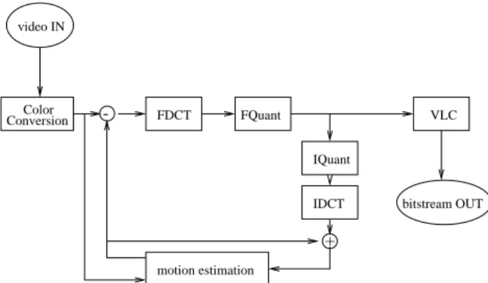
In MPEG [10, 4], video-sequences are compressed by exploiting both spatial and temporal redundancies. Spatial redundancies can be seen as small differences between local pels. In many encoding schemes the spatial redundancies are exploited using DCT [1, 7, 15] or predictive coding [12]. Temporal redundancies can be seen as small differences be-tween two temporally close video frames. These kind of redundancies can also be exploited using predictive coding, but more compression can be reached by using it together with motion compensation [6]. As an example, a diagram of the MPEG encoding process is given below. Because the MPEG standard does not specify the encoding process, this diagram is only one possible implementation for the MPEG encoding process. In the diagram, FDCT denotes the Forward Discrete Cosine Transformation, FQuant de-notes the Forward Quantization and VLC dede-notes Variable Length Coding. The IQuant and IDCT are the inverse oper-ations needed to reproduce the picture as it is available at the decoder. The motion estimation block uses these decoded images as reference instead of original images, because the decoder only has access to decoded images. Adding “differ-ences from original images” to decoded images which are already slightly different from the original images, would introduce unnecessary errors in the decoded images.
FDCT FQuant IQuant VLC bitstream OUT motion estimation ConversionColor IDCT -+ video IN
Figure 1. Diagram of a MPEG encoder imple-mentation.
In the MPEG coding, there are two kinds of blocks: the 16x16 (pels) macro-block and the 8x8 (pels) basic block. The basic block is used when the DCT is performed and the macro-block is used for motion estimation. The encoding of a video stream is done in several steps. Each of the steps depicted in Figure 1 are explained below. For simplicity, many details regarding the MPEG standard are left out.
Color conversion In this step the input color-space is
transformed into the YCbCr color-space. Furthermore, the chrominances are subsampled by a factor of two in both the horizontal and vertical direction. Thus, a 16x16 block from the video signal results in four 8x8 luminance blocks, one 8x8 Cb block, and one 8x8 Cr block. These 8x8 blocks are used by the DCT. The 16x16 luminance block is used by the motion estima-tion.
Motion Estimation In this step, for each block of 16x16
luminance pels in the current frame, a motion vector is computed. This motion vector contains the relative position of the block most closely resembling the cur-rent block in the reference frame (either in the past or future). To exploit redundancies between difference values, the difference values are also put through the DCT process.
Discrete Cosine Transformation In this step a DCT is
performed on each 8x8 blocks which can be either blocks from the frame or difference blocks.
Quantization In this step the DCT coefficients computed
in the DCT process are quantized. This step is the main contribution to the lossiness of the MPEG coding standard. However, the information lost in this step is thought to be (almost) not perceivable due to the use of the DCT. Depending on constraints on the bitstream rate, the quantization can be adjusted to meet these constraints which can result in lower quality video if the quantization is too coarse.
Variable Length Coding In this step the results of the
quantization process are serialized into a bitstream us-ing run-length codus-ing and variable length codus-ing (in this case Huffman coding).
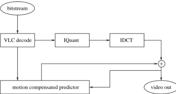
The decoding process is depicted in Figure 2 which is basically the lower part of the encoding process.
First, the incoming bitstream is decoded using variable length decoding. Second, the results are fed into an inverse quantization step and an inverse DCT step. If the blocks were not motion-compensated difference blocks, they can be directly fed to the output of the decoder. If motion vec-tors are decoded, then they are used to fetch data from ref-erence frames, to which the decoded diffref-erence values are
+
motion compensated predictor video out IDCT
VLC decode IQuant bitstream
Figure 2. Diagram of a MPEG decoder imple-mentation.
added. Worth noting is that the MPEG standard is not sym-metric, meaning that the computational requirements for the encoder and the decoder are different. For example, the en-coder has to put lots of effort in calculating motion vectors, while the decoder just uses motion vectors to fetch the right block from memory.
This paper focuses on ways to speed up the motion es-timation part of MPEG encoding, also denoted as motion
vector search. There are several algorithms to compute
which block in the reference frame most closely resembles the current block. At one end of the spectrum is the ex-haustive search [12] which is time-consuming, but produces the best possible result, and at the other end there are sev-eral heuristic-based algorithms, which are much faster at the cost of a possibly less optimal result. Examples of these heuristic-based search algorithms are the Three Step Search [8] and the Two Dimensional Logarithmic search [5, 14]. The assumption made by these algorithms is that the global minimum can be reached by following the steepest descent. If the results are less optimal, this will yield an increase in the number of difference values and larger difference val-ues. This in turn results in larger bandwidth requirements or quality degradation if bandwidth constraints apply, be-cause coarser quantization must be applied.
Irrelevant of the search algorithm to determine the best resemblance, a metric is used which indicates the “close-ness” between compared blocks. The two most com-mon metrics found in different search algorithms are the
mean square error (MSE) and the mean absolute difference
(MAD). The MSE is performed by the following (assuming blocks of 16x16 pixels):
MSE
(x;y;r;s
)= 1 256i
=15 Xi
=0j
=15 Xj
=0 ?A
(x
+i;y
+j
) ?B
((x
+r
)+i;
(y
+s
)+j
) 2 (1)The MAD is performed by
MAD
(x;y;r;s
)= 1 256i
=15 Xi
=0j
=15 Xj
=0A
(x
+i;y
+j
) ?B
((x
+r
)+i;
(y
+s
)+j
) (2)MAD can also be rewritten as
MAD
(x;y;r;s
)=SAD
(x;y;r;s
) 256(3) where SAD is the summation of the absolute differences, that is:
SAD
(x;y;r;s
)=i
=15 Xi
=0j
=15 Xj
=0 jA
(x
+i;y
+j
) ?B
((x
+r
)+i;
(y
+s
)+j
) j (4)In these equations (x,y) is the position of the current block and (r,s) denotes the motion vector, i.e. the displace-ment of the current block (A) relative to the block in the reference frame (B). The
x
andy
in Equations 1 though 4 are multiples of 163for MPEG1 and the values ofr
ands
are determined by the algorithm.Given that the MAD metric, due to its computational simplicity, is used more often, we will not consider the MSE in our discussion. In the section to follow, we introduce a novell approach for the computation of the SAD which leads to the computation of the MAD with a trivial exten-sion.
3. Computing the Sum Absolute Difference
In this section we proceed by investigating the SAD op-eration and propose some possible parallel implementations leading to an instruction proposal for SAD. The general algorithm computing the Sum Absolute Difference of two blocks is depicted in Equation 4. A direct approach in com-putation the SAD consists of the following steps:
Compute (
A
i
?B
i
) for all 16x16 pixels in the twoblocks A and B.
Determine which
A
i
?B
i
are less that zero andpro-duce in that case
B
i
?A
i
as the absolute value, elseproduce
A
i
?B
i
.Perform the accumulate operation to all 16x16
abso-lute values.
3We note that we assume in the remaining of the presentation 16x16 pixel MPEG1 blocks. This assumption is not restrictive as our proposal supports arbitrary block-sizes.
In order to speed up the computation, we perform a mul-tiplicity of operations in a single operation. In the case of the computation of the SAD we want to eliminate the absolute-difference operations. Generally, it is not possi-ble to eliminate these operations, because of the inability to take an absolute operation out of a summation.
X
j
A
i
?B
i
j6=j X(
A
i
?B
i
)j (5)Our solution to this problem is as follows. By determin-ing the smallest of both operands and subtractdetermin-ing it from a constant, it becomes possible to eliminate the absolute oper-ations. This subtraction is a trivial operation, if the constant is chosen correctly.
To achieve our goal, we first briefly describe an unit ca-pable of computing the SAD of 16x1 pels in parallel, where each pel(pixel) is represented in 8 bits (in unsigned binary notation).
Determine the smallest of two operands This is done by inverting one of the operands, and computing the carry-out which would arise from the addition of both operands.
Invert the smallest operand and pass both operands to an adder tree. The smallest operand is inverted, which means that its value changes to2
8
?1?
X
= 255?X
. Both the inverted smallest and the largestvalues are passed to the adder-tree, which corrects for this constant (2
8
?1=255).
The above two steps can be carried out in parallel for 16 pels. The result is 32 8-bit values, on which the following steps are applied.
Addition of a correction term The correction term is added to account for the 2
n
?1’s introduced by theinverting of the smallest value. If the number of pels on which the unit is operating is a power of2, the
cor-rection term is equal to that number, as the sum of the
2
n
adds up to one “simple eliminatable bit”. If thenumber of pels the unit operrates on is not a power of two, we also have to account for the additional2
n
perpel.
Reduce the33rows to2 The resulting32rows passed to
the adder tree and the correction-term is 33 rows, are reduced to2rows by using a counter scheme, see for
example [19, 2, 16].
Reduce the2rows to1(accumulation) In this final step,
a full summation of the two remaining rows is per-formed. The total sum of all constants, which has to be discarded, is the carry out of this addition.
A more thorough explanation of each step follows below, which is using
n
for the number of bits to represent the lu-minance pels andm
instead of16for the number of pels onwhich the unit operates. Note that if
m
is a power of2, wehave a special case which may simplify some computations.
Step 1, Determining the smallest: Both operands
A
andB
are positive numbers in binary representation inn
bits and range from 0to(2n
?1). The result ofjA
?B
jis alsoin unsigned binary representation, and has also the same range. To avoid the absolute operation, we can substitute
j
A
?B
jwithA
?B
orB
?A
, depending whetherA
orB
is the smallest. To determine which one is the smallest, we have to check whether the following inequality is true or false:B > A
(6)B
?A >
0 (7)Generally it is not possible to subtract two positive numbers without the possibility of producing a negative result which can not be represented as an unsigned number. If we sub-tract
A
from its maximum value,P
n
?1i
=02
i
= 2n
?1, theresult is always positive or zero. The result of the subtrac-tion(2
n
?1?A
)isA
, the binary bit by bit inversion ofA
.This can be concluded from the following equation:
A
+A
=n
Xi
=0 2i
=2n
?1 (8)A
= 2n
?1?A
(9)We still have to check the following inequality:
B > A
. We rewrite this inequality to:B > A
(10)?
A
+B >
0 (11)2
n
?1?A
+B >
2n
?1 (12)A
+B >
2n
?1 (13)A
+B
2n
(14)The last step is possible because we are dealing with natural, non-fractional, numbers.
The maximum value of
A
+B
is 2(2n
?1) = 2n
+1
?2. This is a
n
+1bit number. The most-significantbit, with weight2
n
, is computed as the carry-out of then
bit addition. Thus checking whether
A
+B
2n
meanschecking whether the addition of the bit inverted A and the operand B produces a carry out.
Step 2, Inverting the smallest value: To computej
A
?B
jin a single step (which will improve the computation of the SAD) we can compute separately
A
?B
andB
?A
anddetermine which of the two has a negative result. Conse-quently, we could choose (multiplex) between the two re-sults choosing the “positive” value. There are two draw-backs with this approach. One relates to the hardware, the other to delay. To perform the entire operation in parallel we must consider two adders per single operation and pay, in addition to the adder delay, the multiplexer delay. The two problems can be alleviated by doing the following. In-stead of adding the two input values, we convert the smallest input value to2
n
?1?X
=X
, (that is the one’scomple-ment of X). In the remaining discussion, these two values form two rows and they are denoted as a couple.
There are two cases arising from the previous step:
No carry was generated This implies
B
6> A
. Inthis case we should invert
B
toB
. As stated previously, the value ofB
is equal to the posi-tive number2n
?1?B
. This number is againin unsigned binary representation. The value
A
should be propagated unmodified. Their sum equals2n
?1?B
+A
=2n
?1+jA
?B
j.A carry was generated This implies
B > A
. In this case we should invertA
toA
and propagateB
unmodified. Their sum equals2n
?1?A
+B
= 2n
?1+jA
?B
j.Thus in both cases, the
n
+1bit sum of the two valuesis equal to 2
n
?1+jA
?B
j, which is the desired value jA
?B
jplus a constant of 2n
?1. In the next step, thisconstant will be eliminated. It should be noted here, as also indicated in step1, that the inversion of the operands A or B is not known a priori. To determine which operand (
A
orB
) to invert, it is enough to compute the carry out of the operationA
+B
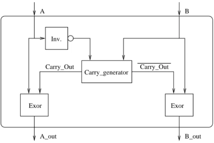
(see step1 for further elaboration).Step 2 takes one level of multiplexers and can be per-formed in the same first cycle. This step produces two n-bit numbers, which are added in step 4. Figure 3 gives a graph-ical representation of the first two steps. We note here that steps 1 and 2 substitute two adders and multiplexing logic of the output of the adders with carry-out-detection logic and multiplexing of operands improving both the hardware and the delay requirements.
Step 3, Adding a correction term: In order to parallelize
the computation of the SAD, the two previous steps are per-formed on
m
couples (that is A,B operands) in parallel. The2
m
rows, the result of step 1 and 2, are positioned into amatrix which is then reduced (summed) using some well known counter-scheme and discussed in steps 4 and 5.
Each of the
m
couples has a sum equal to2n
?1+jA
i
?B
i
j, assumingA
i
andB
i
of lengthn
. Thus the sum of allA B Carry_Out Carry_Out A_out B_out Carry_generator Inv. Exor Exor
Figure 3. Graphical representation of the first two steps in computing the Sum Absolute Dif-ference (SAD).
couples has the value
Sum
=m
(2n
?1)+m
?1 Xi
=0j
A
i
?B
i
j (15)which can be rewritten as:
Sum
=m
2n
?m
+m
?1 Xi
=0j
A
i
?B
i
j (16)Because j
A
i
?B
i
j is always less than 2n
, the sum Pm
?1
i
=0j
A
i
?B
i
j will always be less thanm
2n
. Thedesired sum is therefore always representable in
n
+ dlog
2
(
m
)ebits.For this discussion, we define
q
=dlog
2(
m
)e.In order to eliminate the constant
m
2n
?m
from thesum without subtraction, we have to be able to split the re-sult in two parts. The first part consists of the lower(
q
+n
)bits, and the higher part consists of the most-significant bit, with value2
q
+
n
. We now have to make sure that the sum of the constants equals this most-significant bit, by adding an extra constant. The value of this extra constant is computed at design-time with the following formula:
Extra Constant
=2q
+n
?
m
2n
+m
(17)Note that in the case that
m
is a power of 2, it simply takes is the valuem
. (fill in2q
form
in the above equation)After adding this extra constant, the total sum will be:
Total Sum
=Extra Constant
+Sum
Total Sum
=2q
+n
?m
2n
+m
+ +m
2n
?m
+m
?1 Xi
=0 jA
i
?B
i
jTotal Sum
=2q
+n
+m
?1 Xi
=0 jA
i
?B
i
j (18) Given that2q
+n
is not required to represent the result, it can be discarded producing the needed Final Sum as:
Final Sum
=Total Sum
?2q
+n
Final Sum
=2q
+n
+m
?1 Xi
=0 jA
i
?B
i
j?2q
+n
Final Sum
=m
?1 Xi
=0 jA
i
?B
i
j (19)Step 4, Matrix reduction: In step 4, we reduce the matrix
of2
m
+1rows ofn
bits to 2 rows.This matrix reduction can be done in several ways. We could use for example Lim counters [9], 6-2 counters [16, 13], or a tree of Carry-Save-Adders (CSA)[19, 2]. The Carry-Save-Adder-Tree approach is used in the example in Section 4 and shows that for
m
=16andn
=8, 260 CSA’sin 8 levels can reduce the 33 rows to 2.
Step 5, Final reduction: The last step is the final reduction
of the matrix. This is done using a fast carry-lookahead scheme.
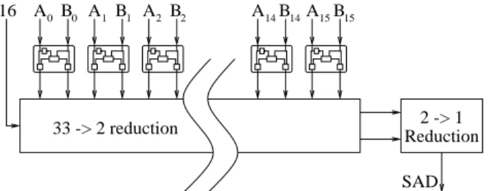
Figure 4 shows a graphical representation of a 16x1 unit, that is a unit operation on 16 couples of elements producing a single output value. The top half shows 16 times steps 1 and 2 in parallel, and steps 4 and 5 are depicted in the bottom half. Step 3 is represented by the addition term at the left (16).
The concept can be expanded to an array capable of com-puting the SAD of 16x16 pel blocks. In this case, the 2 rows going into the 2-to-1 reduction should go into another 32-to-2 reduction unit, together with the 30 rows of the 15 other units. The result of this 32-to-2 reduction is then reduced by a 2-to-1 final adder. This saves both the execution time and the area of 15 2-to-1 reduction units. For a block diagram of this extension see Figure 5
4. A Sample Hardware Implementation
As an example, we describe the implementation of an unit which computes the SAD of two 16x1 blocks, which
33 -> 2 reduction Reduction2 -> 1 SAD
B B A B A B A B
16 A0 0 A1 1 2 2 14 14 15 15
Figure 4. Graphical representation of the SAD computation of a 16x1 block by using 16 of the blocks from Figure 3 in parallel and a multiplier-like tree reduction.
33 -> 2 reduction A B A B A B A B A B 16 33 -> 2 reduction A B A B A B A B A B 16 33 -> 2 reduction A B A B A B A B A B 16 33 -> 2 reduction A B A B A B A B A B 16 A B A B A B A B A B 16 33 -> 2 reduction Reduction 32 -> 2 Reduction 2 -> 1 SAD
Figure 5. A 16x16 pel SAD computation unit. Note that each block is assumed to take one cycle, thereby making the total number of cy-cles for this unit equal to 4.
can be either a row or a column of a 16x16 macroblock. We assume 8 bit values which is common in MPEG.
Step 1, Determining the smallest: We need 16 parallel
blocks to perform step 1. In each of these blocks, we first need to compute the
C
out
of the n bit additionA
+B
. Thisis formed by:
C
out
=G
7 0 +P
7 0C
in
(20)In Equation 20, P stands for Propagate and G for Gener-ate. Because
C
in
is always zero in this case, we can ignoreP
70. The remaining term to compute is
G
70. This can be
computed in 4 stages using 2x2 And-Or-Invert as the most complex gate as follows:
Stage 1
G
0 0 =a
0b
0 (21)::::
G
7 7 =a
7b
7 (22)P
1 1 =a
1 +b
1 (23)::::
P
7 7 =a
7 +b
7 (24) Stage 2G
7 6 =G
7 7 +P
7 7G
6 6 (25)G
5 4 =G
5 5 +P
5 5G
4 4 (26)G
3 2 =G
3 3 +P
3 3G
2 2 (27)G
1 0 =G
1 1 +P
1 1G
0 0 (28)P
7 6 =P
7 7P
6 6 (29)P
5 4 =P
5 5P
4 4 (30)P
3 2 =P
3 3P
2 2 (31) Stage 3G
7 4 =G
7 6 +P
7 6G
5 4 (32)G
3 0 =G
3 2 +P
3 2G
1 0 (33)P
7 4 =P
7 6P
5 4 (34) Stage 4G
7 0 =G
7 4 +P
7 4G
3 0 (35)It might be convenient to compute
G
70in the same stage.
G
7 0 =G
7 4 +P
7 4G
3 0 (36)G
7 0 =G
7 4P
7 4G
3 0 (37)Depending on the chosen technology, it might be possi-ble to skip the first stage, and to merge it with the second stage.
Step 2, Inverting the smallest: In the second step, we have
to invert the smallest of A and B. Again, this needs to be done for 16 input-pairs. In terms of hardware, this operation is merged with the operation in step 1 and performed as follows. Stage 5 8
i
2f0::
7g;
a
i;out
=G
7 0a
i
+G
7 0a
i
(38)b
i;out
=G
7 0b
i
+G
7 0b
i
(39)These 5 stages of step 1 and 2 can be executed in the first cycle.
Step 3, Placing the correction term: In step 3 we place
a correction-term to the terms to be added. Therefore, the number of rows to add up in step 4 becomes162+1=33.
The correction term has a predetermined value, computed at design time with Equation 17. This step does not take any execution time.
Step 4, Reducing the matrix: In step 4, we perform the
matrix reduction. For a 33-to-2 reduction, a total of 260 Carry Save Adders in 8 levels suffices.
Step 5, Final addition: Step 5 is the final 2-to-1 addition.
This is done using a carry-lookahead scheme.
The last two steps each take one cycle, making the total number of cycles needed equal to 3.
5. Conclusions and future work
In this paper, we proposed a hardware unit capable of computing the SAD instruction. In particular, we consid-ered two example implementations assuming 16x1 and a 16x16 pel blocks. The proposed sample implementation schemes compute the SAD in 3 or 4 cycles respectively.
We are able to perform the SAD in a small amount of cycles, because of the following two reasons:
we have substituted complex operations (i.e subtract
and absolute operation) with two simple operations (determining and inverting the smallest).
we have substituted the subtractions and the
accumu-lation operation by one multi-operand addition. This speed advantage is especially beneficial for data-dependent algorithms, such as the three-step search algo-rithm. These algorithms need the SAD of the blocks in their first step to compute the addresses of the blocks in the sec-ond step.
There are however two problems which must be ad-dressed in future research.
Bandwidth The bandwidth required to feed our unit is
rather high. This means that some sort of on-chip cache is needed to store the reference frames.
Data-alignment The current-frames are always positioned
on 16 byte boundaries, while most reference frames will not be aligned. This means that special hardware is needed to align the data.
References
[1] N. Ahmed, T. Natarajan, and K. Rao. Discrete cosine trans-form. IEEE Transactions on Computers, pages 90–93, jan 1974.
[2] L. Dadda. Some schemes for parallel multipliers. Alta
Fre-quenza, 34:349–356, May 1965.
[3] B. Furht, J. Greenberg, and R. Westwater. Motion
Estima-tion Algorithms for Video Compression. Kluwer Academic
Publishers, 1997.
[4] D. L. Gall. Mpeg: A video compression standard for multi-media applications. Communications of the ACM, 34(4):46– 58, April 1991.
[5] J. R. Jain and A. K. Jain. Displacement measurement and its applications in interframe image coding. IEEE
Trans-actions on Communications, COM-29(12):1799–1808,
De-cember 1981.
[6] S. Kappagantula and K. Rao. Motion compensated predic-tive coding. In Proc. Int. Tech. Symp. SPIE, San Diego, CA, August 1983.
[7] H. Kitjima. A symmetrric cosine transform. IEEE
Transac-tions on Computers, c-29(4):317–323, april 1980.
[8] T. Koga, K. Linuma, A. Hirano, Y.Iijima, and T. Ishiguro. Motion-compensated interframe coding for video confer-encing. In NTC 81 Proc., pages G5.3.1–5, New Orleans, LA, December 1981.
[9] R. Lim. High-speed multiplication and multiple summand addition. In Proc. IEEE 4thSymp. Com. Arithmetic, pages 149–153, October 1978.
[10] J. L. Mitchell, W. B. Pennebaker, C. E. Fogg, and D. J. LeGall. MPEG Video Compression Standard. Digital Mul-timedia Standard Series. Chapman and Hall, 1996.
[11] R. Montoye, E. Hokenek, and S. Runyon. Design of the IBM RISC System/6000 floating-point execution unit. IBM
Journal of Research and Development, 34(1):59–70,
Jan-uary 1990.
[12] A. N. Netravali and B. G. Haskell. Digital Pictures;
Rep-resentation, Compression, and Standards. Plenum Press,
1994.
[13] P. Song and G. De Michelli. Circuits and architecture trade-offs for high-speed multiplication. IEEE Journal of
Solid-State Circuits, SC-26(9):1184–1198, 1991.
[14] R. Srinivasan and K. Rao. Predictive coding based on motion estimation. IEEE Transactions on Communicatios, COM-33:1011–1014, September 1985.
[15] B. Tseng and W. Miller. On computing the discrete cosine transform. IEEE Transactions on Computers, c-27(10):966– 968, Oct 1978.
[16] S. Vassiliadis, J. Hoekstra, and H.-T. Chiu. Array multipli-cation scheme using (p,2) counters and pre-addition.
Elec-tronics Letters, 31(8):619–620, April 1995.
[17] S. Vassiliadis, E. M. Schwarz, and D. J. Hanrahan. A general proof of overlapped multiple-bit scanning multiplications.
IEEE Transactions on Computers, 38(2):172–183, February
1989.
[18] S. Vassiliadis, E. M. Schwarz, and B. M. Sung. Hard-wired multipliers with encoded partial products. IEEE
Transac-tions on Computers, 40(11):1181–1197, November 1991.
[19] C. Wallace. A suggestion for parallel multipliers. IEEE