Object Recognition and Obstacle Avoidance Robot
Karthi Balasubramanian, Arunkumar R, Jinu Jayachandran, Vishnu Jayapal, Bibin A Chundatt, Joshua D Freeman
Department of Electronics and Communication Engineering, Amrita School of Engineering Amrita Vishwavidyapeetham, India.
Abstract—Design highlights of a ‘Three-wheeled Autonomous Navigational Robot’ are presented in this paper. An efficient modular architecture is proposed for ease of adding various modules to the robot. Obstacle detection, pattern recognition and obstacle avoidance are the key aspects of the design. The robot has intelligence built into it that enables it to recognize and pick up balls of a particular colour and ignore other objects in its path. A single board computer mounted on the robot acts as the central controller. It communicates with ultrasonic sensors and motors through multiple microcontrollers and controls the entire motion of the unit. As part of the robot design, a modified H-bridge circuit for driving DC motors efficiently is proposed in this paper.
Index Terms—Modular Robot Architecture, Obstacle Detec-tion, SONAR, Object RecogniDetec-tion, Hough Transform, Modified H-Bridge Circuit.
I. INTRODUCTION
An autonomous robot is one that has ’Artificial Intelligence’ built into it. The paper presents the design of a mobile robot that navigates on its own, avoids obstacles and detects and picks up balls of a particular colour. If needed, the robot can also be operated manually. A Mini-ITX motherboard is mounted on the robot to connect wirelessly to the remote computer used for manual operation.
There has been a lot of work done in designing robots with image processing capabilities. Hrabek and Honzik [1] have designed a robot control mechanism based on a single chip microcontroller and specialized DC motors. Algorithms for image processing and object recognition have also been discussed in the same. Liu and Zhang [2] have presented methods for modular robot design. But an in-depth design analysis covering different aspects of robot design is missing in all these works. This paper aims at presenting an efficient architecture for a robot design.
The design can be broadly divided into three sections -Mobility, Obstacle Avoidance and Computer Vision. Mobility deals with the design of the robot platform and the robotic arm, while obstacle avoidance involves interfacing ultrasonic range finders to detect objects and computer vision deals with object recognition.
The top level system architecture and the various module descriptions are discussed in section II. Some simulation results are also presented here. The paper then concludes in section III.
II. ROBOTARCHITECTURE
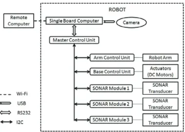
The block diagram of the architecture is shown in Fig. 1. A modular approach is followed where the system is divided
Fig. 1. System Level Block Diagram
into separate modules, each of which is controlled by seperate microcontroller units that act as slaves. All of the slaves are in-turn controlled by a master unit that receives its instructions from the on-board ’Mini-ITX VIA’ computer. The master unit connects to the onboard computer through the RS232 port and to the slave units through the I2C protocol [3]. The master acts as an intermediate channel between the on-board computer and the different slave modules. Whenever the onboard computer wants to communicate with a particular module, it sends a 7 byte frame to the master unit. The first byte denotes the slave address and the interpretation of the rest of the six bytes depends on the module to which it needs to communicate with. (For Example: the six bytes for the base unit carry information about the DC motor direction, the value for the PWM signals and the distance to be moved). The Master places this 7 byte data frame on the I2C bus. Only the slave whose address matches with the first byte of this frame accepts and acknowledges the request.
The design consists of an on-board computer with a we-bcam, one master microcontroller and three slave modules, namely: Arm, Base and SONAR. The modular design ap-proach ensures that new slave modules can be added with no change in the existing system, thus enabling a plug and play feature.
A Java program running on the on-board computer acts as the central controller for the functioning of the unit. It initiates the motion of the robot base and at the same
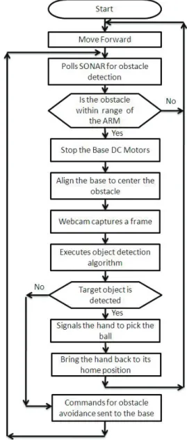
time, constantly sends messages to the SONAR module. The ultrasonic sensors of the SONAR module respond back with an acknowledgement whenever an obstacle is detected. The SONAR module also calculates the distance of the object and sends it to the master. When the distance is within the reach of the robot arm, a message is sent by the master to the base unit to apply the brakes and stop the unit. With the help of three sonar sensors, the base is aligned to be exactly in front of the object. This ensures proper focusing of the webcam to capture the image of the obstacle accurately. A frame is then captured and the image is analyzed to identify the shape and the colour of the object. If it matches the specification of our object then the arm unit is activated to pick up the ball, else the robot moves around the obstacle and continues on its path. A. Mobility
1) Robot Platform: The Robot platform consists of a base with wheels and motors attached to it. The main criteria for selecting a wheel configuration are stability and the ability to turn without displacement, i.e. turning with zero radius. Static stability requires a minimum of three wheels with the additional requirement that the center of gravity must be inside the triangle formed by the three wheels [4]. The current design uses two standard wheels for rear drive and a swivel wheel in the front.
Fig. 2. Zero radius turn by three wheel configuration
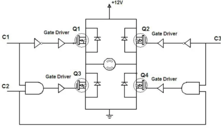
Fig. 3. Modified H-Bridge circuit
The main criteria for selecting motors for driving the robot are light weight and good speed-torque characteristics.
A geared DC motor taken from the power window of an automobile was chosen for the design. The motor is driven by a modified H-bridge circuit as shown in Fig. 3. With a standard H-Bridge circuit, there is a possibility of inadvertantly turning on the mosfet pairs Q1, Q3 or Q2, Q4, thus shorting power and ground. The modified design helps in preventing this undesirable situation by ensuring that the inputs to the gates of the respective mosfet pairs are always complementary in nature. Due to different gate delays of AND and NOT gates, a short circuit might occur for a small period of time while changing the directions of the motors. This problem can be resolved by pulling the speed control signal (c2) low while changing the directions using c1 and c3.
Another problem that arose was due to the heavy load current of the motors. A high value of back EMF was being generated that burnt out the mosfets. Hence, in addition to the already built in diodes in the power mosfets, an extra diode was connected between the source and the drain of all mosfets to reduce the effect of the back EMF. For the motor to be driven by the 12 V supply, transistors Q1 and Q2 need to pass the 12 V supply to the source terminals. Hence Driver IC MAX620 is used to ensure that the input to the gate is at least one threshold voltage above that of the supply in order to enable the source to get charged all the way up to the supply voltage.
Since DC motors do not have in-built feedback mechanisms, precision control is obtained by using an optical feedback mechanism as shown in Fig. 4.
Fig. 4. Optical Feedback Circuitry
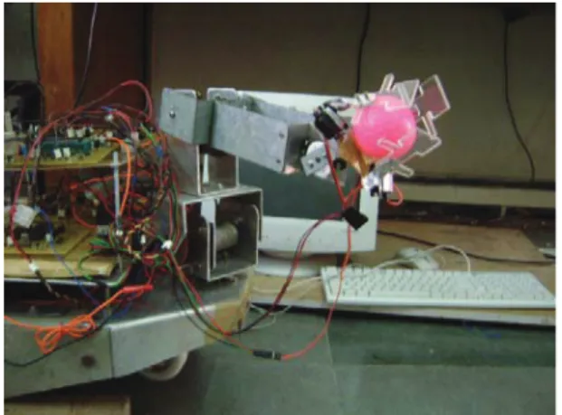
2) Robot Arm: The robot arm consists of six servo motors and one DC motor providing 5 degrees of freedom. There are three servo motors in the fingers with which the robot can grab a ball comfortably. Two servos are used for the palm and the elbow and one servo is used for rotating the arm. A high torque geared-DC motor with optical feedback is used for the shoulder part of the arm. Fig. 5 shows the prototype design of the arm.
The control signal of the servo motors essentially consists of a Pulse Width Modulated (PWM) signal with a time period of 20ms. When the duty cycle of the signal is varied from 5% to 10%, the shaft of the motor turns from 0 to 180 degrees as shown in Fig. 6.
A PIC18F4431 microcontroller with four PWM generators is used to generate the PWM signals. Three microservos are used to control the fingers of the robot. Since we need to move all the three fingers simultaneously for comfortable grabbing of the ball, all the three microservos are connected to the same PWM signal. The other three PWM signals are connected to
Fig. 5. Robot Arm Prototype
Fig. 6. Servo Control Signal
the servo motors at the joints of the robot arm providing the necessary degrees of freedom.
B. Obstacle Detection and Avoidance using SONAR sensors A SONAR,Sound Navigation and Ranging, unit consists of an ultrasonic oscillator and a receiver. The oscillator pro-duces sound waves at a particular frequency. When these sound waves encounter obstacles, they reflect back as echos that are received by the receiver. The output of the sonar receiver is a distorted wave having a 10-20 mV peak to peak voltage. The received voltage varies proportionally to the strength of the signal. By calculating the time taken by the sound waves to reach the receiver after they have been transmitted, the distance of the object from the transmitter can be calculated accurately [5].
1) Distance Calculation Using PIC16F72 microcontroller: A square wave of 40Khz is generated using the microcon-troller and is given as input to the transmitter module. The ultrasonic oscillator of the transmitter vibrates and produces sound waves of40Khz. After transmitting for300usthe input to the transmitter from the microcontroller is suspended. This is done to prevent any direct effect on the receiver, since the receiver and transmitter are placed close to each other. As soon as the 40Khz signal is detected by the receiver, the signal from the output of the receiver is amplified and fed into the external interrupt pin of the microcontroller. By measuring the time between the transmission and reception of the sound waves, the distance of the object is calculated.
2) Signal Analyzer Circuit:As seen in the previous section, the PIC16F72 microcontroller detects the echo through an external interrupt from the receiver. For the microcontroller to recognize the interrupt, it should have a swing of 0V to 5V. To be able to analyze the signal from the sonar, a signal analyzer circuit needs to be designed accordingly.
The sonar signal analyzer circuit consists of three parts 1) Signal amplification circuit
2) Signal detection circuit 3) Signal comparator circuit.
Signal Amplification Circuit
The output from the receiver is amplified using a Quad Comparator (LM324) in two stages with gains of 40 dB and 20 dB. As the microcontroller needs a swing from 0V-5V, the negative terminal of the amplifier is connected to ground and is given a power supply of 9V. The amplifiers are biased about the quiescent point of 4.5V using a voltage divider circuit from the power supply. Therefore both the negative and positive sides of the alternating signal are amplified equally.
Signal Detection Circuit
The amplitude of the received signal varies inversely with the distance of the object. The sonar signal detection circuit shown in Fig 7 uses the same principle as that of an AM en-velope detector. Since high frequency signals are encountered, Schottkey barrier diodes (1N5819) are used for the design of the same.
Fig. 7. Sonar Detection Circuit
Signal Comparator Circuit
The microcontroller identifies the presence of an obstacle by a voltage change of 5V to 0V or vice versa on the external interrupt pin. A LM324 was used to implement the required comparator circuit.
C. Machine-Vision
The aim of the machine-vision component of the robot is to recognize if the detected object is a ball of a particular colour. Object recognition is acheived by using a Hough transform for detecting circles [6]. Initially the algorithm was tested using Matlab simulation and later coded in Java to be run on the on-board computer. Fig. 8 and Fig. 9 show the Matlab and Java simulation results respectively.
Fig. 8. Matlab simulation result of detection of a yellow coloured ball
Fig. 9. Java simulation result of detection of a yellow coloured ball. (Simulation was repeated for different coloured balls)
Algorithm
1) Image Creation
The webcam is activated and a frame is grabbed and converted to an image and saved in the PC.
2) De-noising and Size Reduction
The frame grabbed from the web-cam is converted to an image and stored in the PC. The image is converted to a one dimensional array and the RGB values of each pixel is determined. To reduce the effect of noise, averaging followed by sub-sampling of the image is performed. This is achieved by replacing the centre pixel by the average of the eight pixels surrounding it [7]. Since the size is reduced to one eighth of the original image, the processing time is also significantly reduced.
3) Edge detection
The reduced size image is converted to gray scale and the ‘edge’ function using a Sobel filter is applied to it [8]. The output of the ‘edge’ function is a binary image of the same size as the inputed image with 1’s where the function finds edges and 0’s elsewhere.
4) Hough Transform
A circle detection function using a Hough transform is then applied on this binary image to detect circles. 5) Isolation of a particular coloured ball
In this step, a particular coloured ball is isolated using an averaging method. The values of the pixels inside the detected circles are averaged and are compared with values of a specific colour in a test environment with the same illumination conditions.
The complete process flow diagram is shown in Fig. 10.
III. CONCLUSION
The obstactle detection and avoidance robot has been effi-ciently designed and implemented using a modular architec-ture style. The Java program running on the on-board computer communicates with the master microcontroller through the RS-232 port and controls the entire process. The robot was able to successfully spot and identify balls of various colours and selectively pick them up. A modified H-bridge circuit has been designed for efficiently driving the DC motors of the base unit. A Hough transform algorithm has been successfully used for object detection. The algorithm execution in Matlab took 4 minutes while the real-time operation in Java took only 1 sec.
ACKNOWLEDGMENT
The authors would like to thank the Amrita School of Engineering for providing laboratory facilities (http://www.amritapuri.amrita.edu/robotics), Amrita Research Labs (http://arl.amrita.edu) for providing technical assistance and also Mr. Manickavelu Balasubramanian (former Design Engineer, Intel corp.) for partially funding our research initiative.
REFERENCES
[1] J. Hrabek and B. Honzik, “Mobile robots playing soccer,” inProceedings of 7th International Workshop on Advanced Motion Control, July 2002, pp. 510–513.
[2] Z. M. Liu Xuan and L. Wei, “Methods of modular robot design,” in Pro-ceedings of Second International Symposium on Intelligent Information and Technology Application, Dec 2008, pp. 663–668.
[3] Philips Semiconductors, I2C Bus Specification.
[4] R. Siegwart and I. R. Nourbakhsh,Introduction to Autonomous Mobile Robots, ser. Intelligent Robotics and Autonomous Agents. MIT Press, 2004.
[5] K. V. A. Tsalatsanis and N. Tsourveloudis, “Mobile robot navigation using sonar and range measurements from uncalibrated cameras,”Journal of Intelligent and Robotic Systems, vol. 48, pp. 253–284, Feb 2007. [6] W. H. Dimitrios Loannou and A. Laine, “Comparative study of hough
transform methods for circle finding,” Journal of Image and Vision Computing, vol. 8, pp. 71–77, Jan 1990.
[7] N. Kehtarnavaz and M. Gamadia,Real-Time Image and Video Processing (From Research to Reality). Morgan and Claypool Publishers, 2006. [8] R. C. Gonzalez and R. E. Woods, Digital image Processing. Pearson