BU CS TR97-020. To appear in IEEE Conf. on Computer Vision and Pattern Recognition, Santa Barbara, CA, 1998.
Head Tracking via Robust Registration in Texture Map Images
Marco La Cascia and John Isidoro and Stan Sclaroff
Computer Science Department
Boston University
Boston, MA 02215
Abstract
A novel method for 3D head tracking in the presence of large head rotations and facial expression changes is described. Tracking is formulated in terms of color im-age registration in the texture map of a 3D surface model. Model appearance is recursively updated via image mo-saicking in the texture map as the head orientation varies. The resulting dynamic texture map provides a stabilized view of the face that can be used as input to many exist-ing 2D techniques for face recognition, facial expressions analysis, lip reading, and eye tracking. Parameters are es-timated via a robust minimization procedure; this provides robustness to occlusions, wrinkles, shadows, and specular highlights. The system was tested on a variety of sequences taken with low quality, uncalibrated video cameras. Exper-imental results are reported.
1
Introduction
A wide range of machine vision methods for tracking and recognizing faces, facial expressions, lip motion, and eye movements have appeared in the literature. Potential applications are as diverse and numerous as the algorithms proposed: human/machine interfaces, video compression, video database search, surveillance, etc. One unifying as-pect of these applications is that they require robustness to significant head motion, change in orientation, or scale. Unrestricted head motion is critical if these systems are to be non-intrusive and general.
1.1 Related Work
Several techniques have been proposed for free head motion and face tracking. Some of these techniques focus on 2D tracking (e.g., [5, 8, 10, 14, 19, 20]), while others focus on 3D tracking or stabilization.
Some methods for recovering 3D head parameters are based on tracking of salient points, features, or 2D image patches. The outputs of these 2D trackers can be processed by an extended Kalman filter to recover 3D structure, focal length and facial pose [1]. In [12], a statistically-based 3D head model (eigen-head) is used to further constrain the estimated 3D structure. Another point-based technique for 3D tracking is based on the tracking of five salient points on the face to estimate the head orientation with respect to the camera plane[11].
Others use optic flow coupled to a 3D surface model. In [2], rigid body motion parameters of an ellipsoid model are
estimated from a flow field using a standard minimization algorithm. In other approaches [6] flow is used to constrain the motion of an anatomically-motivated face model and integrated with edge forces to improve the results. In [13], a render-feedback loop was used to guide tracking for an image coding application.
Still others employ more complex physically-based models for the face that include both skin and muscle dy-namics for facial motion. In [18], deformable contour models were used to track the non-rigid facial motion while estimating muscle actuator controls. In [7], a control theo-retic approach was employed, based on normalized corre-lation between the incoming data and templates.
Finally, global head motion can be tracked using a plane under perspective projection [4]. Recovered global planar motion is used to stabilize incoming images. Facial ex-pression recognition is accomplished by tracking deform-ing image patches in the stabilized images.
Most of the above mentioned techniques are not able to track the face in presence of large rotations and some re-quire accurate initial fit of the model to the data. While a planar approximation addresses these problems somewhat, flattening the face introduces distortion in the stabilized image and cannot model self occlusion effects.
1.2 New Approach
In this paper, we propose an algorithm for 3D head tracking that extends the range of head motion allowed in the planar model. Our system uses a texture mapped 3D surface model for the head. During tracking, each input video image is projected into the surface texture map of the model. Model parameters are updated via robust image registration in texture map space. The output of the sys-tem is the 3D head parameters and a 2D dynamic texture map image. The dynamic texture image provides a stabi-lized view of the face that can be used for facial expression recognition, lip reading, and other applications requiring that the position of the head is frontal and almost static.
The system has the advantages of a planar face tracker (reasonable simplicity and robustness to initial positioning) but not the disadvantages (difficulty in tracking large rota-tions). The main differences are that a.) self occlusion can be managed and b.) better tracking of the face can be achieved through the use of a texture map mosaic acquired via view integration as the head moves.
2
Basic Idea
Our technique is based directly on the incoming image stream; no optical flow estimation is required. The ba-sic idea consists of using a texture mapped surface model to approximate the head, accounting in this way for self-occlusions and to approximate head shape. We then use image registration to fit the model with the incoming data. To explain how our technique works, we will assume that the head is exactly a cylinder with a360
o
-wide image, or more precisely a movie due to facial expression changes, texture mapped on its surface. Obviously only a180
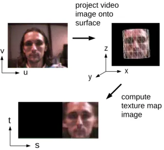
o -wide slice of this texture is visible in each frame. If we know the initial position of the cylinder we can use the incoming image to compute the texture map for the currently visible portion, as shown in Fig. 1. The transformation to project part of the incoming frame in the corresponding cylindrical surface depends in fact only on the 3D parameters of the cylinder and on the camera model.
u v x z y
s
t
project video image onto surface compute texture map imageFigure 1:Mapping from image plane to texture map.
As a new frame is acquired it is possible to find a set of cylinder parameters such that the texture extracted from the incoming frame best matches the reference texture. In other words, the 3D head parameters are recovered by performing image registration in the model's texture map. Due to the rotations of the head the visible part of the tex-ture can be shifted respect to the reference textex-ture, in the registration procedure we should then consider only the intersection of the two textures. A resulting tracking se-quence is shown in Fig. 2.
The registration parameters determine the projection of input video onto the surface of the object. Taken as a se-quence, the project video images comprise a dynamic tex-ture map, as shown in Fig. 3. This map provides a sta-bilized view of the face that is independent of the current orientation, position and scale of the surface model.
Figure 2:Example input video frames and head tracking.
Figure 3:Recovered dynamic texture map images. Note that the video image is mapped into only that portion of the texture map that corresponds with the visible portion of the model. The rest of the texture map is set to zero (black).
At this point the tracking capabilities of this system are only slightly better than that of a planar approach, because a cylinder is a better approximation of a face respect to a plane. The key to allowing for large rotation tracking con-sists of building a mosaicked reference texture over a num-ber of frames, as the head moves. In this way, assuming that there are no huge interframe rotations along the verti-cal axis, we always have enough information to keep the registration procedure working. The resulting mosaic can also be used as input to face recognition.
In practice, heads are not cylindrical objects, so we should account for this modeling error. Moreover, changes in lighting (shadows and highlights) can have a relevant ef-fect and must be corrected in some way. In the rest of the paper, a detailed description of the formulation and imple-mentation will be given. Experimental evaluation of the system will also be described.
3
Formulation
The general formulation for a 3D texture mapped sur-face model will now be developed. Figure 1 shows the var-ious coordinate systems employed in this paper: (x;y;z) is the 3D object-centered coordinate system,(u;v)is the
image plane coordinate system,(s;t)is the surface's para-metric coordinate system. The latter coordinate system (s;t) will be also referred to as the texture plane as this is the texture map of the model. The(u;v)image coordi-nate system is defined over the range[;1;1][;1;1]and the texture plane(s;t)is defined over the unit square.
The mapping between(s;t)and(u;v)can be expressed as follows. First, assume a parametric surface equation:
(x;y;z;1)=x(s;t); (1) where 3D surface points are in homogeneous coordinates.
For greater generality, a displacement function can be added to the parametric surface equation:
x (s;t)=x(s;t)+n(s;t)d(s;t); (2) allowing displacement along the unit surface normaln, as modulated by a scalar displacement functiond(s;t). For an even more general model, a vector displacement field can be applied to the surface. Displacement functions will be included in a future version of our system.
The resulting surface can then be translated, rotated, and scaled via the standard44homogeneous transform:
M=TR x R y R z S; (3)
whereTis the translation matrix,Sis the scaling matrix, andR
x, R
y, R
zare the Euler angle rotation matrices. Given a location (s;t) in the parameter space of the model, a point's location in the image plane is obtained via a projective transform:
u 0 v 0 w 0 T =PM x(s;t); (4) where(u;v)=(u 0 =w 0 ;v 0 =w 0
), andPis a camera projec-tion matrix: P= 2 4 1 0 0 0 0 1 0 0 0 0 1 f 1 3 5 : (5)
The projection matrix depends on the focal lengthf, which in our system is assumed to be known.
3.1 Image Warps
Tracking is achieved via image registration in the tex-ture map plane(s;t). However, the input video sequence is given in the image plane(u;v). Image warping func-tions are therefore needed to define the forward and inverse mappings between the two coordinate spaces.
Using Eqs. 4 and 5, a forward warping function is de-fined that takes the texture mapI(s;t)into the video image I 0 (u;v): I 0 =(I;p); (6)
wherepis a vector containing the parameters for the model transformation matrixM, and the focal lengthf.
Forward warpings can be achieved by applying the tex-ture image to the surface and then generating a raster graphics rendering of a texture mapped model. This ap-proach has the added advantage of visibility testing; only the forward-facing portion of the model will be rendered.
In practice, the surface is approximated by a 3D triangle mesh. The warped image is then computed via Z-buffered rendering of the triangular mesh with bilinear resampling of the texture map. By defining image warping in this way, it is possible to harness hardware accelerated triangle tex-ture mapping capabilities becoming prevalent in mid-end workstations, PC's, and computer game consoles.
An inverse function is also needed to warp images from the input video into the texture plane:
I= ;1
(I 0
;p): (7)
If the underlying 3D surface model is convex, then this inverse warping can be obtained via raster graphics meth-ods. For each visible triangle of the cylinder we compute the corresponding coordinates of the vertices in the image plane using transform Eq. 5. Once the image plane coordi-nates of the vertices of a triangle are known, we can sim-ply map this portion of the video frame to the texture map (s;t) using the graphics pipeline's bilinear interpolation. Repeating this step for each visible triangle, the resulting warped image can be obtained. Note that the video image is mapped into only that portion of the(s;t)plane that cor-responds with the visible portion of the model. The rest of the image is set to zero.
3.2 Confidence Maps
As we warp video into the texture plane, not all pix-els have equal confidence. This is due to nonuniform den-sity of pixels as they are mapped between(u;v)and(s;t) space. As the input image is inverse projected, all visible triangles have the same size in the(s;t)plane. However, in the(u;v)image plane, the projections of the triangles have different sizes due to the different orientations of the triangles, and due to perspective projection. An approxi-mate measure of the confidence can be derived in terms of the ratio of a triangle's area in video image(u;v)over the triangle's area in the texture map(s;t).
In practice, the confidence map is generated using a standard triangular area fill algorithm. The map is first ini-tialized to zero. Then each visible triangle is rendered into the map with a fill value corresponding to the confidence level. This approach allows the use of standard graphics hardware to accomplish the task.
The confidence map can be used to gain a more prin-cipled formulation of facial analysis algorithms applied in the stabilized texture map image. In essence, the confi-dence map quantifies the reliability of different portions of the face image. The nonuniformity of samples can also bias the analysis, unless a robust weighted error residual
scheme is employed. As will be seen in the next sec-tion, the resulting confidence map also enables the use of weighted error residuals in the tracking procedure.
4
Registration and Tracking
The goal of our system is nonrigid shape tracking. To achieve this, the system recovers the model parametersp that warp the video image I
0
(u;v)into alignment with a given reference textureI
0
(s;t). If we assume that image warps at different times are independent of each other, then M-estimation of image motion can be solved via registra-tion of sequential image pairs.
We formulate the solution to this two image registration problem as minimizing the error over all the pixels within the region of interest:
E(p) = 1 n n X i=1 (e i ;) (8) e i = kI 0 (s i ;t i );I(s i ;t i )k; (9) where is a scale parameter that is determined based on expected image noise, andis is the Lorentzian error norm (e i ;) = log(1+e 2 i =(2 2
)). Using the Lorentzian is equivalent to the incorporation of an analog outlier process in our objective function [3]. The provides in better robust-ness to specular highlights and occlusions. For efficiency, thelogfunction can be implemented via table look-up.
As previously noted, the reference and the transformed video images have an associated confidence map. It makes sense then to minimize a weighted cost function:
E(p)= 1 k n X i=1 w(s i ;t i ;p)w 0 (s i ;t i )(e i ;) (10) where k = P i w(s i ;t i ;p)w 0 (s i ;t i ) is a normalization term, w(s i ;t i ;p) andw 0 (s i ;t i
)are the confidence maps associated with the transformed video and reference tex-tures, respectively.
To solve the registration problem, we minimize Eq. 10. Three nonlinear minimization approaches have been tested in our system: Powell line minimization [15], Marquardt-Levenberg [15, 17], and the difference decomposition [9]. Powell and Marquardt-Levenberg procedures were taken directly from [15], and will not be repeated here. The dif-ference decomposition approach had to be adapted, and will now be described.
4.1 Difference Decomposition
In the difference decomposition approach, we consider anrgbimage in the(s;t)plane as a long vector, defining a difference basis set in the following way:
b k =I 0 ; ;1 ((I 0 ;n k );p 0 ); (11) wherep
0are the initial parameters for the model, and n
k is the parameter displacement vector for thek
th
basis im-age. In other words, difference basis images are obtained
by slightly changing one of the transformation parameters, leaving the other parameters unaltered, to obtain a differ-ence template for that parameter. Each resultant differdiffer-ence image becomes a column in a difference decomposition ba-sis matrixBas described in [16].
In practice, four basis vectors per model parameter are sufficient. For the k
th
parameter, these four basis im-ages correspond with the difference patterns that result by changing that parameter by
kand 2
k. Values of the
k are determined such that all the difference images have the same energy. Givenb
0, a simple bisection technique can be used to solve for
kwith respect to the equation: kb
k k;kb
0
k=0: (12)
Once the difference decomposition basis has been com-puted, tracking can start. Assumepis the parameter vector at the previous time step, andI
0
(u;v)is the incoming im-age. We then compute the difference imageDbetween the transformed video image and the reference texture map:
D=I 0 ; ;1 (I 0 ;p) (13)
The difference image can now be approximated in terms of a weighted combination of the difference decomposi-tion's basis vectors:
WDWBq; (14)
whereq is a vector of basis coefficients, and W is di-agonal confidence weighting matrix. Each didi-agonal ele-ment inWcorresponds with the product of confidence at each pixel in the transformed video and reference texture: w(s i ;t i ;p)w 0 (s i ;t i ).
The maximum likelihood estimate of q can be com-puted via weighted least squares:
q=(B T W T WB) ;1 B T W T WD (15)
The change in the model parameters is then obtained via matrix multiplication:
p=Nq; (16)
whereNhas columns formed by the parameter displace-ment vectorsn
kused in generating the difference basis. This procedure can be repeated iteratively for each frame, until the percentage error passes beneath a thresh-old, or the maximum number of iterations is reached. Ex-perimentally we found that two or three iterations are gen-erally sufficient to reach a much better point in the param-eter space, improving tracking precision and stability.
For added stability, the difference decomposition ba-sis is updated periodically during tracking. This update is needed due to possible facial expression changes and due to new parts of head rotating into view. In our implemen-tation, this update is done every ten frames.
5
Texture Map Mosaics
As described above, at each frame we estimate: 1.) the 3D head parameters, 2.) the input video image stabilized in the texture plane, and 3.) the confidence map. We would like to integrate this information over a collection of frames to obtain a mosaicked texture map and confidence map.
Mosaicking is accomplished via a recursive procedure. For each new frame, we integrate the incoming texture with the mosaic by replacing pixels for which the incoming im-age has higher confidence. The same procedure is used to update the confidence map. Computing the mosaicked tex-ture using a weighted combination of the new data and old data with a time decay factor is under investigation.
Registration with the mosaic can yield better tracking, since it provides a wider, integrated texture of the head. The advantage of using the mosaicked texture is that in general the intersection between the mosaic texture map and the projected video stream is in general180
o
-wide, so we can use all of our incoming information. The resulting mosaic could be useful in 2D face recognition applications.
6
Nonrigid Tracking in the Texture Map
Given the stabilized view provided in the dynamic tex-ture map, we can track nonrigid deformation of the face. Our approach takes its inspiration from [4]: nonrigid fa-cial motions are modeled using local parametric models of image motion in the texture map. Our approach confines nonrigid motion to lie on a curved surface, rather than in a flat plane. This enables view independent modeling of nonrigid motion of the face.
A parametric warping function controls local nonrigid deformation of the texture map:
I=W(I;a) (17)
where a is a vector containing warping parameters, and I is the resulting warped image. For purposes of track-ing facial features, the warptrack-ing functions can be quadratic polynomials [4], or nonrigid modes [16].
The forward warping function of Eq. 6 is now extended to include the composite of global warps due to rigid head motion and localized nonrigid warps due to facial motion:
I 0
=(W(I;a);p): (18) This composite warp (and its inverse) are implemented us-ing computer graphics techniques, as described in Sec. 3.1. In our implementation, facial deformations are modeled with image templates, using the active blobs formulation [16]. Each blob consists of a 2D triangular mesh with a color texture map applied, and deformation is parameter-ized in terms of each blob's low-order, nonrigid modes. During tracking, the rigid 3D model parameters are com-puted first, followed by estimation of the 2D blob deforma-tion parameters using robust error minimizadeforma-tion procedure in Sec. 4. Due to space limitations, readers are directed to [16] for details about the blob formulation.
7
Experimental Results
The system was implemented using the cylindrical model of Eq. 4. Experiments were conducted on an SGI O2 R5K workstation, using both the Powell and differ-ence decomposition minimization techniques. In the ex-periments, the initial rigid parameters for the head are as-sumed known. The initial textureI
0is acquired by project-ing the first video frame onto the cylinder.
Fig. 4 shows tracking of a person enthusiastically telling a story using American Sign Language. The sequence in-cludes very rapid head motion and frequent occlusions of the face with the hand(s). Due to large interframe motion, we were unable to track reliably using the difference de-composition. However, despite the difficulty of the task, by using Powell's method stable tracking was achieved over the whole sequence of 93 frames. track is shown Fig. 4.
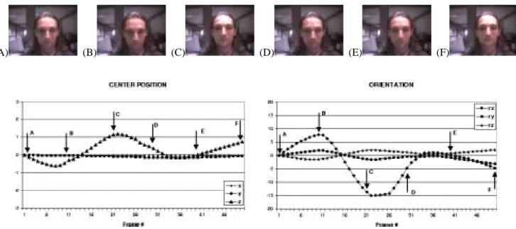
The next example demonstrates using the system for head gesture analysis. We considered two simple head gestures: up-down (nodding yes), back-forth (nodding no). Fig. 5 shows every tenth frame taken from a typical video sequence of a back-forth gesture. Plots of estimated head translation and rotation are shown in the lower part of the figure. Note distinct peaks and valleys in the estimated parameter for rotation around the cylidrical axis; these cor-respond with the extrema of head motion.
Fig. 6 depicts a typical video sequence of an up-down gesture. Again, there are distinct peaks/valleys in graphs of estimated translation and rotation parameters. Note that in this case there appears to be a coupling between the rota-tion around thex-axis and translation along thez-direction (with opposite phase). This coupling is due to the different center of rotation for the head vs. the center of rotation for the cylindrical model. Even with this coupling, the esti-mated parameters are sufficiently distinctive to be useful in discrimination of the two nodding gestures.
In Fig. 7, the head tracker was used to generate a sta-bilized dynamic texture map. Eyebrow raises were then detected using a deformable local texture patch, as de-scribed in Sec. 6. The graph shows the estimated values for the patch vertical stretch parameter. The peaks corre-spond to the three eyebrow raising motions occurring in the sequence. Note that these peak values of the deforma-tion parameter are significantly larger than the mean “rest value.” This makes detection easier. A similar method can be applied to nonrigid tracking of a closed mouth.
In our implementation, the workstation's graphic accel-eration and texture mapping capabilities were used to ac-celerate image warping and rendering; however, the code was not optimized in any other way. Tracking speed av-erages about one second per frame using the difference decomposition, and about seven seconds per frame using Powell. These performance figures include the time needed to extract images from the compressed input movie and to save the stabilized texture map in a movie file.
Figure 4: Example input video frames and head tracking. The frames reported are 17, 23, 24, 39, 40, and 81 (left to right). Note the large amount of motion between two adjacent frames and the occlusions.
(A) (B) (C) (D) (E) (F)
Figure 5: Example input video frames taken from experiments in estimating head orientation and translation parameters: back-forth head gesture (nodding no). Every tenth frame from the sequence is shown. The estimated head orientation and translation are shown in the graphs.
(A) (B) (C) (D) (E) (F)
Figure 6: Second head gesture example: up-down head gesture (nodding yes). Every tenth frame from the sequence is shown. The estimated head orientation and translation are shown in the graphs.
(A) (B)
(C) (D)
(E) (F)
Figure 7:Example of nonrigid tracking in the stabilized dynamic texture map to detect eyebrow raises. The original sequence and tracking deformable texture patch are shown. The graph shows resuling estimates of the patch's vertical stretching parameter.
8
Discussion
In this paper, we presented a technique for 3D head tracking. The dynamic texture image provides a stabi-lized view of the face that can be used for facial expression recognition, lip reading, and other applications requiring that the position of the head is frontal and almost static. We demonstrated our approach for rigid head gesture recogni-tion and nonrigid facial tracking. The precision and speed of the tracker are satisfactory for many practical applica-tions. In our experience, the use of the robust error norm in tracking makes the system almost insensitive to eye blink-ing, and robust to occlusions.
Probably the major weakness of our system is the lack of a backup technique to recover when the track is lost. Us-ing the difference decomposition approach, for sequences with a reasonable amount of head motion, the performance of the tracker gradually decreases after a few hundred frames. Using Powell's technique the long-term stability of the system increases and faster interframe motion can
be tracked. The drawback is that in this case the computa-tional cost increases by an order of magnitude. In any case, a strategy to combat the accumulation error is needed.
In all tests the initial positioning of the model was done by hand. In the future, we plan to use one of the meth-ods presented in literature to automate this step [7]. In our experience, the initial model positioning is not critical; we have run extensive tests to assess the degree of sensitivity to the initial 3D positioning of the model and found that changes up to about 10% in each parameter respect to the “optimal” initial condition affect only slightly the perfor-mance and long term stability of the tracker.
References
[1] A. Azarbayejani, T. Starner, B. Horowitz, and A. Pentland. Visually controlled graphics. PAMI, 15(6), 1993.
[2] S. Basu, I. Essa, and A. Pentland. Motion regularization for model-based head tracking. ICPR, 1996.
[3] M. Black and P. Anandan. The robust estimation of multiple motions: Affine and piecewise-smooth flow fields. TR P93-00104, Xerox PARC, 1993.
[4] M.J. Black and Y. Yacoob. Tracking and recognizing rigid and non-rigid facial motions using local parametric models of image motions. ICCV, 1995.
[5] J.L. Crowley and F. Berard. Multi-modal tracking of faces for video communications. CVPR, 1997.
[6] D. DeCarlo and D. Metaxas. The integration of optical flow and deformable models with applications to human face shape and motion estimation. CVPR, 1996.
[7] I.A. Essa and A.P. Pentland. Coding analysis, interpretation, and recognition of facial expressions. PAMI, 19(7):757– 763, 1997.
[8] P. Fieguth and D. Terzopoulos. Color based tracking of heads and other mobile objects at video frame rates. CVPR, 1997.
[9] M. Gleicher. Projective registration with difference decom-position. CVPR, 1997.
[10] G.D. Hager and P.N. Belhumeur. Real-time tracking of image regions with chenges in geometry and illumination.
CVPR, 1996.
[11] T. Horprasert, Y. Yacoob, and L.S. Davis. Computing 3D head orientation from a monocular image sequence.
Int. Conf. on Face and Gesture Recognition, 1996.
[12] T.S. Jebara and A. Pentland. Prametrized structure from motion for 3D adaptative feedback tracking of faces. CVPR, 1997.
[13] H. Li, P. Rovainen, and R. Forcheimer. 3D motion esti-mation in model-based facial image coding. PAMI, 15(6), 1993.
[14] N. Olivier, A. Pentland, and F. Berard. Lafter: Lips and face real time tracker. CVPR, 1997.
[15] W. Press, B. Flannery, S. Teukolsky, and W. Vetterling.
Nu-merical Recipes in C. Cambridge University Press,
Cam-bridge, UK, 1988.
[16] S. Sclaroff and J. Isidoro. Active blobs. ICCV, 1998. [17] R. Szeliski. Image mosaicing for tele-reality applications.
CRL-TR 94/2, DEC Cambridge Research Lab, 1994. [18] D. Terzopoulos and K. Waters. Analysis and synthesis of
facial image sequences using physical and anatomical mod-els. PAMI, 15(6):569–579, 1993.
[19] Y. Yacoob and L.S. Davis. Computing spatio-temporal rep-resentations of human faces. PAMI, 18(6):636–642, 1996. [20] A.L. Yuille, D.S. Cohen, and P.W. Hallinan. Feature
extrac-tion from faces using deformable templates. IJCV, 8:104– 109, 1992.