A smart wind sensor using thermal sigma-delta
modulation techniques
Ko® A.A. Makinwa
*, Johan H. Huijsing
Electronic Instrumentation Laboratory, DIMES, Delft University of Technology, Mekelweg 4, 2628 CD Delft, The Netherlands
Received 28 June 2001; received in revised form 11 December 2001; accepted 11 December 2001
Abstract
A smart wind sensor realized in a standard CMOS process combines a two-dimensional thermal ¯ow sensor and three auto-zeroed comparators on a single chip. The comparators form the basis of three thermal sigma-delta modulators that control and digitize the heat distribution in the chip. One modulator maintains the chip at a constant temperature above that of the ¯ow, while the other two cancel orthogonal components of a ¯ow-induced temperature gradient. The bit-stream outputs of the modulators are decimated off-chip and used to determine wind speed and direction. Wind tunnel tests show that the sensor is capable of measuring wind speed and direction with an accuracy of4% and28, respectively, over the range 2±18 m/s.#2002 Elsevier Science B.V. All rights reserved.
Keywords:Flow sensor; Thermal sensor; Sigma-delta modulation
1. Introduction
Wind speed and direction can be measured by two-dimen-sional (2-D) thermal ¯ow sensors realized in silicon. Such ``wind sensors'' typically consist of a heated chip [1] or membrane [2,3], which is non-uniformly cooled by the wind. The resulting ¯ow-induced temperature gradient in the sensor is measured by on-chip thermopiles and from this informa-tion both wind speed and direcinforma-tion can be determined.
In typical wind sensors, the output of the thermopiles is small (in the millivolt range), which requires the use of precision (low-offset) interface circuitry. When implemen-ted off-chip, however, such circuitry adds signi®cantly to the cost and complexity of the total sensor system. Furthermore, transporting such small signals off-chip signi®cantly increases their susceptibility to external interference, e.g. from mains and RF sources. For these reasons, efforts have been made to realize ``smart'' thermal ¯ow sensors with co-integrated interface electronics [4±6]. In these designs, a precision ampli®er boosts the thermopile signals to levels compatible with the input range of an analog-to-digital converter (ADC). Since, both a precision ampli®er and an ADC are required, however, this interface architecture requires considerable chip area to implement.
Alternatively, the heat distribution in the sensor can be controlled such that ¯ow-induced temperature differences are cancelled [7]. This technique has the added advantage that the heat distribution in the sensor will always be centered, even in the presence of possible thermal asym-metry introduced during the sensor's fabrication [8]. As described in [7], the heat distribution in the sensor can be controlled using thermal sigma-delta (TSD) modulation techniques. From the resulting heat distribution, both wind speed and direction could be accurately determined. Only three low-offset comparators and some control logic were required to implement the off-chip interface circuitry, result-ing in an area-ef®cient architecture. Furthermore, the inter-face outputs are digital signals (bit-streams) which eliminates the need for an explicit ADC.
In this paper, a smart wind sensor is described which consists of a wind sensor and three low-offset comparators realized on a single CMOS chip. The on-chip comparators, together with a few external components, are used to realize the TSDarchitecture proposed in [7]. The ®rst section of the paper describes the CMOS realization of the wind sensor. This is followed by a description of the interface electronics. Next, the design of the on-chip comparators is described: an auto-zeroed topology was used to achieve suf®ciently low offset in a CMOS process. Finally, the results of electrical measurements and wind tunnel tests on the sensor are presented.
*Corresponding author. Tel.:31-15-278-5747; fax:31-15-278-5755. E-mail address:[email protected] (K.A.A. Makinwa).
0924-4247/02/$ ± see front matter#2002 Elsevier Science B.V. All rights reserved. PII: S 0 9 24 - 4 24 7 ( 0 2) 0 0 0 3 4 - 1
obtained by etching away part of the substrate, as for example in [2,3], experience with a commercial wind sensor shows that this is not required for meteorological applica-tions [9].
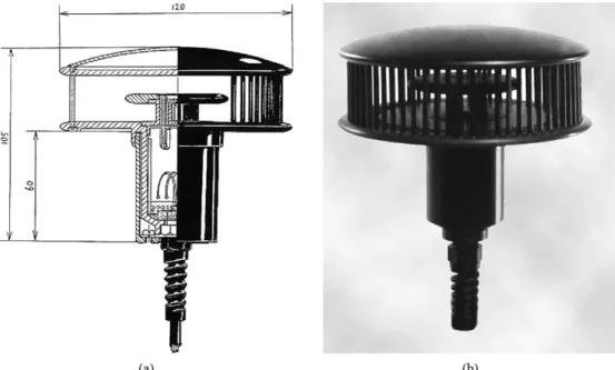
The wind sensor chip is protected from direct contact with the air¯ow to be measured by gluing it to a thin (0.25 mm) ceramic disk, as shown in Fig. 2. The air¯ow is then passed over the opposite side of the disk. Since, ceramic is a good thermal conductor, a measurable temperature gradient will still be induced in the heated chip. Wire-bonded leads connect the chip to a ¯ex foil, which in turn is connected to external circuitry. An opaque encapsulant (glob top) shields the chip from light and protects the sensor and the fragile leads from moisture ingress and oxidation.
The thermopiles sense orthogonal components of the ¯ow-induced temperature gradient. For increased sensitiv-ity, thermopiles on opposite sides of the chip are connected in series since they measure the same component of the temperature gradient. Each thermopile consists of 12p -diffusion/Al thermocouples and has an estimated sensitivity of 6 mV/K and a nominal resistance of 60 KO. The parms of each thermopile are realized in a common n-well,
substrate PNP transistor) is used to measure the average absolute temperature of the chip. When forward biased, its base-emitter voltage has a temperature coef®cient of approximately 2mV/K.
3. Interface electronics
3.1. Operating principle
Each component (dTns or dTew) of the ¯ow-induced
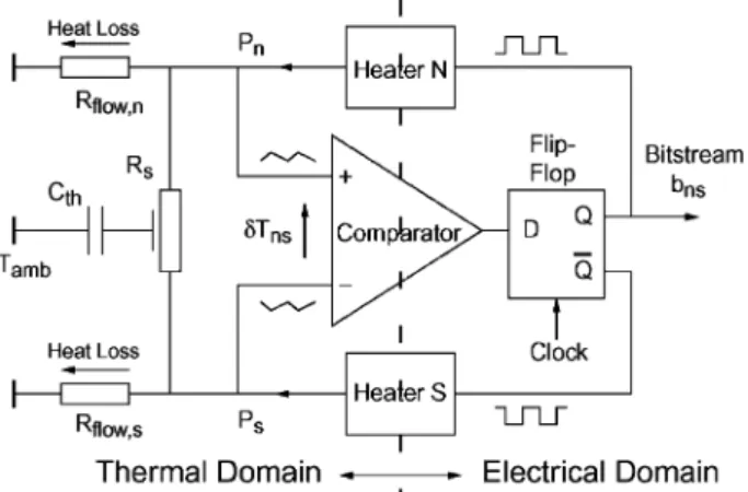
temperature gradient may be accurately cancelled (and, thus measured) by a differential TSDmodulator. The topology of one of these modulators is shown in Fig. 3. Here,Rsis the
thermal resistance between the heaters, andR¯ow,nandR¯ow,s
are ¯ow-dependent resistors that model the sensor's heat loss to the ¯ow.
Intuitively viewed, the modulator attempts to drivedTns
towards zero by applying heat pulses to either the north or south heaters. These pulses will be low-pass ®ltered by the various thermal resistances and the sensor's thermal capa-citance Cth. Then dTns 0, since the clock frequency
greatly exceeds the ®lter's cut-off frequency and the differ-ential heating power dPnsPn Ps balances the sensor's
asymmetric heat loss to the ¯ow. The modulator's bit-stream outputbnsthen represents the normalized differential power dPns/Pref, wherePref is the power dissipated during a heat
pulse.
In a similar manner, the east±west temperature difference is cancelled by a second TSDmodulator which applies heat pulses to either the east or west heaters.
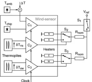
Fig. 1. Schematic layout of a CMOS wind-sensor.
3.2. System architecture
A block diagram of the wind-sensor system is shown in Fig. 4. Each differential modulator consists of a latched comparator, connected to each thermopile pair, which drives the appropriate heaters via external switches (S2or S3) from
a reference voltageVref. The resistorsRnom(with a resistance
equal to the nominal heater resistance) stabilize heater power dissipation against variations in heater resistance due to temperature and process spread [5]. With S1closed,
two of the four heaters will always be ``on'' at any given time and, therefore, the total heat dissipated in the sensor will be constant. The differential modulators thus operate the sensor in a constant power (CP) mode.
The sensor may also be operated in a constant temperature difference (CTD) mode, where it is maintained at a constant overheat with respect to the ¯ow. Compared to operation in CP mode, this results in improved transient response, since the sensor's temperature no longer has to change (and settle) in response to sudden changes in wind speed. To facilitate operation in CTD mode, a voltage proportional to the ¯ow temperatureTamb plus a constant overheat DT,
is generated with the help of an off-chip diode. Comparator C1 then compares this voltage with the output of the on-chip diode. This comparator, together with the thermal ®lter constituted by the entire chip, forms a third, com-mon-mode TSD modulator that (via S1) interrupts the CP heating process in such a way as to maintainTchip TambDT.
4. Low-offset comparator design
4.1. Design considerations
For the differential modulators to operate correctly, the comparator's input offset must lie within the output range of the thermopile pairs. Since, silicon is a good thermal
con-ductor, the on-chip temperature differences are small (milli-Kelvins) and so are the thermopile signals (microvolts). Thermal asymmetries introduced by the sensor's packaging also introduce offset, typically equivalent to a comparator offset of 20mV [1]. In order to reduce comparator offset below this level, an auto-zero scheme was used. As an added bene®t, this scheme also eliminates 1/f noise.
4.2. Comparator architecture
The block diagram of the low-offset comparator is shown in Fig. 5. It uses a classic architecture [10,11] in which the output-referred offset of the ®rst stage and the input-referred offset of the second stage are stored on the capacitors in an auto-zero phase. The main source of residual offset is then the mismatch in charge injection from the switches around the second stage. A fully differential topology was used to cope with the expected ground ``bounce'' produced by the large heater currents. The input stage of the comparators consists of large PMOS devices for low noise and low initial offset. An output latch generates TTL-compatible levels and holds the comparator's previous state during the auto-zero phase.
5. Results
The wind sensor was implemented in a 1.6mm CMOS process, Fig. 6. The interface electronics dissipates about 1 mW from a 5 V supply. In contrast, the heaters dissipate 0.6 W when the sensor is operated in CP mode and between 0.4 and 0.6 W (depending on wind speed) when the sensor is operated in CTD mode. Therefore, the heat produced by the on-chip electronics does not interfere signi®cantly with the sensor's operation.
A power spectrum of the output of a differential mod-ulator (CP mode, zero ¯ow) is shown in Fig. 7. The modulator clock frequency is 8192Hz. The noise shaping produced by the thermal low-pass ®lter is clearly visible. At low frequencies, the ®lter's ®nite gain causes the quantiza-tion noise spectrum to ¯atten. No 1/f noise is visible, demonstrating the effectiveness of the auto-zero scheme. The non-zero dc component is due to mainly thermal
Fig. 4. Block diagram of the wind-sensor system.
air¯ow over the inner disk in a well-de®ned manner. The output of the differential modulators was decimated exter-nally by a 5000-tap sinc2®lter, followed by a 10-tap
moving-average ®lter.
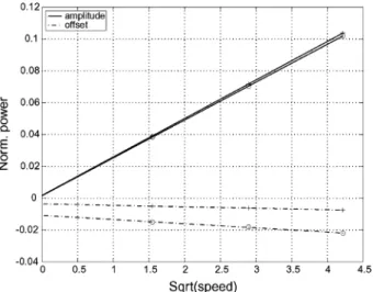
In CTD mode, the decimated modulator outputs are sinusoidal functions of wind direction, Fig. 9. The amplitude and offset of these functions are proportional to the square root of ¯ow speed, Fig. 10. Using these relationships, wind speed and direction were computed from the output of the differential modulators [7]. The results are shown in Fig. 11. It may be seen that the errors are random and less than4% and 28 in wind speed and direction, respectively. These results are similar to the performance of similar sensors using external interface electronics [8,9]. This shows that the presence of the on-chip electronics does not affect the performance of the sensor.
The sensor was also tested in CP mode, i.e. with the common-mode modulator disabled. In this mode, the deci-mated modulator outputs are also sinusoidal functions of wind direction. However, the sensor's amplitude character-istic, while remaining well de®ned and monotonic, is a more complex function of wind speed than it is in CTD mode [12]. However, the errors in the computed wind speed and direc-tion are similar.
Fig. 6. Chip photo of the wind-sensor (4 mm4 mm).
Fig. 7. Hann windowed, 16averaged, 32,768 point, power spectrum of the bit-stream bns.
6. Conclusions
A ``smart'' wind-sensor has been realized in standard CMOS technology. The on-chip interface electronics uses thermal sigma-delta modulation techniques to control, and simultaneously digitize the two-dimensional ¯ow-depen-dent heat distribution in the sensor. This interface architec-ture is low power and area ef®cient, and does not interfere thermally with the sensor's operation or increase its chip area. The interface's bit-stream output is decimated off-chip and used to determine wind speed and direction. The results are accurate to within 4% and 28 in wind speed and direction, respectively, over the range 2±18 m/s.
Acknowledgements
The authors thank the Dutch Technology Foundation (STW) for their ®nancial support and Mierij Meteo B.V. for their assistance with the wind tunnel experiments.
References
[1] B. van Oudheusden, J.H. Huijsing, An electronic wind meter based on a silicon flow sensor, Sens. Actuators A 21±23 (1990) 420±424. [2] J. Robadey, O. Paul, H. Baltes, Two-dimensional integrated gas flow sensors by CMOS IC technology, J. Micromech. Microeng. 5 (1995) 243±250.
[3] B. van Oudheusden, A.W. van Herwaarden, High-sensitivity 2-D flow sensor with an etched thermal isolation structure, Sens. Actuators A 21±23 (1990) 425±430.
[4] E. Yoon, K.D. Wise, An integrated mass flow sensor with on-chip CMOS interface circuitry, IEEE Trans. Electron. Devices 39 (6) (1992) 1376±1386.
[5] Q. Huang, C. Menolfi, C. Hammerschmied, A MOSFET-only interface for integrated flow sensors, Proc. ISCAS (1996) 372±376. [6] F. Mayer, A Haberli, H. Jacobs, G. Ofner, O. Paul, H. Baltes,
Single-chip CMOS Anemometer, Proc. IEDM (1997) 895±898.
[7] K.A.A. Makinwa, J.H. Huijsing, A wind-sensor interface using thermal sigma-delta modulation techniques, Sens. Actuators A 92 (2001) 280±285.
[8] B.W. van Oudheusden, Silicon thermal flow sensor with a two-dimensional direction sensitivity, Measure. Sci. Technol. 1 (1990) 565±575.
[9] Mierij Meteo B.V., Solid-state wind-sensor MMW-005, Product Data sheet,http://www.mierijmeteo.nl.
[10] D.J. Allstot, A precision variable-supply CMOS comparator, IEEE J. Solid-state Circuits SC-17 (1982) 1080±1087.
[11] B. Razavi, B. Wooley, Design techniques for high speed, high-resolution comparators, IEEE J. Solid-state Circuits SC-27 (1992) 1916±1926.
[12] K.A.A. Makinwa, J.H. Huijsing, Constant power operation of a two-dimensional flow sensor using thermal sigma-delta modulation techniques, Proc. IMTC (2001) 1577±1580.
Biographies
Kofi A.A. Makinwawas born on 3 April 1964. He studied at the Obafemi Awolowo University, Ile-Ife, Nigeria, where he received a BSc degree (first class honours) in 1985 and an MSc degree in 1988, both in electronic Fig. 9. Decimated modulator output dPns (*) and dPew () vs. flow
direction at speeds of 2, 8 and 18 m/s.
Fig. 10. Amplitude and offset ofdPns(*) anddPew() vs. the square root of flow speed.
Fig. 11. Errors in computed wind speed and direction at wind speeds of 2, 8 and 18 m/s.
degree in electrical engineering from the Delft University of Technology, Delft, The Netherlands in 1969, and the PhD degree from this university in 1981 for his thesis on operational amplifiers. He has been an assistant
and analysis of analog integrated circuits. He was awarded the title of Simon Stevin Meester for applied Research by the Dutch Technology Foundation.