Deriving (MO)(I)CCCII Based Second-order Sinusoidal
Oscillators with Non-interactive Tuning Laws using State
Variable Method
Abhirup LAHIRI
36-B, J and K Pocket, Dilshad Garden, Delhi, India [email protected]
Abstract. The paper discusses systematic realization of second-order sinusoidal oscillators using multiple-output second-generation current controlled conveyor (MO-CCCII) and/or its inverting equivalent, namely the multiple-output inverting second-generation current controlled conveyor (MO-ICCCII) by state variable method. State variable method is a powerful technique and has been used exten-sively in the past to realize active RC oscillators using a va-riety of active building blocks (ABB). In this work, a non-interactive relationship between the condition of oscillation (CO) and the frequency of oscillation (FO) has been chosen priori and then state variable method is applied to derive the oscillators with grounded capacitors. All the resulting oscillator circuits, eight of them, are “resistor-less”, em-ploy grounded capacitors and do not use more than three (MO)(I)CCCIIs. PSPICE simulation results of a possi-ble CMOS implementation of the oscillators using 0.35µm TSMC CMOS technology parameters have validated their workability.
Keywords
Sinusoidal oscillators, multiple-output second-generation current controlled conveyor (MO-CCCII), multiple-output second-generation inverting current controlled conveyor (MO-ICCCII), state variable method.
1. Introduction
There has been an increasing interest in the design of “resistor-less” and electronically tunable sinusoidal oscilla-tors in the last two decades. Such circuits do not require external linear resistors, provide electronic tunability to the circuit parameters, namely the condition of oscillation (CO) and the frequency of oscillation (FO) and are also benefi-cial for compensating the process induced variations. Sev-eral realizations of “resistor-less” sinusoidal oscillators have been reported in the literature. This includes realizations us-ing operational transconductance amplifiers (OTAs) [1]-[3],
second-generation current-controlled conveyor (CCCII) [4]-[5] and hybid OTA-CCCII elements like current controlled current differencing transconductance amplifier (CCCDTA) [6]-[8]. It is also desirable to construct the circuit using commercially available active elements rather than hypo-thetical ones [9]. Single-resistance-controlled (SRC) type oscillators are preferred choice for variable frequency os-cillators. The realizations in [1], [4]-[7] are based on the SRC type oscillators where each individual resistor is sim-ulated by either a transconductance gm element (in
OTA-based oscillators) or by parasitic resistanceRx (in
CCCII-based oscillators). It is well known that any second-order active RC oscillator circuit providing independent control to the CO and the FO would require at least three resistors and two capacitors (canonicity). Similarly, it can be argued that any second-order “resistor-less” active C oscillator provid-ing non-interactive CO and FO controls would require two capacitors and three resistor simulating elements [9]. Sev-eral systematic methods have been devised over the years to derive such SRC type oscillators, e.g. the state variable method used by Senani et al in [9]-[11] and nodal admit-tance matrix (NAM) used by Soliman in [12]. Perhaps, the most researched SRC-type oscillators [13]-[15] (also in [9]-[12]) are the ones which are defined by the following tuning laws CO: R1=R2, (1) FO: fo= 1 2π r 1 C1C2R1R3 . (2)
In this paper, we deal with SRC-type oscillators which are governed by the following tuning laws
CO: C1R1=C2R2, (3) FO: fo= 1 2π r 1 C1C2R1R3 . (4)
In the recent communication in [9], a variety of sinu-soidal oscillators have been derived using SVA which can be summarized as follows:
• Circuits in Fig. 3(a), 3(b) are governed by tuning laws as in (1) and (2) provided here which have also been researched previously by Senani et al in [10] and [11].
• Circuits in Fig. 3(c), 3(d) are governed by non-independent CO and FO tuning (all the terms in the FO and also present in the CO) and which can be made independent only under the capacitor matching condi-tion.
• Circuit in Fig. 3(e) is a minimum component oscillator (2gm-2C oscillator), but the tuning laws are interactive and independent tuning of the CO and the FO is not possible via transconductances.
To conclude, the oscillators in [9] either report circuits based on tuning laws of (1) and (2) or circuits involving non-independent CO and FO tuning via transconductance (with-out any component matching). Several oscillator realiza-tions governed by (3) and (4) are also available in the lit-erature, e.g. using unity gain cells in [15], recently pro-posed oscillators using current feedback amplifiers (CFOAs) in [18] and [19] and using CCCDTA in [7]. In this paper, we use state variable method of [10] to systematically de-rive “resistor-less” second-order oscillators using multiple-output second-generation current controlled current con-veyor (MO-CCCII) and/or its inverting equivalent, namely the multiple-output inverting second-generation current con-trolled conveyor (MO-ICCCII), which are governed by (3) and (4). The parasiticx terminal resistances of CCCII or ICCCII simulate resistors (tunable via the bias current) and thereby avoiding any use of external resistors. The result-ing circuits employ three (MO)(I)CCCIIs and two grounded capacitors. The realizations are compact and suitable to be implemented in standard bipolar or CMOS technology using the many available realizations of CCCII [20]-[21]. PSPICE simulation results using CMOS implementation of the cir-cuit with 0.35µmTSMC CMOS technology parameters, has been included to verify its workability.
2. Oscillator Synthesis via State
Variable Method
The method of synthesis of second-order sinusoidal os-cillators has been dealt with extensively in [9]-[11] and [14] and here we restate the important steps. In general, a second-order oscillator can be characterized by means of the follow-ing matrix equation
[ dV1 dt dV2 dt ] = a11 a12 a21 a22 V1 V2 =A V1 V2 (5) whereV1andV2are the state variables and are the voltages across the two capacitorsC1andC2, respectively. From (5), the characteristic equation (CE) of the oscillator is given as
s2−s(a11+a22) + (a11a22−a12a21) =0. (6)
It is evident from (6), that the CO and the FO are given as CO: a11=−a22, (7) FO: fo= 1 2π √ a11a22−a12a21. (8) Now comparing (7) and (8) with the desired tuning laws as in (3) and (4) (with the resistorsRi being simulated by
par-asitic resistanceRxi, wherei=1,2,3), we can derive differ-ent matricesAkby appropriately choosing the parametersai j
(wherei=1,2). Working on different combinations, we de-rive the following matrices that confirm with the tuning laws in (3) and (4): A1= h C1 1Rx1 − 1 C1( 1 Rx2 +R1 x3 ) 1 C2Rx1 − 1 C2Rx2 i , (9) A2= h C1 1Rx1 1 C1( 1 Rx2 + 1 Rx3) − 1 C2Rx1 − 1 C2Rx2 i , (10) A3= h −C1 1Rx1 − 1 C1( 1 Rx2 + 1 Rx3) 1 C2Rx1 1 C2Rx2 i , (11) A4= h −C1 1Rx1 1 C1( 1 Rx2 + 1 Rx3) − 1 C2Rx1 1 C2Rx2 i , (12) A5= h C1 1Rx1 − 1 C1Rx1 1 C2( 1 Rx2 + 1 Rx3) − 1 C2Rx2 i , (13) A6= h C1 1Rx1 1 C1Rx1 −C1 2( 1 Rx2 + 1 Rx3 ) −C1 2Rx2 i , (14) A7= h −C1 1Rx1 − 1 C1Rx1 1 C2( 1 Rx2 + 1 Rx3) 1 C2Rx2 i , (15) A8= h −C1 1Rx1 1 C1Rx1 −1 C2( 1 Rx2 + 1 R3) 1 C2Rx2 i (16)
whereRxi represents the xterminal parasitic resistance of theith CCCII or ICCCII and which simulates bias current tunable resistor. Thus, a total of eight different oscillator circuits are realized (corresponding to eachAkmatrix).
Ma-tricesA1−A4are grouped into class A and matricesA5−A8 are grouped into class B, since all the matrices in a particular class have the similar parameters which differ only in their signs, i.e. |ai j|is same for all matrices in a class (A or B).
For class A, it is sufficient to give MO-CCCII based realiza-tion of any one of the matrix in the class and the rest can be derived by simple interchange of sign of the output cur-rent, i.e. by utilizing eitherz+orz−terminal of MO-CCCII. Class B offers some more interesting circuits which cannot be directly created using CCCII and the use of ICCCII is re-quired. It is sufficient to give circuit realization of any one matrix fromA5/A8pair and fromA6/A7pair (and the circuit realization of the other matrix in a pair can be easily obtained by simple interchange ofz+orz−terminal). It is interesting to note that all matrices within class B necessitate the use of floating resistor simulatorsRx1andRx2; further, circuit real-izations of pairA6/A7pair would also necessitate the use of
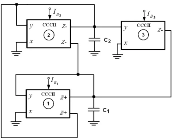
ICCCII . Showing only the necessary and sufficient realiza-tions, we choose matrixA1,A5andA6as example matrices and provide the corresponding MO-CCCII or MO-ICCCII based oscillator realization while employing only grounded capacitors. The resulting circuits corresponding to matrix A1,A5andA6are shown in Fig. 1, Fig. 2 and Fig. 3, respec-tively.
Fig. 1.Oscillator derived fromA1.
Fig. 2.Oscillator derived fromA5.
Fig. 3.Oscillator derived fromA6.
3. Discussion on Parasitics Influence
Since the main purpose of the paper is to use state-variable method in realizing “resistor-less” second-order os-cillators, we very briefly describe the the effects of CCCII parasitics by taking one particular example.
Consider the circuit shown in Fig. 1, derived from ma-trixA1. The parasitic capacitancesCy2,Cz2 andCy3 appear in parallel with the external capacitorC1and similarly, the parasitic capacitancesCy1,Cz1,Cz2 andCz3 appear in par-allel with the external capacitor C2. Thus, it is required that the value of the external capacitors should be larger than the parasitics appearing in shunt to alleviate their ef-fects. Also, parasitic output resistances appear between the high output impedancezterminals and ground and they ap-pear in shunt with the external capacitors. Since it is re-quired that this impedance remains capacitive in nature, the effects can be alleviated by considering the operating fre-quency fo>> 2πC1
iRzi (wherei=1,2) andCirepresents the external capacitor andRzi represents the net parasitic
resis-tance in shunt with the external capacitor. As is evident, this directly limits the low frequency potential of the circuits. It should also be noted that the presence of parasitic capaci-tances in parallel with the external capacitors modify the CO (since both capacitor terms are directly involved) and thus depending on the values of external capacitors and parasitic capacitances appropriate start-up margin should be consid-ered for the oscillator to start. As pointed earlier, choosing external capacitors much larger than parasitic capacitances is a good practise. The non-ideal analysis and effects of par-asitics is not considered for each and every circuit; however, it is believed that the aforementioned parasitic effects can be generally applied to any circuit and can bring about impor-tant results regarding the choice of external passive compo-nents or frequency potential.
4. Simulation Results
The proposed oscillator circuits have been simulated in PSPICE using a possible MOSFET implementation of CCCII, as shown in Fig. 4 (depicting a dual complimentary output CCCII). The oscillator circuit shown in Fig. 2 is taken as the design example. The circuit is implemented using 0.35µm TSMC CMOS technology [22] with±2.5 voltage supplies. From Fig. 4, it can easily be derived that the para-sitic resistance at terminalxis related to the bias currentIB
according to the following equation Rx= r 1 8kIB where k=µpCox W L 1,2=µnCox W L 3,4. (17) The aspect ratios of the transistors in for CCCII are in-dicated in Tab. 1. The circuit is designed with capacitor val-ues ofC1=C2=1 nF. The bias currents are taken to be
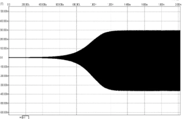
IB1=IB3=150 µA and IB2=149 µA for the start-up of oscillations (so that the loop gain is greater than unity and the oscillations build). Note, that no external auxiliary am-plitude control circuitry is used to stabilize the amam-plitude. The amplitude is inherently limited due to the non-linearity of the active device. The start-up of oscillations and the steady-state waveforms for the voltages across the capaci-tors are shown in Fig. 5 and 6, respectively. It should also be noted that external voltage buffers are needed to use the voltages across the capacitors without loading the circuit, but, such an overhead cost is inevitable in any current con-veyor based oscillator (since they do not offer any buffered terminals for voltage outputs). The observed frequency of 499 kHz is in close correspondence with the theoretical value of 510.43 kHz. The magnitudes of the harmonics obtained using Fourier analysis are shown in Tab. 2, with the total harmonic distortion (THD) of 0.054 % (in terms of power) and 2.42 % (in terms of voltage). The variation of FO with bias currentIB3is shown in Fig. 7, indicating the indepen-dent electronic tuning of the oscillator. Note that value of THD for the performed experiment may not be acceptable
MOSFET W/L (µm/µm)
M1-M2 45/0.35
M3-M4 15/0.35
M5-M6, M11-M12, M14, M16-M17 30/0.35 M7-M8, M9-M10, M13, M15, M18-M19 10/0.35
Tab. 1.Transistor aspect ratios for CCCII.
Freq(Hz) Mag Norm. Mag
1 0.0 (offset) -28.905m -2 499 k 328.007 m 1.000 3 998 k 7.388 m 22.524 m 3 1.497 Meg 1.302 m 3.971 m 4 1.996 Meg 668.851 u 2.039 m 5 2.495 Meg 399.092 u 1.217 m 6 2.994 Meg 295.163 u 899.867 u 7 3.493 Meg 616.168 u 1.880 m 9 3.992 Meg 348.837 u 1.067 m 10 4.491 Meg 202.488 u 617.327 u Tab. 2.Fourier analysis.
Fig. 4.A possible CMOS implementation of complimentary output CCCII.
for some applications in which case auxiliary amplitude con-trol should be used. A very simple way (a very commonly used technique) of regulating the amplitude is to increaseIB2 with increase in amplitude and thereby reducing the positive feedback action. This can be done by sensing the growing amplitude by means of a peak-detector circuit and then in-creasing the bias voltage from whichIB2 is derived. This results in reduced amplitude of oscillation and thus reduced effect of the device non-linearity; yielding a better THD per-formance. Similar methods have been used in recent com-munications in [23]-[24].
Fig. 5.The start-up of oscillations.
Fig. 6.The steady-state oscillation waveform.
100 150 200 250 400 450 500 550 600 650 700
Bias Current IB3 (uA)
Frequency (kHz)
5. Concluding Remarks
State variable method is a powerful technique in real-izing sinusoidal oscillators with priori known tuning laws for the CO and the FO. This paper exhibits the useful-ness of state variable method in realizing MO-CCCII based “resistor-less” sinusoidal oscillators with non-interactive (in-dependently controllable) tuning laws for the CO and the FO. Eight different matrices are systematically developed from the information of the targeted CO and FO and cor-respondingly eight different oscillator circuits are derived, all of which employ grounded capacitors and no more than three MO-CCCIIs and therefore leading to canonic realiza-tions. The method is direct, can be further extended to other oscillator topologies governed by different tuning laws and helps in systematic evolution of oscillators.
Acknowledgements
The author would like to thank the anonymous review-ers for useful suggestions and comments, which helped to improve the paper. The author is also grateful to Dr. Tomas Kratochvil, the executive editor of Radioengineering Journal for enabling the prompt review of the paper.
References
[1] SENANI, R., TRIPATHI, M. P., KUMAR, B. A. Systematic genera-tion of OTA-C sinusoidal oscillators.Electronics Letters, 1990, vol. 26, no. 18, p. 1457-1458.
[2] BARRANCO B. L. et al. CMOS OTA-C high-frequency sinusoidal oscillators.IEEE Journal of Solid-State Circuits, 1991, vol. 26, no. 2, p. 160-165.
[3] KUMNGERN, M., DEJHAN, K. OTAs-Based current-mode quadra-ture oscillator. In Proceedings of International Symposium on In-telligent Signal Processing and Communication Systems (ISPACS). Bangkok (Thailand), 2008.
[4] MAHESHWARI, S., KHAN, I. A. Novel voltage/current-mode translinear-C quadrature oscillator.Journal of Active and Passive Electronic Devices, 2007, vol. 2, no. 3, p. 235-239.
[5] MAHESHWARI, S. Electronically tunable quadrature oscillator us-ing translinear conveyors and grounded capacitors.Active and Pas-sive Electronic Components, 2003, vol. 26, p. 193-196.
[6] JAIKLA, W., SIRIPRUCHYANAN, M. A versatile quadrature oscil-lator and universal biquad filter using dual-output current controlled current differencing transconductance amplifier. InProceedings of International Symposium on Communications and Information Tech-nologies - (ISCIT). Bangkok (Thailand), 2006, p. 1072-1075. [7] LAHIRI, A., MISRA, A., GUPTA, K. Novel current-mode
quadra-ture oscillators with explicit-current-outputs using CCCDTA. In Pro-ceedings of 19th International Conference Radioelektronika 2009. Bratislava (Slovakia), 2009, p. 47-50.
[8] BIOLEK, D., SENANI, R., BIOLKOVA, V., KOLKA, Z. Active el-ements for analog signal processing: Classification, review, and new proposals.Radioengineering, 2008, vol. 17, No. 4, p. 15-32. [9] PETRZELA, J., VYSKOCIL, P., PROKOPEC, J. Fundamental
os-cillators based on diamond transistors. InProceedings of 20th Inter-national Conference Radioelektronika 2010. Brno (Czech Republic), 2010.
[10] SENANI, R., GUPTA, S. S. Synthesis of single-resistance-controlled oscillators using CFOAs: simple state-variable approach.IEE Pro-ceedings – Circuits, Devices and Systems, 1997, vol. 144, p. 104-106.
[11] GUPTA, S. S., SENANI, R. State variable synthesis of single re-sistance controlled grounded capacitor oscillators using only two CFOAs.IEE Proceedings – Circuits, Devices and Systems, 1998, vol. 145, p. 135-138.
[12] SOLIMAN, A. M. Generation of current conveyor based oscillators using nodal admittance matrix expansion. Analog Integrated Cir-cuits and Signal Processing, 2010, vol. 65, no. 1, p. 43-59, DOI: 10.1007/s10470-009-9432-5.
[13] MARTINEZ, P., SABADELL, J., ALDEA, C., CELMA, S. Variable frequency sinusoidal oscillators based on CCII”.IEEE Transactions on Circuits and Systems - I, 1999, vol. 46, no. 11, p. 1386-1390. [14] SOLIMAN, A. M. Synthesis of grounded capacitor and grounded
re-sistor oscillators.Journal of the Franklin Institute, 1999, vol. 336, p. 735-746.
[15] LAHIRI, A. New realizations of voltage-mode quadrature oscillators using current differencing buffered amplifiers.Journal of Circuits, Systems and Computers, 2010, vol. 19, no. 5, p. 1069-1076, DOI: 10.1142/S0218126610006608.
[16] LAHIRI, A. Explicit-current-output quadrature oscillator using second-generation current conveyor transconductance amplifier. Ra-dioengineering, 2009, vol. 18, no. 4, p. 522-526.
[17] GUPTA, S. S., SENANI, R. New single resistance controlled oscil-lators employing a reduced number of unity-gain cells.IEICE Elec-tronics Express, 2004, vol. 1, no. 16, p. 507-512.
[18] GUPTA, S. S., SHARMA, R. K., BHASKAR, D. R., SENANI, R. Sinusoidal oscillators with explicit current output employing current-feedback op-amps.International Journal of Circuit Theory and Ap-plications, 2010, vol. 38, no. 2, p. 131-147, DOI: 10.1002/cta.531. [19] TANGSRIRAT, W., SURAKAMPONTORN, W.
Single-resistance-controlled quadrature oscillator and universal biquad filter using CFOAs. AEU- International Journal of Electronics and Communications, 2009, vol. 63, no. 12, p. 1080-1086, DOI:10.1016/j.aeue.2008.08.006.
[20] SAGBAS, M., FIDANBOYLU, K. Electronically tunable current-mode second-order universal filter using minimum elements. Elec-tronics Letters, 2004, vol. 40, no. 1, p. 2-4.
[21] CHEN, H. P., CHU, P. L. Versatile electronically tunable current-mode filter using CCCIIs.IEICE Electronics Express, 2009, vol. 6, no. 2, p. 122-128.
[22] YUCE, E. On the implementation of the floating simulators employ-ing a semploy-ingle active device.AEU- Interntational Journal of Electronics and Communications, 2007, vol. 61, p. 453–458.
[23] BAJER, J., BIOLEK, D. Digitally controlled quadrature oscillator employing two ZC-CG-CDBAs.Proceedings of the 16th Interna-tional Conference on EDS-IMAPS. Brno (Czech Republic), 2009, p. 298-303.
[24] BAJER, J., LAHIRI, A., BIOLEK, D. Current-mode CCII+ based os-cillator circuits using a conventional and modified wien-bridge with all capacitors grounded.Proceedings of the 17th International Con-ference on EDS-IMAPS. Brno (Czech Republic), 2010, p. 5-10.
About Author. . .
Abhirup LAHIRI, for biography see page 249 of the cur-rent issue.