Self-Balancing Robot
B.N.Naveen kumar
1, Manjunatha Bhat
2, V.Maruthi kumar
3and K.S. Meera
41UG Student, Department of ECE, MVJ College of Engineering, Whitefield, Bengaluru, Karnataka, India. 2UG Student, Department of ECE, MVJ College of Engineering, Whitefield, Bengaluru, Karnataka, India. 3UG Student, Department of ECE, MVJ College of Engineering, Whitefield, Bengaluru, Karnataka, India. 4Assistant Professor, Department of ECE, MVJ College of Engineering, Whitefield, Bengaluru, Karnataka, India.
Article Received: 16 May 2017 Article Accepted: 04 June 2017 Article Published: 06 June 2017
1. INTRODUCTION
Robotics has always been played an integral part of the human psyche. The dream of creating a machine that replicates
human thought and physical characteristics extends
throughout the existence of mankind. Developments in technology over the past fifty years have established the foundations of making these dreams come true. Robotics is now achievable through the miniaturization of the microprocessors which performs the processing and computations. New forms of sensor devices are being developed all the time further providing machines with the ability to identify the world around them in so many different ways.
Effective and efficient control system designs provide the robot with the ability to control itself and operate autonomously. Artificial intelligence (AI) is becoming a definite possibility with advancements in non-linear control systems such as neural networks and fuzzy controllers. Improved synthetics and materials allow for robust and cosmetically aesthetic designs to be implemented for the construction and visual aspects of the robot. Two wheeled robots are one variation of robot that has become a standard topic of research and exploration for young engineers and robotic enthusiasts.
They offer the opportunity to develop control systems that are capable of maintaining stability of an otherwise unstable system. This type of system is also known as an inverted pendulum. This research project aims to bring this, and many of the previously mention aspects of a robot together into the building of a two wheeled balancing robot with a non-linear, fuzzy controller.
Two wheeled balancing robots
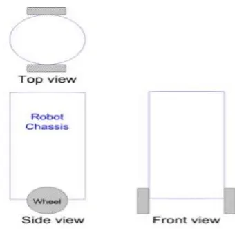
A robot that is capable of balancing upright on its two wheels is known as a two wheeled balancing robot. The following figure contains the physical view for the robot designed as part of this project. The process of balancing is typically referred to as stability control. The two wheels are situated below the base and allow the robot chassis to maintain an upright position by moving in the direction of tilt, either forward or backward, in an attempt to keep the centre of the mass above the wheel axles. The wheels also provide the locomotion thus allowing the robot to transverse across various terrains and environments.
Fig.1. Views of two wheeled balancing robot
This type of robot provides a challenging problem and has resulted in many useful and interesting designs being developed. One such two wheeled robot that has become a commercial success is the Segway by Segway Inc. The immediate impact has been within the personal transportation A B S T R A C T
Two wheeled balancing robots are an area of research that may well provide the future locomotion for everyday robots. The unique stability control that is required to keep the robot upright differentiates it from traditional forms of robotics. The inverted pendulum principle provides the mathematical modelling of the naturally unstable system. This is then utilized to develop and implement a suitable stability control system that is responsive, timely and successful in achieving this objective. Completing the design and development phase of the robot requires careful consideration of all aspects including operating conditions, materials, hardware, sensors and software. This process provides the ongoing opportunity of implementing continued improvements to its perceived operation whilst also ensuring that obvious problems and potential faults are removed before construction
area where an alternative to cumbersome wheelchairs is now available. Segway proves a comfortable mobility opportunity for the elderly or people with disability thus improving their individual sense of independence at the same time. The theory used to maintain stability of these robots is based on the inverted pendulum theory which is covered in the following section.
The two wheeled self-balancing project is based on the
inverted pendulum. The aim of the inverted pendulum
principle is to keep the wheels beneath the centre of the robot chassis’s mass. If the robot begins to tilt forward, then to maintain stability, the wheel will need to move forward to return beneath the chassis mass. If this is not maintained, the robot will simply fall over.
2. RELATED WORK
The self-balancing robot is a system similar to the classical mechanical system of an inverted pendulum on a cart. It is an interesting system to control since it is relatively simple, yet non-linear and unstable. The literature is extensive from hobbyists and academic projects [3, 4, 7]; to advanced commercial products such as the Segway [5]. Optimal control with the LQ controller is often used to solve the problem of stabilizing the unstable robot system without the need for manual tuning of the state-feedback controller [1]. The balancing robot in this paper follows this common technique. Various strategies have been used in similar projects in the past to combine the information from a gyroscope and an accelerometer. A Kalman filter is also used in [1] to arrive at the best estimate for the angle from the available signals. For control of forward velocity of full-sized balancing vehicles, several techniques have been tested. Among them are setting a weighting on the control in the LQR and designing the controller in such a way that it is unable to eliminate the steady-state error caused by the rider leaning on the platform, forcing the controller to apply constant power to the motors which results in forward motion [1]. The robot in this paper does not have the benefit of a rider providing a constant input disturbance to control forward motion, but some similar technique of using a constant steady-state error to motivate forward motion is being considered.
3. REQUIREMENTS AND SPECIFICATIONS
The system requirements are divided into two categories, depending on whether they are considered needed or desired. The robot need to:
• stabilize in an upright position
• reject disturbances, such as gentle pushes • display information useful for debugging It is desired that the robot has
• modes for homing and free drive, i.e. a mode for returning to the initial position and a mode for not caring about which position the robot ends up in.
Fig.2 Hardware architecture of self balancing robot
Components used:
1) Atmega 328 microcontroller
The Atmel 8-bit AVR RISC -based microcontroller combines
32 kB ISP flash memory with read-while-write capabilities, 1 kB EEPROM, 2 kB SRAM, 23 general purpose I/O lines,
32 general purpose working registers, three flexible
timer/counters with compare modes, internal and external
interrupts, serial programmable USART, a byte-oriented
2-wire serial interface, SPI serial port, 6-channels,
programmable watchdog timer with internal oscillator, and five software selectable power saving modes. The device operates between 1.8-5.5 volts. The device achieves throughput approaching 1 MIPS per MHz.
Fig.3 Pin diagram of Atmega 328
2) MPU6050
sensors through an auxiliary master IC bus, allowing the devices to gather a full set of sensor data without the intervention from the system processor.
Fig.4 MPU 6050 IC
3)Motors are an essential component for providing mobility. Without motors to move the machine, it would prove to be an expensive paperweight. Several types of motor are available including Alternating Current (AC) or Direct Current (DC) types. Variances of these motors include the brushless, brush, servo and permanent magnet motors. Another consideration for the motor is its Revolutions Per Minute (RPM). As most motors are rated between 2000-7000 RPM, some form of gearing is required to reduce the rate experienced at the wheel.
The idea of a motor for each side of the robot, also known as differential drive, was decided upon early to reduce the
potential mechanical complication involved with
implementing a single motor system. Using two motors will also allow the torque to be more effectively applied to the wheel shafts thus reducing the need for complex calculations for frictional and rotational losses. Differential drive is displayed in the following figure.
Fig.5. Top view of self-balancing robot
4. WORKING PRINCIPLE
Fig.6. Fusion of all the data obtained by various means
How balancing is done
It will be prevented from falling by giving acceleration to the wheels according to its inclination from the vertical. If the bot gets tilts by an angle, than in the frame of the wheels, the centre of mass of the bot will experience a pseudo force which will apply a torque opposite to the direction of tilt.
Kalman filter
The Kalman filter is a set of mathematical equations that provides an efficient computational (recursive) means to estimate the state of a process, in a way that minimizes the mean of the squared error. The filter is very powerful in several aspects: it supports estimations of past, present, and even future states, and it can do so even when the precise nature of the modelled system is unknown.
The filter is used in control engineering to remove measurement noise that can affect the performance of system under control. It also provides an estimate of the current state of the process or system. The Kalman filter is a tool that can estimate the variables of a wide range of processes. In mathematical terms we would say that a Kalman filter estimates the states of a linear system. The Kalman filter not only works well in practice, but it is theoretically attractive because it can be shown that of all possible filters, it is the one that minimizes the variance of the estimation error.
The process or system that is being measured must be modelled by linear system. A linear system can best be described by the following two state space representation equations:
x(k) = Bu(k-1) + w(k-1) z(k) = H x(k) + v(k)
First equation represents the process state equation. A, B, and H represent the state matrices, the w(k-1) represents the process noise, k is the time index, x(k-1) is the state of the process, and u(k-1) is the known input to the process. Second equation above represents the output state equation. The z(k) represents the measured process output and the v(k) represents the measurement noise. The sensor data for the system are taken at discrete time sample points. The measurements are dependent on the state of the process or system.
Finally what we conclude about Kalman Filter is:
sensors used.
appropriate weightage which will vary according to time.
stage and current state
PID control system
The control algorithm that was used to maintain it balance on the autonomous self-balancing two wheel robot was the PID controller. The proportional, integral, and derivative (PID) controller, is well known as a three term controller.
The input to the controller is the error from the system. The Kp, Ki, and Kd are referred as the proportional, integral, and derivative constants (the three terms get multiplied by these constants respectively). The closed loop control system is also referred to as a negative feedback system. The basic idea of a negative feedback system is that it measures the process output y from a sensor. The measured process output gets subtracted from the reference set point value to produce an error. The error is then fed into the PID controller, where the error gets managed in three ways. The error will be used on the PID controller to execute the proportional term, integral term for reduction of steady state errors, and the derivative term to handle overshoots. After the PID algorithm processes the error, the controller produces a control signal u. The PID control signal then gets fed into the process under control.
The process under PID control is the two wheeled robot. The PID control signal will try to drive the process to the desired reference set point value. In the case of the two wheel robot, the desired set-point value is the zero degree vertical position. The PID control algorithm can be modelled in a mathematical representation
PID is used to calculate the ‘correction’ term:
Correction = Kp*error + Ki* ∫error + Kd* d/dt(error); Kp , Ki and Kd are constants which are set experimentally.
PID Tuning :
Here are some steps which will help to get Kp, Ki and Kd faster:
0, and adjust P so that the robot starts to oscillate (move back and forth) about the balance position. P should be large enough for the robot to move but not too large otherwise the movement would not be smooth.
t accelerates faster when off balance. With P and I properly tuned, the robot should be able to self-balance for at least a few seconds.
balanced position more gentle, and there shouldn’t be any significant overshoots.
Software architecture
The software architecture is divided into a digital control system, a Human Machine Interface (HMI) and an initialization module, shown in Fig. 7. A sampling module reads sensory information at 250 Hz. The sampled data is used by a state estimator that produces state estimates at the same rate.
Fig.7. Software architecture
5. EXPERIMENTAL RESULTS
Fig.9 Tilt angle state generated by Kalman and complementary filter respectively
Fig.10 Linear velocity state generated by Kalman and
complementary filter respectively. Note that the
complementary filter uses one extra sensor (encoder) to achieve its reconstruction.
6. DISCUSSION
In the initial part of the project a number of requirements were formulated for the robot. The requirements were categorized into either a needed requirement or a desired requirement, where the second category was to be done depending on time and success of the needed requirements.
It was defined that the robot needed to be able to stand in upright position and reject disturbances. As seen in previous section both these requirements were fulfilled.
The sensors were one of the most difficult part of the project to get to function properly and also one of the most important. However, when the filter was tuned properly, the control scheme worked well. Since the complementary filter worked well the more complex Kalman filter was not implemented as initially planned.
Another critical factor in the control scheme was the sampling frequency. With a sampling frequency of 100 Hz, no suitable controller could be developed. When the sampling frequency
of 250 Hz was used, at 200 Hz, the system was marginally stable.
The other planned features, such as steering and speed control, have been deemed to be unimportant relative to stabilization and have not yet been implemented
7. CONCLUSION
A fully capable design concept has been developed for the two wheeled balancing robot which will provide the fundamental hardware necessary in achieving the goals outlined by the project. Manufacturing and assembly of the components, circuits and devices will provide the conversion from concept to actual physical robot.
REFERENCES
[1] Mikael Arvidsson and Jonas Karlsson. Design, construction and verification of a self-balancing vehicle.
Online, 2015. http://publications.lib.chalmers.se/records/
fulltext/163640.pdf.
[2] Stephan Blaha, Divij Babbar, Iram Gallegos, and Kubica
Matej. Optimal control project. Online, 2012.
http://www.matejk.cz/zdroje/ nxtway-gs-evaluation.pdf.
[3] Mitch Burkert, Taylor Groll, Thao Lai, Tyler McCoy, and
Dennis Smith. Segway design project. Online, 2004.
http://etidweb.tamu.edu/classes/Entc%20462/Segway/final_re port.pdf.
[4] Sebastian Nilsson. Sjalvbalancerande robot. Online, 2012.
http://sebastiannilsson.com/k/ projekt/selfbalancing-robot/.
[5] Segway. Segway - the leader in personal, green transportation. Online, 2013. http://www.segway.com.
[6] MathWorks Simulink Team. Simulink support package for