IJIRT 142651
INTERNATIONAL JOURNAL OF INNOVATIVE RESEARCH IN TECHNOLOGY96
Differential Relaying Protection of Transmission Line
Interconnecting DG and UPFC using Discrete Wavelet
Transform
Felsy Felix Pereira
1, Emil Ninan Skariah
2 1Student, Saintgits College of Engineering, Kottayam, Kerala.
2
Faculty, Saintgits College of Engineering, Kottayam, Kerala.
Abstract—This paper presents an approximate level Discrete Wavelet Transform (DWT) based differential relaying scheme for a transmission line in the presence of Unified Power Flow Controller (UPFC), Wind farm and Photo voltaic (PV) module. The fault current signals are obtained from respective buses and pre-processing it with the help of approximate level DWT to derive fourth level approximate coefficients (CA4). Further, the RMS value is extracted to compute operating and restraining values for fault detection in such a complex transmission system. The proposed relaying scheme has been extensively tested for wide variations in parameters and operating conditions, and the performance shows that the proposed scheme is highly reliable.
Index Terms—Discrete Wavelet transform (DWT), Photo Voltaic Module, Unified Power Flow Controller (UPFC), Wind-farm.
I. INTRODUCTION
Each and every day the demand for electricity is increasing. The transmission networks are pushed to their physical limits to optimize the operation aspects of generation, transmission and distribution of electric power. Utilities are forced to rely on the already existing networks to meet the electric
demand. Flexible AC Transmission systems
(FACTS) [2] play an important role to reduce the stress involved in the transmission lines. The concept of FACTS refers to a family of power electronic based devices to enhance AC system controllability and stability thus increasing power transfer capability. UPFC has the ability to independently control three important parameters of power system such as bus voltage, line active and reactive power [11]. Even though UPFC is capable of improving the
IJIRT 142651
INTERNATIONAL JOURNAL OF INNOVATIVE RESEARCH IN TECHNOLOGY97
also integrated to such a system conventionaldistance relaying scheme fails to operate.
II. WAVELET TRANSFORM
Wavelet transform is a very effective tool for analysing power transients. WT introduces several applications in the field of fault detection, fault location, high impedance fault etc. A wavelet is a waveform of which have limited duration and with an average value of zero. The original signal known as mother wavelet is dilated and shifted in order to produce daughter wavelets. Wavelet analysis allows the use of both long time intervals and shorter regions in order to cover irregular low frequency and high frequency information. The wavelet transform are of two types continuous wavelet transform (CWT) and discrete wavelet transform (DWT).
Continuous Wavelet Transform (CWT) has been developed as an alternative to Short Term Fourier Transform (STFT) to overcome the resolution problem. The CWT of a signal x(t) is given by,
(1)
where,
is the mother wavelet
a = dilation parameter (scale factor) b = translation parameter.
Discrete Wavelet Transform (DWT) is another special case of WT. It is considerably easier to implement compared to CWT. Even though the idea of computation is same as that of CWT, the time-scale representation of digital signal is obtained using digital filtering techniques. The continuous wavelet transform was computed by changing the scale of the analysis window, shifting the window in time, multiplying by the signal, and integrating over all times. In the discrete case, filters of different cut-off frequencies are used to analyse the signal at different scales. The signal is passed through a series of high pass filters to analyse the high frequencies, and it is passed through a series of low pass filters to analyse the low frequencies.
Fig: 1 An example of three level decomposition The equation to derive the high pass and low pass wavelet coefficients is given by:
(2)
(3)
where,
and are called wavelet filters k is the length of the filter
i = 0,1, … [n/2]-1
In this paper, the current features are extracted by pre-processing the current signals from each of the different substations using wavelet transform. The Daubechies-4 (db4) mother wavelet is selected to produce the daughter wavelets as it is well suited for fault and transient analysis. In the proposed scheme a sampling frequency of 20 kHz (400 samples in a 50Hz system) is considered. The current signal is decomposed into four levels resulting in “a-1 (0-10kHz) and d-1 (10-20kHz)” at level 1, “a-2 (0-5 kHz) and d-2 (5-10 kHz)” at level 2, “a-3 (0-2.5 kHz) and d-3 (2.5-5 kHz)” at level 3 and “a-4(0-1.25 kHz) and d-4 (1.25-2.5kHz)”at level 4. The rms value of the re-constructed signal is used to compute the operating and restraining values.
III. SYSTEM STUDIED
IJIRT 142651
INTERNATIONAL JOURNAL OF INNOVATIVE RESEARCH IN TECHNOLOGY98
Fig: 2 Simulated transmission system.The parameters used for modelling the proposed system are given below:
Transmission line parameter:
= 0.01537(Ω/km): Positive sequence resistance
= 0.04612(Ω/km): Zero sequence resistance
= 0.8858× (H/km): Positive
sequence inductance
= 2.654× (H/km): Zero sequence
inductance
= 13.06× (F/km): Positive sequence
capacitance Source parameter:
= 500 kV (substation-1), 50 Hz, short-circuit level
1500 MVA, =
= 500 kV (substation-2), 50 Hz, 60MW
Wind-farm is connected through a 575 V/500 kV, 70
MVA transformer, = .
= 500 kV (substation-3 voltage), 50 Hz,
short-circuit level 1500 MVA, = .
UPFC is installed in the middle of the transmission line of length 200 km which have a rating of 100 MVA. In the proposed scheme UPFC is operated in automatic control mode since it is the most common mode of operation. The UPFC has two 48-pulse voltage source inverters which are connected with the help of two 2500μF common dc capacitors. The first inverter is STATCOM, which is connected to the transmission system with the help of a ∆/Y shunt transformer of rating 500/20kV. STATCOM helps to inject or consume reactive power to the transmission line and hence regulating the voltage at the connected point. Another inverter Static Synchronous Series
Compensator (SSSC) is connected to the
transmission system with the help of a Y/Y series transformer of rating 20 kV/60 kV to regulate the voltage and power flow through the line.
Wind farm of capacity 60 MW (40 numbers of wind turbines each of capacity 1.5 MW). Wind turbines uses Doubly-Fed induction generator which allows extracting maximum energy from the wind by optimizing the turbine speed, also it minimizes the mechanical stress in turbine during gust of wind. Solar insolation and cell temperature are the main
two parameters that determine the output
characteristics of the PV module. A 36W PV module is taken as the reference module for simulation. The other parameters are as given below,
Rated power = 36W
Total number of cells in series = 36
Total number of cells in parallel = 1
Voltage at maximum power ( ) = 18 V
Current at maximum power ( ) = 4 A
The proposed concept is tested for wide variations in fault parameters and operating conditions as given below:
Different types of fault: Single line fault, Double line fault, Line to ground fault, three phase fault.
Variation in fault resistance( 0-100 Ω
Variation in wind speed: 5-25m/sec
Variation in temperature: 30-150° C
IV. PROPOSED METHOD
IJIRT 142651
INTERNATIONAL JOURNAL OF INNOVATIVE RESEARCH IN TECHNOLOGY99
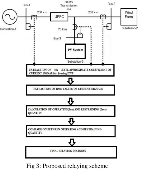
Fig 3: Proposed relaying schemeThe operating and restraining quantity of the differential relay can be calculated as follows:
(4)
(5)
where , , are the reconstructed current
signals of a-phase of substation-1, 2 and 3, respectively. The operating and restraining
quantity is calculated by:
(6)
(7)
where N is the number of samples.
V. RESULTS AND DISCUSSION
Sim-Power Systems is used to model the proposed system. The performance is observed under different fault conditions and also varying parameters.
A. Internal fault
Different types of faults are simulated on the transmission system and the proposed scheme is validated. Fig:4 shows the current waveform when a fault is applied on substation-1 at 0.3 sec.
Fig:4 Current waveform when fault is applied at 0.3sec
Table:1 shows the operating and restraining values obtained for various internal fault conditions. The result shows that is at higher level compared to
Table:1 Internal fault conditions.
Faults (A) (A)
AG 1292 291.9
ABG 386.6 375.6
AB 2279 840.7
ABC 2284 845.4
B. Varying fault Resistance
Faults with high resistance generally affect the performance of the conventional relaying scheme (distance relaying scheme). In order to test the effect of the change in fault resistance ( ), the validation is
carried out for an AG fault with different values of
( = 0-100Ω). Table:2 confirms that the magnitude
of both and are changing as is increasing
from 0 to 100 Ω. However, stays at much higher
level compared to for each fault resistance and
thus, makes the relaying scheme reliable. It has been found that the impact of high resistance fault ( = 0-100Ω) has no significant effect on the performance of the proposed relaying scheme.
Table:2 Effect of varying fault resistance. Fault
resistance(Ω)
(A) (A)
20 2410 1542
40 2412 1540
60 2398 1538
IJIRT 142651
INTERNATIONAL JOURNAL OF INNOVATIVE RESEARCH IN TECHNOLOGY100
C. Varying Wind speed and TemperatureThe output power of a wind farm and PV system has a non-linear relationship with the wind speed and temperature respectively which greatly affect the conventional relaying scheme. The proposed relaying scheme is tested under different wind speed (varies from 5 m/s to 25 m/s) and temperature (varying from 30°C to 150°C) during faulted condition. It is observed that the operating and restraining quantities vary with respect to wind speed as shown in table 3 & 4.
Table 3: Effect of varying wind speed. Wind
speed(m/sec)
(A) (A)
5 2410 1525
10 2411 1534
15 2432 1520
20 2430 1511
25 2405 1525
Table 4: Effect of varying temperature
Temperature(° C) (A) (A)
30 1.9× 968
60 1.95 972
90 1.88 1000
100 1.89 962
150 1.96 985
VII. CONCLUSION
A Discrete wavelet based differential relaying scheme which uses a-4 coefficient of db-4 signal for transmission line protection including UPFC, wind-farm and PV is proposed. The scheme works on the computed operating and restraining signals to issue or
suppress the tripping signal. The proposed
differential scheme is validated for detecting and classifying faults including wide variations in different faults, faults resistance, PV and wind-farm parameters. It is observed that the relaying scheme is highly effective in detecting fault.
REFERENCES
[1] Xiaoyao Zhou, Haifeng Wang, Aggarwal RK, Beaumont Phil, “Performance evaluation of a distance relay as applied to a transmission
system With UPFC”. IEEE Trans Power Del
2006;21(3):1137–47.
[2] Dash PK, Pradhan AK, Panda G, Liew AC, “Adaptive relay setting for flexible AC
transmission systems (FACTS)”. IEEE Trans
Power Del 2000;15(1):38–43.
[3] El-Zonkoly AM, Desouki H, “Wavelet entropy based algorithm for fault detection and
classification in FACTS compensated
transmission line”. Int J Electr Power Energy Syst 2011;33(8):1368–74.
[4] Ghorbani Amir, Mozafari Babak, Ranjbar Ali Mohammad, “Digital distance protection of transmission lines in the presence of SSSC”. Int J Electr Power Energy Syst 2012;43(1):712–9. [5] Pradhan AK, Joos Geza, “Adaptive distance
relay setting for lines connecting wind farms”. IEEE Trans Energy Convers 2007;22(1). [6] Dash PK, Pradhan AK, Panda G, “Distance
protection in the presence of unified power flow controller.” Int J Electr Power Energy Syst 2000;54(3):189–98.
[7] Ito H, Shuto I, Ayakawa H, Beaumont P, Okuno K, “Development of an improved multifunction high speed operating current
differential relay for transmission line
protection”. Int Conf DPSP IEE Conf
2001;479:511–4.
[8]Silveira PM, Seara R, Zurn HH, “An approach using wavelet transform for fault type identification in digital relaying”. IEEE-PES Summer Meeting 1999;2:937–42.
[9]Megahed I, Moussa AM, Bayoumy AE. “Usage
of wavelet transform in the protection of series-compensated transmission lines”. IEEE Trans Power Del Jul 2006;21(3):1213–21.
[10]Badri ram, D N Vishwakarma, “Power system protection and switch gear”.
[11] Hingorani NG, Gyugyi L. “Understanding
FACTS concepts and technology of flexible AC transmission systems”. New York: IEEE Press; 2000.
[12] M.Veerachary,“Power Tracking for Nonlinear
PV Sources with Coupled Inductor SEPIC
Converter,” IEEE Transactions on Aerospace