EFFECT OF STIFFNESS OF SHEAR WALL, STAIRCASE AND
INFILL WALL IN REINFORCED CONCRETE FRAMED
STRUCTURE SUBJECTED TO WIND LOAD USING STAAD.PRO
G.S.V.Brahmaji Rao1, V.Raju21. INTRODUCTION
In general, as the height of a building increases, its overall response to lateral load (such as wind and earthquake) increases. When such response becomes sufficiently great such that the effect of lateral load must be explicitly taken into consideration in design, a multistory building is said to be tall. Tall buildings are prone to excessive displacements, necessitating the introduction of special measures to contain these displacements. The lateral load effects on buildings can be resisted by Frame action, Shear Walls, or Dual System. Peak inter-storey drift and lateral displacement (or side sway) are two essential parameters used for assessing the lateral stability and stiffness of lateral force resisting systems of tall buildings. Selection of such a strong and stiff enough deformation resisting systems that will curtail the drift within acceptable code limits should be the main motive of structural designers. As it is well known to most of structural engineers who are familiar with the types of structural systems for resisting wind and seismic loads, they are called Shear systems such as-
1.1 Frames:
This is a frame system of rigid beams subjected to lateral loads where the developed moments in the middle of the columns are not existent and the shear forces will be distributed proportionally with the moment of inertia of the columns and the lateral displacements will be proportional to these forces.
1.2 Shear walls:
These systems resist the lateral loads with the shear walls whether these walls are separated or connected by beams.
The distribution of shear forces is proportional to the moment of inertia of the cross sections of the walls; the displacements in each floor or level are the result of the flexural deformations in the walls.
1.3 Dual systems
These systems are the result of combining the two latter systems to resist the lateral load, in these systems the shape of the deformations will differ from those in frames and walls systems, where effecting interacted forces occur and change the shape of shear and moment diagrams. One of the advantages of this combination is that the frames support the walls at the top and control their displacement. Besides, the walls support the frames at the bottom and decrease their displacement.
2. LITERATURE RIEVIEW
J Lavado et al (2004) suggested that under seismic loading, the effect of staircase can be very important in structures, constituted by frames. Study on a three and six storied building with and without staircase has been carried out. Results show development of local rigidity effect, generating a “shear wall effect” in columns surrounding the stairwell, hence increasing
1 Department of Civil Engineering, Pragati Engineering College,Surampalem,Andhra Pradesh,India 2 Department of Civil Engineering, Pragati Engineering College,Surampalem,Andhra Pradesh,India
DOI: http://dx.doi.org/10.21172/1.132.11
e-ISSN:2278-621X
Jiao Ke et al (2009) reported that for frame structures, corner column in staircase, staircase beams, staircase column and the slab of the staircase are yielded first and damage indicating the weakest point in the structure.
Zhang Cuiqiang et al (2010) described that by decoupling the stiffness of the stair, the stair stiffness contributions at each node were reported. It was observed from their study that stair can change the order of the mode and the weakness direction of the structure.
Y Cheng et al (2011) analysed and discussed seismic behaviour of R.C. stairs and their influence on the lateral stiffness of masonry stair well. The results show K-type bracing function of step slabs to main structure, decreasing shear deformation in floor and shear forces in seismic walls. However, there is increase in internal forces of stairs.
J J Zhu et al (2011) discussed the active and hazard impacts of staircase on structures under earthquake. Comparison of overall properties, pushover performances, seismic response and internal force of elements are summarized and discussed between two models, with and without staircase. Suggestions on designing process are also given.
3. METHODOLOGY
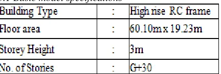
3.1 Basic model specifications
Modeling done for bare frame, frame with infill wall of various thicknesses and frame with staircase & core wall (with and without infill wall of various thicknesses) subjected to wind load.
Comparison made for Lateral displacements of frames with and without consideration of staircase &shear wall, having different thickness of infill walls.
3.2 Material Properties
The materials used for the study were Reinforced concrete with M-30 grade concrete and fe-415 grade reinforcing steel.The Stress-Strain relationship used as per IS 456:2000. The basic material properties used are as follows:
Modulus of Elasticity of steel, Es = 21,0000 MPa Ultimate strain in bending, CU =0.0035
Characteristic strength of concrete, FCK = 30 MPa Yield stress for steel, FY = 415 MPa
3.3 Modelling of Structures
Ten types of RC frames with and without Staircase and shear wall have been considered; a bare frame, a frame with External & Internal infill of 230mm & 115mm thick, a frame with external infill of 230mm thick, a frame with external infill of 150mm thick and a frame with external infill of 115mm thick. Number of storey has been G+30. The overall plan dimension of RC frame structures is 60.10m x 19.23m. All the buildings are assumed to be fixed at ground level and storey heights are taken to be 3m. A solid RCC slab of 150mm thickness has been considered and all the members of the structure are assumed to be homogeneous isotropic and having elastic modulus same in compression as well as in tension, details are shown in Table.
Loads
Following loads used for analysis Dead Load (IS 875 -part I) Live Load (IS 875 – part II) Wind Load (IS 875 –part III)
4. RESULTS AND DISCUSSION
4.1 General Consideration
Analyzed for G+30 storey structure with a 60.10m x 19.23m plan area.
Ten types of RC space frames analyzed with and without Staircase and shear wall having different thickness of Infill walls.
Considered under permanent vertical loads and Wind load (basic wind speed 50m/s). Lateral Displacements checked.
4.2 Case 1: Bare Frame
The columns are of 300mm x 1200mm size, plinth beams are of 300mm x300mm, floor & roof beams are 300 x450mm and size150mm thick Slab is considered on the all floors & Roof.
The loads acting on the structure are assigned. Here Self weight, live load, wall loads, slabs Loads and Wind loads are considered.
Case 3: Frame with Staircase and Shear Wall
The columns are of 300mm x 1200mm size, plinth beams are of 300mm x300mm, floor & roof beams are 300 x450mm and size150mm thick Slab is considered on the all floors & Roof.
The Staircase 4.20m x3.29m and shearwall 230mm thick.
The loads acting on the structure are assigned. Here self weight, live load, wall loads, slabs Loads and Wind loads are considered.
Then the structure is analyzed for linear static analysis.
5. CONCLUSION
The lateral displacement of R.C framed structure with and without considering Staircase, shear wall & infill walls was investigated using the linear static analysis. Following were the major conclusions drawn from the study.
The lateral displacement in Bare frame (RF1) is the greatest among the ten lateral load resisting systems investigated.
In all the options the values of story lateral displacements are within the permissible limits as per code limits except Bare Frame (RF1) and Frame with staircase &shearwall (RFSC1). However, it is observed that there was a considerable variation in the lateral displacement of frame with staircase & core wall while compared with bare frame.
There is a reduction in percentage of variation in later displacement of 86.45% at top storey (i.e., 93m level), when compared to bare frame (RF1) to frame with staircase, shear wall and external infill 230mm (RFSC3).
It is concluded, consideration of stiffness of different elements (i.e., staircase, shear and infill walls) in the frame analysis shows significant variation in the lateral displacement.
6. REFERENCES
[1] ASCE 7-02, “Minimum Design Loads for Buildings and Other Structures”, American Society of Civil Engineers, New York, 2002.
[2] Bungle S. Taranath, ―“wind and earthquake resistant buildings structural analysis and design”, CRC Press, Series Editor: Michael D. Meyer. Developed as a resource for practicing engineers.
[3] Dr. D.R.Panchal and Dr. S.C.Patodi, “Response of a Steel Concrete Composite Building Vis-a-Vis and R.C.C. Building under Seismic Forces”, NBM & CW journal, AUGUST 2010.
[4] IS 456:2000, “Indian Standard plain and reinforced concrete-Code of Practice”, Bureau of Indian Standards, New Delhi, 2000.