Effect of Ductility Ratio with SSI on Steel Moment Resisting
Frame Designed By Performance Based Plastic Design Method
Jaimin R. Patel, Sejal P. Dalal
Department of Civil Engineering, Sardar Vallabhbhai Patel Institute of Technology, Vasad
ABSTRACT
This paper presents, the study of seismic design considerations and design methodologies for steel moment resisting frame by performance based plastic design method considering the effect of ductility ratio with soil structure interaction (SSI). Performance-Based Plastic Design (PBPD) method has been recently evolved from the Performance based seismic design (PBSD) to achieve enhanced performance of earthquake resistant structures considering the participation of inelastic state of the material. The concept of design is mainly based on pre-selected target drift and yield mechanism as performance criteria. Performance Based Plastic design depends on “strong column-weak beam” theory, in which the pattern of failure is pre-determined. The ductility ratio of soil structure when included in PBPD method gives better approach towards the method. A brief study on effects of ductility ratio with soil structure interaction on steel moment resisting frame is presented in this paper.
Keywords : Pre-selected target drift, Yield mechanism, Ductility Ratio, steel moment resisting
frame, PBPD, soil structure interaction
I. INTRODUCTION
Design for seismic resistance has been undergoing a critical reappraisal in today’s era due to major earthquakes in the seismic regions. Code design practices have been traditionally based on the force-based design (FBD) concept in India, in which individual components of the structure are proportioned for strength on the basis of internal forces computed from the elastic analysis.
Now a days in India, steel structures are designed based on the limit state procedure as per IS 800: 2007 and IS 1893:2002 to ensure a good seismic resistant design which at times may fail in case of a severe earthquake. If a predetermined failure pattern based on “strong column weak beam” concept is used at certain points of a structure, it will assure possible inexpensive repairs even after failure of the structure.
The inelastic activity, which may include severe yielding and buckling of structure member, can be unevenly and widely distributed in the structure. This may result in rather undesirable and unpredictable response including total collapse or difficult and costly repair work at best. Therefore, societal demand are pushing the practice to achieve higher levels of performance, safety and economy, including life-cycle costs. Thus, codes are moving toward adopting performance-base design framework.
selection of a desirable yield mechanism, and structure strength and drift for given hazard levels should become part of the design process from the beginning.
One such complete design methodology, which accounts for structure inelastic behavior directly and practically eliminates the need for any assessment or iteration after initial design, such method is called Performance Base Plastic Design (PBPD). The key performance limit states applied in the PBPD method are the target drift and pre-selected yield mechanism, which are directly related to distribution and level of structural damage, respectively.
The target yielding mechanism for the steel moment frame structure is selected assuming that the plastic hinges only occur at near column of beam. The design base shear for a selected seismic hazard level is calculated by energy balance equation. A distribution of lateral design forces is used that is based on relative distribution of maximum storey shears consistent with inelastic dynamic response results.
In the past decades, many studies have been conducted on Strength reduction factor (Rμ). It
was seen that when soft soil is consider there is significant effect of strength reduction factor on it. It is also observed that SSI have significant effects
on ductility demand of structures. The SSI
provisions of seismic design code are allow designers to reduce the design base shear of building by considering soil-structure interaction as a beneficial effect. The main idea behind the provisions is that the soil-structure system can be replaced with an equivalent fixed-base model with a longer period and usually a larger damping ratio. Researchers concluded that SSI reduces the Rμ values, especially for the case of buildings
located on soft soils, which can predict and give results on seismic design forces [9].
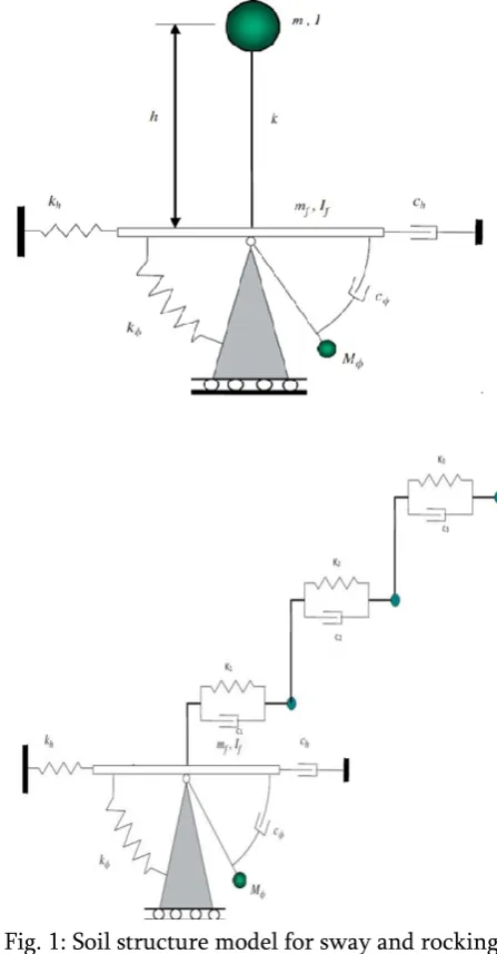
Fig. 1: Soil structure model for sway and rocking motion for SDOF and MDOF systems.
II. METHODOLOGY
moments is also calculated as per suggestions given by Chao, 2006.
III. LATERAL FORCES AND VERTICAL
DISTRIBUTION
For various loading classes specified in IS 875, design seismic force shall be estimated using full dead load plus percentage of imposed load as given in table 7 of IS 1893-2016. The seismic weight of each floor is calculated by appropriately splitting the weight of columns and walls in any story to the floors above and below the story. The seismic weight of the building is the sum of seismic weight of all floors.
Fundamental Natural Time Period (T) for RC frame can be calculated as per IS-1893-2016 clause 7.6.2(c).
T = 0.085 h0.75
Where,
h = height of structure (in m)
Step: 1 Select a desired Target Yield Mechanism for design earthquake hazard. Figure shows the design yield mechanism of moment resisting frame subjected to lateral force and pushed through the design target plastic drift, “Δp”.
Fig. 2: Pre-Selected Yield Mechanism of Moment Frame with Beam Plastic Hinges away from
Column Faces
Step: 2 Calculation of shear distribution factor “βi”
of each floor. [4]
βi = =
Where,
βi = Shear distribution factor at level i ,
Vi = Story shear force at level i,
Vn = Story shear force at roof level (nth
level),
wj = Seismic weight at level j ,
hj = Height of level j from base,
wn = Seismic weight at the top level,
hn = Height of roof level from base ,
T = Fundamental time period.
Step: 3 Calculation of Ah (Dimensionless
parameter) can be carried out by following formula
Ah = ( ). .
Where,
θp = Global inelastic drift ratio of the
= θu - θy ,
θu = Target drift Ratio,
θy = Yield drift Ratio,
βi= Shear distribution factor at level i ,
g = Gravitational Acceleration
Step: 4 Calculation of Story shear “Vb” [2]
Vb = )* W
Where, ϒ =
Sa, inelastic =
Where,
Vb = Base shear force,
γ = Energy modification factor,
μs = Structural ductility Factor = θu / θy ,
θu = Target drift Ratio ,
θy = Yield drift Ratio ,
Rμ = Ductility Reduction factor,
Sa,inelastic = Spectral acceleration due to
inelastic response, Vb = total story shear at base,
W = Total design Seismic Load.
Rμis related to time period of structure and can be
obtained by using inelastic spectra [8].
Rμ = ai T bi
Where,
T = Fundamental period of the
corresponding fixed-base structure, ai & bi = Constant coefficient, which depend
on ductility ratio, aspect ratio, number story and equivalent frequency.
Step: 5 Calculation of the Design Lateral force “Qn” of Roof Floor.
Qn =
Where,
Qn = Lateral Force at nth level (roof level)
Step: 6 Calculation of the Design Lateral force “Qi” of each level.
Qi = Qn
Where,
Qi =Lateral Force at ith level
IV.ANALYSIS OF BEAMS
Step: 1 Calculation of required plastic moment of column (Mpc)
=
Where,
V’ =
h1 = Height of the first story
Step: 2 Calculation of required moment strength of beam (Mpb)
=
Where,
Qi = Lateral Force at ith level,
hi = Height at ith level,
Mpc = Required plastic moment of column,
βi = Shear distribution factor at level i ,
L = Distance between two column, Li’= Distance between centre of RBS cuts.
V. DESIGN OF BEAMS
IS-800:2007 (clause 8.2 for flexure and clause 8.4 for shear and checked for deflection as per clause 5.6.1.) and Reduced Beam Section is consider as per ANSI/AISC 358-05.
Fig. 3: Reduced Beam Section
0.5bbf a 0.75bbf
0.65d b 0.85d
0.1bbf c 0.25bbf
Where,
bbf = Width of beam flange,
d = Depth of beam section,
a = Distance of cut at the face of column to start of RBS cut,
b = Length of RBS cut,
c = Depth of cut at centre of reduced beam section,
Sh = Distance from a column face to the
centre of RBS cut = a + b/2
Step: 2 Calculation of plastic section modulus at the centre of RBS (Ze).
Ze = Z – 2ctbf ( d – tbf )
Where,
Ze = Plastic section modulus at centre of the
reduced beam section,
Z = Plastic section modulus for full beam cross-section
Step: 3 Calculation of the probable maximum moment (Mpr) at the centre of RBS.
Mpr = Cpr Ry Fy Ze
Where,
Cpr = Factor of peak connection strength
= 1.0 for roof beam = 1.075 for other beam
Ry = 1.1, which is ratio of expected yield
stress to specified min. yield stress
Step: 4 Calculation of shear force at the centre of RBS.
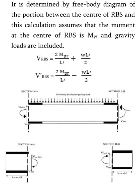
It is determined by free-body diagram of the portion between the centre of RBS and this calculation assumes that the moment at the centre of RBS is Mpr and gravity
loads are included.
VRBS =
V’RBS =
Fig. 4: Free-Body Diagram between Centre of RBS and Face of Column
Step: 5 Calculate the probable maximum moment at the face of the column.
Mf = Mpr + VRBS Sh
VI.ANALYSIS OF COLUMN
Step: 1 Calculation the sum of lateral forces (FL)
for Exterior Column Tree.
FL =
Where,
Mpr = Probable maximum moment at the
centre of RBS,
VRBS = Shear force at the centre of RBS,
Sh = Distance from a column face to the
centre of RBS cut = a + b/2, dc = Depth of the column ,
Mpc = Required plastic moment of column
= When i = n, = 0
Step: 2 Calculation the sum of lateral forces (FL)
for Interior Column Tree.
FL =
Where,
Mpr = Probable maximum moment at the
centre of RBS,
VRBS, V’RBS = Shear force at the centre of RBS,
Sh = Distance from a column face to the
centre of RBS cut = a + b/2, dc = Depth of the column ,
Mpc = Required plastic moment of column
= When i = n, =
0
Fig.5: Free-body Diagram of Exterior Column Tree and Interior Column Tree
Step: 3 Calculation of Total axial Force on a column section (N)
N = OR
N =
Where,
(Pc)i = Axial force on column section
Step: 4 Calculation of Total bending moment on column section (M)
M= ( + )( ) + +
VII.DESIGN OF COLUMN
After getting the proper design bending moments, shear force and axial force for columns by Free-body diagram, the columns are designed for bending moment as per clause 7.1 of IS 800:2007.
VIII. SUMMARY
PBPD method, it is important to note that drift control and yielding are taken into account in the beginning itself, so there is no need for lengthy iterative process to arrive at the final design results. Also the proper research has not been done in the direction of considering soil structure interaction in PBPD method, so more research in this direction is considered. New distribution of lateral design forces is used which is based on relative distribution of maximum story shears consistent with inelastic dynamic response results. If analysis is done by PBPD method considering Soil Structure Interaction gives accurate results. Because PBPD method directly accounts for structural inelastic behavior. SSI reduces the Strength reduction factor (Rμ) values, especially
for the case of buildings located on soft soils.
IX. REFERENCES
[1].
H Akiyama, “Earthquake resistant limitstate design for cylindrical liquid storage tanks”, Earthquake Engineering, 10th World
Conference, 1992.
[2].
Sutat Leelataviwat, Subhash C Goel andBozidar Stojadinovic, “Towards
performance-based seismic design of
structure”, Dept of Civil and Env engg., University of Michigan, Earthquake Spectra,
August 1999.
[3].
Soon-Sik-Lee, Subhash C Goel andShih-Ho-Chao, “Performance-based seismic
design of steel moment frames using target drift and yield mechanism”, 13th World
Conference on Earthquake Engineering,
Paper No. 266, August 1 2004.
[4].
Shih-Ho Chao, Subhash C Goel andSoon-Sik Lee, “A seismic design lateral force distribution based on inelastic state of
structure”, Earthquake Engineering
Research Institute, Aug 2007.
[5].
Subhash C Goel, Wen-Cheng Lio, M.RezaBayat and Shih-Ho Chao, “Performance-based plastic design (pbpd) method for
earthquake-resistant structures: an
overview”, The Structural Design of Tall
and Special Builing., Vol. 21, Oct 2009.
[6].
Subhash C Goel, Shih-Ho Chao, SutatLeelataviwat and Soon-Sik Lee,
“Performa'ce-based plastic design (pbpd) method for earthquake-resistant structures”,
14th World Conference on Earthquake
Engineering, Oct 2008.
[7].
Tomaz Vidic, Peter fajfar and Matejfischinger, “Consistent inelastic design spectra: strength and displacements”, Dept of Civil engg., University of Lgubljana, ”,
Earthquake Engineering and structural
dynamics,1994
[8].
Behnoud Ganjavi* and Hong HaoIn“Strength reduction factor for MDOF soil– structure systems” the structural design of tall and special buildings Struct. Design Tall Spec. Build. (2012) Published online in
Wiley Online Library
(wileyonlinelibrary.com/journal/tal). DOI: 10.1002/tal.1022