The Structural Behaviour of Aluminosilicate
Frameworks at High Pressures and Temperatures.
Timothy Patrick Hackwell
Department of Geological Sciences, University College London.
Submitted for the degree of Doctor of Philosophy, University of London.
ProQuest Number: 1 0 0 4 5 6 9 7
All rights reserved
INFORMATION TO ALL U S E R S
The quality of this reproduction is d e p en d en t upon the quality of the copy submitted.
In the unlikely event that the author did not se n d a complete manuscript
and there are missing p a g e s , t h e s e will be noted. Also, if material had to be removed, a note will indicate the deletion.
uest.
ProQuest 1 0 0 4 5 6 9 7
Published by ProQuest LLC(2016). Copyright of the Dissertation is held by the Author.
All rights reserved.
This work is protected against unauthorized copying under Title 17, United States Code. Microform Edition © ProQuest LLC.
ProQuest LLC
789 East Eisenhower Parkway P.O. Box 1346
Dedicated to
"Whenever a thing changes and alters its nature^
at that moment comes the death o f what it was before."
Abstract.
Framework silicates are the most abundant constituents of the Earth’s crust and upper mantle. Feldspars are quantitatively the most important of the rock-forming silicates, making up to 60% of the Earth’s crust. In order to understand the complex igneous and metamorphic processes which take place within the earth it is vital that we understand the response of major rock-forming minerals, such as feldspars, to pressure and temperature.
The crystal structures of feldspars are reviewed, starting with the ideal formula, MT^Og. The topology of the structure is then discussed, followed by the perturbation to the structure caused by the M cation and distribution of the T atoms. This is followed by an introduction to Landau theory, and the means by which a phase transition in a material can be approached macroscopically.
The last twenty-five years has seen rapid and widespread development of DACs suitable for single crystal X-ray diffraction experiments. The various types of DACs are reviewed and the relative advantages and disadvantages of each cell discussed. This is followed by a description of the construction and operation of each cell. The second half of this chapter concentrates on the development of a new DAG suitable for use at high pressure and temperature. Again the construction and operation of the cell is described.
parameters, and principal strain directions at high pressure, allow a number of conclusions to be made on the structural response of feldspars to high pressure.
The P I-II phase transition in end-member anorthite has been reversed in-situ at high pressures and temperatures, using a single crystal sample and an externally heated DAC. At high pressures the phase boundary is linear and nearly isobaric, and marked by a first order step in volume. At high temperatures the boundary is linear and isothermal and there is no detectable discontinuities in unit-cell parameters.
Acknowledgements.
I would like thank Michael Carpenter (Cambridge), Alan Hart (NHM) and Paul Pohwat (USNM) for providing some of the samples used in this study.
Within the Crystallography and Mineral Physics group at U (X I am especially indebted to my supervisor Ross Angel. I would also like to thank David Price, Ian Wood, Nancy Ross and Pete Woods for their support (technical and otherwise). During my time at UCL I’ve been involved in a number of unhealthy discussions concerning life, the universe and everything (including feldspars). For these insights and other things I’d like to shout the praises of the "luscious" Lidunka and Atul.
My parents have shown unstinting loyalty to a layabout such as myself, for this I am forever in their debt. I’d also like to thank my friends Simon and Karen who’ve been a couple of swells.
Contents.
Abstract
Acknowledgements
Chapter 1: Introduction. 18
1.1 Introduction 18
1.2 The Occurrence of Feldspars 19
1.3 Approach and Organisation of Thesis 24
Chapter 2: Feldspar Crystal Chemistry. 26
2.1 Introduction 26
2.2 Topology of the Aluminosilicate Framework 27
2.3 The M Cation Environment 33
2.4 Aluminium-Silicon Distribution 41
2.5 The Landau Theory of Phase Transitions 46
25.1 Introduction 46
2 5 2 The Order Parameter 46
2 5 .3 Landau Free Energy Expansions 49
2 5 .4 The Effect o f Pressure on Landau Free Energy Expansions 56
2 5 5 The Coupling o f Q with Spontaneous Strain and Composition 59
2 5 .6 Phase Transitions and Order Parameter Coupling 63
2.6 Summary 63
Chapter 3: Experimental Techniques. 66
3.1 High Pressure Experimental Techniques 6 6
3.1.1 Introduction 6 6
3.1.4 Pressure Measurement 84
3 .1 5 X-Ray Diffraction Experiments 88
3.1.6 Data Refinement 91
3.2 High Pressure-Temperature Experimental Techniques 91
3.2.1 The High Pressure-Temperature Diamond Anvil Cell 91
3.22 Operating the High Pressure-Temperature Diamond Anvil Cell 99
3 .2 3 Pressure Calibration 104
3.2.4 X-Ray Diffraction Experiments 105
Chapter 4: The Comparative Compressibility of Feldspars. 107
4.1 The Bulk Moduli of Feldspars 107
4.1.1 Introduction 107
4.1 2 The Bulk Moduli o f Boron Feldspars 117
4.1.3 The Effect o f Composition on the Bulk Modulus 123
4.1.4 The Effect o f Disorder at Constant Composition
on the Bulk Modulus 132
4 .1 3 The Effect o f Changing Framework Configuration at Constant
Composition and Order on the Bulk Modulus 135
4.2 The Variation of Unit-Cell Parameters With Pressure 138
4.3 The Variation of Strain Tensors With Pressure 145
4.4 Conclusions 153
Chapter 5: The Behaviour of Anorthite at High Pressures
and Temperatures. 155
5.1 Introduction 155
5.6 The Application of Landau Theory 181 5.7 The Atomistic Mechanism of the P l-Il Phase Transition 193
5.8 Conclusions 197
Chapter 6: Transformations in Alkali Feldspars at High Pressures. 199
6 .1 Introduction 199
6.2 The Behaviour of Sanidine at High Pressures 201
6.2.1 Introduction 201
6 .2 2 Experimental Details 209
6 .2 3 Discussion 209
6.3 The Behaviour of Microcline at High Pressures 215
6.3.1 Introduction 215
6.3 2 Experimental Details 217
6.3 2 Discussion 221
6.4 Conclusions 234
Chapter 7: Conclusions. 236
References 240
List of Figures.
C h ap ter 1: Introduction.
1.1 Feldspar An-Ab-Or ternary diagram for minerals quenched
from high temperature 2 0
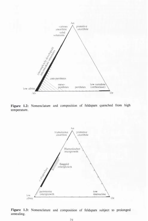
1.2 Nomenclature and composition of feldspars quenched from
high temperature 2 1
1.3: Nomenclature and composition of feldspars subject to
prolonged annealing 2 1
C hapter 2: Feldspar Crystal Chemistry.
2.1 Perspective drawing of the double crankshaft chain in feldspars 28 2.2 Projection down the a-axis of the crankshaft chain in feldspars 28 2.3 Nature of the sheets of tetrahedra lying perpendicular to the
double-crankshaft chains in feldspars 29
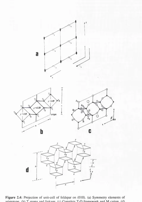
2.4 Projection of unit-cell of feldspar on (010) 31
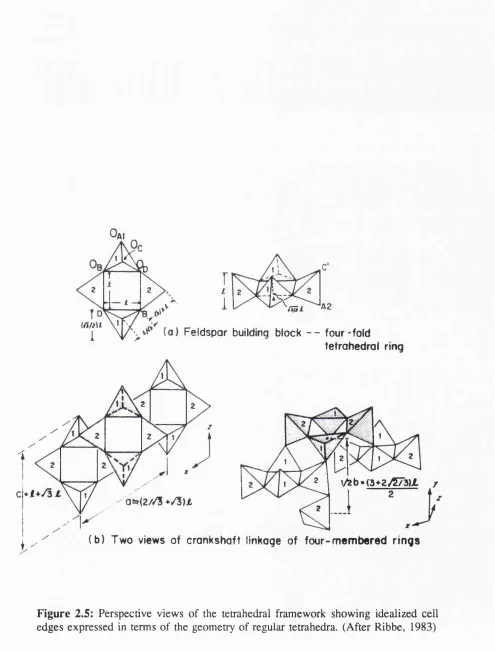
2.5 Perspective views of the tetrahedral framework showing idealized cell
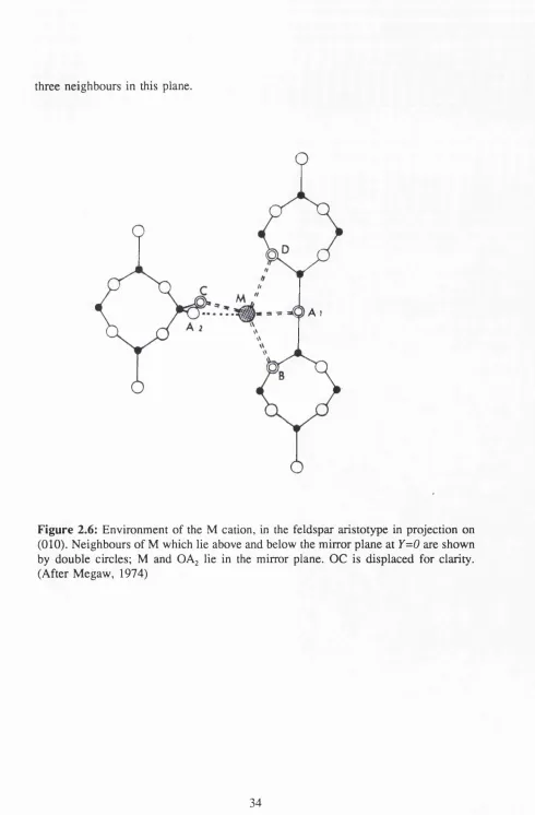
edges expressed in terms of the geometry of regular tetrahedra 32 2.6 Environment of the M cation, in the feldspar aristotype in
projection on (010) 34
2.7 The environment and bonding of K atoms in high sanidine 36 2.8 The engineering model of feldspar; a projection down 6 of a
slab bounded by y=±0.3 38
2.9 The engineering model of feldspar; skeletal diagram with T and O atoms
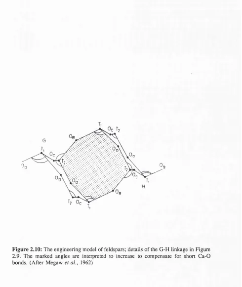
as small dots, and showing how the slabs are linked to form a framework 39 2.10 The engineering model of feldspars; details of the G-H linkage
in Figure 2.9 40
2.11 Schematic diagram of linkage pattern of tetrahedra projected on (010) 43
Chapter 3: Experimental Techniques.
3.1 Basic geometry of the diamond anvil cell 6 8
3.2 Sectional view of the National Bureau of Standards
ultrahigh-pressure DAC 70
3.3 Pneumatic pressure cell of Fourme 71
3.4 Exploded view of the miniature DAC of Merrill and Bassett 73
3.5 Sectional view of the DXR-4 DAC 74
3.6 Single crystal diamond anvil cell developed by Keller and Holzapfel 76
3.7 Diamond anvil cell of Schiferl 78
3.8 Cross section of the Malinowski transverse geometry DAC 80
3.9 Exploded of Mao and Bell cryogenically loaded DAC 81
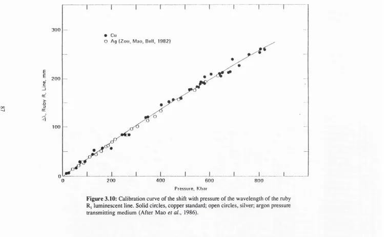
3.10 Calibration curve of the shift with pressure of the
wavelength of the ruby Rj luminescent line 87
3.11 Exploded view of high-pressure high-temperature DAC developed
by Hazen and Finger 93
3.12 Sectional view of the heating cradle developed to carry out
high P-T experiments 96
3.13 Photograph of modified diamond anvil cell fitted to the heating cradle 97 3.14 Photograph of modified diamond anvil cell and heating cradle
on the 4-circle diffractometer 98
3.15 Sample temperature within the diamond anvil cell as a function
of heater power 1 0 1
Chapter 4: The Comparative Compressibility of Feldspars.
4.1 Variation with pressure of the volume of a selection of feldspars
determined by piston-cylinder techniques 1 1 0
4.2 Environment of the M cation, in the feldspar aristotype
in projection on (0 1 0 ) 116
albite and anorthite 1 2 1
4.4 Variation with composition of the bulk moduli of plagioclase feldspars 129 4.5 Fourier sections of the scattering density at the Ca sites in anorthite 137 4.6 Plots of the unit-cell parameters, b against c for five feldspars 140
4.7 Deformation of an extendible string 144
4.8 Orientation of the principal strain axes of the strain ellipsoids
for A) sanidine OrçgAbj; B) sanidine GrgjAbig 149
4.9 Orientation of the principal strain axes of the strain ellipsoids
for A) amazonite microcline Org^; B) Norwegian microcline Orgg 150 4.10 Orientation of the principal strain axes of the strain ellipsoids
for A) albite Ab^gAn^Or^; B) reedmergnerite 151
4.11 Orientation of the principal strain axes of the strain ellipsoids for
A) anorthite Anjoo (QoD=0.92); B) anorthite Anjoo (Qod=0-78); C) An^yAb^g 152
Chapter 5: The Behaviour of Anorthite at High Pressures and Temperatures.
5.1 Diagram to illustrate the soft phonon theory for the anorthite
P l-Il phase transition 161
5.2 Comparison of the variation of anorthite unit-cell parameters with temperature across the P l-Il phase transition for a crystal inside the high
P-T cell, and earlier X-ray diffraction studies at high temperatures 167-168 5.3 Phase diagram for the P l-Il phase transition in anorthite at
high pressures and temperatures 175
5.4 Variation of the unit-cell angles of anorthite with pressure
and temperature 176
5.5 Variation of scaler spontaneous strain at the P l-Il transition
in anorthite 177
5.6 Diagrams to illustrate the change in intensities of the c-reflections
across the P l-Il phase boundary in anorthite 179
across the P I-11 phase boundary in anorthite 180 5.8 Variation of G with Q for distinctive geometries of the
free energy quaitic 189
5.9 Variation of dGldQ with Q for the configurations in Figure 5.7 190 5.10 Projection of the structure of primitive anorthite onto the ac plane 194 5.11 Schematic diagram of the possible behaviour of the calcium atoms
in anorthite, at non-ambient conditions 196
Chapter 6: Transformations in Alkali Feldspars at High Pressures.
6.1 Phase boundary of the diffusive high albite to monalbite transformation,
and the displacive analbite to monalbite transformation 2 00
6.2 Monoclinic to triclinic transition surface for disordered
alkali feldspars 203
6.3 Schematic diagram to illustrate the possible positions of the C2/m-Cl
phase transition for disordered alkali feldspars in T-X space 205 6.4 Variation of sanidine unit-cell edges with pressure 207
6.5 Variation of the sanidine p angle with pressure 208
6 . 6 Variation of sanidine unit-cell volume with pressure 208
6.7 X-ray diffraction peak profiles in a hydrostatic and non-hydrostatic
pressure medium 21 2
6 . 8 Schematic phase diagrams showing the CUm to C l phase in:
A) T-X space; B) P-X space 214
6.9 Variation of amazonite microcline unit-cell edges with pressure 222 6.10 Variation of amazonite microcline unit-cell angles with pressure 223 6.11 Variation of amazonite and Norwegian microcline unit-cell volume
with pressure 224
6.15 Infrared absorption spectra of amazonite microcline at high pressures,
in the 850-700 cm^ region of the spectra 231
6.16 Infrared absorption spectra of amazonite microcline at high pressures,
List of Tables.
Chapter 3: Experimental Techniques.
3.1 Power-temperature characteristics of the modified high P-T diamond
anvil cell and heating cradle 1 0 2
3.2 Temperature characteristics of the modified high P-T diamond
anvil cell and heating cradle 103
Chapter 4: The Comparative Compressibility of Feldspars.
4.1 Bulk moduli determinations by press techniques 109
4.2 Bulk moduli determinations by ultrasonic techniques 113 4.3 Variation of anorthite compressibility K (in GPa) with changing K ’ 115
4.4 Unit-cell parameters of danburite at pressure 119
4.5 Unit-cell parameters of reedmergnerite at pressure 120
4.6 Bulk moduli of plagioclase feldspars determined by X-ray diffraction 125
4.7 Unit-cell parameters of anorthite at pressure 127
4.8 Unit-cell parameters of sample 97490/1 (An^yAb^^) at pressure 128 4.9 Bulk moduli of alkali feldspars determined by X-ray diffraction 131 4.10 Bulk moduli of Val Pasmeda anorthite with various values of Qoo 134 4.11 Unit-cell parameters of amazonite microcline at pressure 141
4.12 Unit-cell parameters of Eifel sanidine at pressure 142
Chapter 5: The Behaviour of Anorthite at High Pressures and Temperatures.
5.1 Unit-cell parameters of the anorthite PI and II phases at high
pressures and temperatures 172-173
Chapter 6: Transformations in Alkali Feldspars at High Pressures.
6.2 Electron microprobe analysis results for the amazonite and
Norwegian microcline 217
6.3 Unit-cell parameters of amazonite microcline at pressure 219 6.4 Unit-cell parameters of Norwegian microcline at pressure 220 6.5 Re-analysis of the unit-cell parameters of a second amazonite
1. Introduction.
1.1 Introduction.
Silicates are the largest group of compounds occurring in the Earth’s crust. Feldspars are the most important single group of rock-forming silicate minerals, and make up approximately 60% of the Earth’s crust. The majority of feldspar minerals have aluminosilicate framework structures with interstices occupied by alkali or alkali-earth atoms. Feldspars are the major constituents of acid, alkaline, intermediate and basic igneous rocks, and are only absent from ultrabasic or rare alkaline rocks. They are important constituents of schists and gneisses, and occur in many regionally metamorphosed rocks. They are frequently found as authigenic crystals or detrital grains in arenaceous rocks, and it is not uncommon to find them in mineral veins.
1.2 The Occurrence of Feldspars.
The aluminosilicate structure is composed of comer-sharing SiO^ and AIO4 tetrahedra,
linked in an infinite three dimensional array. Charge balancing "M" cations occupy large cavities within the tetrahedral framework. The majority of feldspars can be classified chemically as members of ternary system NaAlSijOg-KAlSijOg-CaAljSijOg. Members of the series between NaAlSi^Og and KAlSijOg are called alkali feldspars. Members of the series between NaAlSijOg and CaAljSijOg are called plagioclase feldspars (Figure 1.1).
Figure 1.2 represents the relations typical of feldspars which have had short cooling histories. Homogeneous feldspars occupy small areas. Most alkali feldspars are perthites, consisting dominantly of an alkali feldspar host with exsolved plagioclase phase. When plagioclase feldspars are dominant the unmixed feldspar is called an antiperthite. If there are equal amounts of K-feldspar and plagioclase, these are called mesoperthites.
CoAI^SizOe (An)
Ana no rthite
high bytownite
high ^ labradorite
Two f e l d s p a r s high
a n d e s i n e
high o lig o c la s e
K-high albite m o n a lb ite ) ( N a ) - h i g h / — —
albite /
NoAISiaOg (Ah)
K - s a n i d i n e N a - . . .
s a n id in e
ALKALI
FELD SPA RS
An
p r i m i t i v e a n o r t h i t e v a r i o u s
a n o r t h i t e
s o l i d s o l u t i o n s /
a n t i - p e r t h i t e s
l o w s a n i d i n e p e r t h i t e s ( o r t h o c l a s e ) m e s o
p e r t h i t e s l o w a l b i t e
O r
Ab
Figure 1.2: Nomenclature and composition of feldspars quenched from high temperature.
An
t r a n s i t i o n a l a n o r t h i t e
p r i m i t i v e a n o r t h i t e
H u t t e n l o c h e r i n t e r a r o w t h
B o g g i l d i n t e r g m w t h
l o w m i c r o c l i n e p e r i s t e r i t e
i n t e r g r o w t h
l o w
a l b i t e O r
The sodium-potassium feldspars are essential constituents of acid and acid-igneous rocks. They are abundant in granites, syenites and their volcanic equivalents, while alkali feldspars are major constituents in pegmatites and acid gneisses. In plutonic rocks the alkali feldspars are usually orthoclase and microcline compositions, and perthite and microperthite textures. In volcanic rocks the alkali minerals are sanidine, sanidine perthite and anorthoclase crytoperthite. Potassium rich feldspar minerals also form during the hydrothermal stage of crystallization of granitic rocks. These minerals are formed as a by-product of the transformation of biotite to chlorite. The transformation is represented by the reactions:
K2M g5A l4S i5 0 2o ( O H)4 + 4 S i O z + ^ M g jA l^ S ia O io C O H )» + I K A l S i ^ O ,
eastonite
2 KFe3^"AlSi3 0 ,o(OH) 2 + Fe5+2 Fe^'AlSi3 0 ,o(OH)g + KAlSi3 0 g + K+
annite
Potassium feldspar is a stable product of both high grade thermal and regional metamorphism. It occurs in a variety of thermally metamorphosed sediments including: shales, impure limestones, and impure sandstones. It is the typical mineral of the sillimanite zone of regional metamorphism. The formation of alkali feldspar minerals in high grade metamorphic zones is mainly due to the instablity of micas at high pressures and temperatures, i.e.:
K (M g,Fe)3A lSi30io(O H )2 + SSiO^ ^ K A lSi3 0g + 3 (M g ,F e)S i0 3 + H^O biotite
K A l3S i3 0 io(O H )2 + S iO z K A lS i3 0 g + A ljS iO j + H^O
KAl3Si3 0 ,o(OH) 2 + CaC0 3 + ZSiO^ KAlSi3 0 g + CoAl^SigOg + H^O + CO^
muscovite
K-feldspars can also crystallize during the formation of sedimentary rocks. They are commonly found in siltstone, sandstones and shales. Crystallization occurs at the same time as sedimentation, or by later replacement.
Plagioclase feldspars are the most abundant mineral group in many basalts. They occur both as ground mass and phenocrysts. Albite is the most common mineral in spilites. In many spilites it is common to find relict labradorite or andesine enclosed within albite. This relationship is considered evidence that the present composition is a result of a late magmatic metasomatic process in which the original rocks have been albitized to form spilites. In this reaction the formation of albite from plagioclase takes place without appreciable volume change. This reaction can be represented by:
CaNaAljSijOie + Na+ + - 4 2NaAlSi3 0 g + Ca+" + AP"
In other spilites there is no textural evidence that albite is not a product of normal magmatic processes, and formed from residual igneous fluids derived from olivine basalts or tholeiitic basalt. Plagioclase minerals are the most abundant constituents of plutonic rocks. Feldspars of the calc-alkaline rock series include almost the whole range of plagioclase feldspars. The plagioclase minerals in pegmatites are generally albite, while those in anorthosites vary widely in composition. When metamorphic rocks of the amphibolite facies are subject to further increases in pressure and temperature, the granulite facies is reached and anorthite is formed:
When rocks of the amphibolite facies are effected by increasing temperature and decreasing pressure, the rocks enter the pyroxene homfels facies. Pyroxene is unstable in this facies and breaks down to form plagioclase. This is expressed by the equation:
NaCa2Mg3Fe^^Al3Si6022(0H)2 + 4 S i0 2 N aA lS i3 0 , + CaAl2Si20g + CaM gSi20ô +
amphibole Mg2FeSi3 0 g + H2O
Plagioclase is also an important product of the thermal metamorphism of impure limestone. The plagioclase of thermally metamorphosed impure arenaceous sediments form from the recrystallization of detrital feldspars. Calcium plagioclase also occurs in some stony meteorites.
4.3 Approach and Organisation of Thesis.
Chapter 4 describes a number of high pressure, single crystal, X-ray diffraction experiments, carried out to determine to the compressibility of a selection of feldspars. Analysis of the unit-cell data from the experiments, and the use of previously published unit-cell data, allowed the Mumaghan equation of state to be fitted to the volume pressure data, and a bulk modulus obtained for each crystal structure. This is supplemented by a comparison of the unit-cell parameter, and strain tensor changes with pressure. Chapter 5 describes how the PI-II phase transition in anorthite was reversed in situ at high pressures and temperatures. In Chapter 6 the high pressure,
2. Feldspar Crystal Chemistry.
2.1 Introduction.
The crystal structure of feldspars are composed of an aluminosilicate framework whose interstices are occupied by alkali and alkali-earth atoms. The general composition is given by MT^Og, where T stands for atoms capable of tetrahedral coordination with oxygen (usually A1 or Si, but also B, F e^ and others). Each quadruply-charged silicon atom balances electrostatically the four half oxygens in its tetrahedron, but each aluminium centred tetrahedron is unbalanced by one charge. Charge balance is maintained by the introduction of large metal atoms (M) into the interstices. The structure is composed of a linkage scheme in which the AIO4 and SiO^
tetrahedra share comers in a 3-D continuous framework (Machatschki, 1928).
2.2 Topology of the Aluminosilicate Framework.
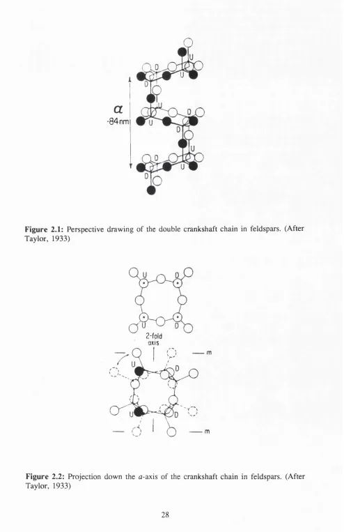
Taylor (1933) was the first to envisage the actual topology of framework structures. Taylor noted that, by use of pseudo-tetragonal axes [100], [010] and [102], the feldspar lattice could be divided into boxes separated by mirror planes and pairs of two-fold rotation axes. Taylor found only one way in which the four key structural tetrahedral units could fit into the box whilst obeying the symmetry and having reasonable bond lengths. The four-membered rings of TO4 tetrahedra, when comer-
shared with similar rings, form double crankshaft chains parallel to the fl-axis (Figure 2.1). From Figure 2.1 it can be seen that there are two types of four membered rings in the chain, one normal to the 6 -axis and the other approximately normal to the a-
axis.
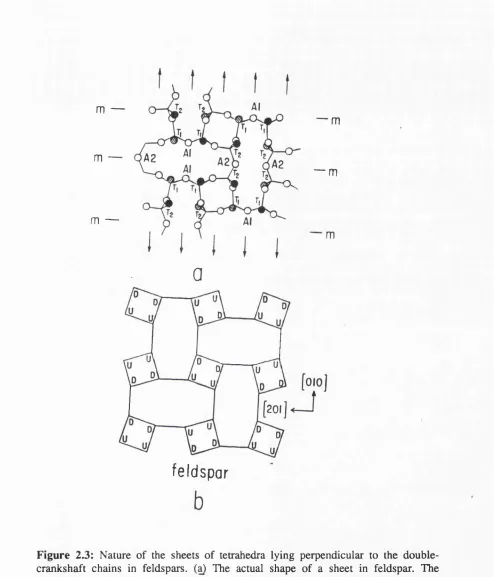
When viewed down the a-axis a four membered ring consists of two pairs of non- equivalent Ti and Tj tetrahedra, one T^-Tg pair with apices pointing upwards and the other with apices pointing downwards (Figure 2.2). Figure 2.3a shows the actual shape of a sheet in feldspars. The projection was made onto the (201) plane deHned by the [010] and [102] zone axes using the oblique a-axis for projection. Each double crankshaft is represented by a four membered ring composed of two tetrahedra of type Ti and two of type T2 shown at the intersection of lines. The solid and hatched circles
a
■84 nm
Figure 2.1: Perspective drawing of the double crankshaft chain in feldspars. (After Taylor, 1933)
2-fold axis
c r
m
m
m —
m —
m —
— m
•— m
m
feldspar
Megaw (1974) constructed a conceptually simple diagram for the structure orientated normal to the 6-axis (Figure 2.4). Figure 2.4a shows the symmetry elements of C2/m in the feldspar unit cell. There are mirror planes parallel to the paper and a rotation diad axis perpendicular to them, intersecting the planes in centres of symmetry, one of which is taken as the origin. The unit cell contains four formula units of MT^O,. The general position of symmetry-equivalent atoms in space group C2/m is 8-fold. Figure 2.4b shows a projection of the unit cell onto the (010) plane. The origin of the coordinates is in the lower right hand comer of the cell. Tj atoms are inserted at x=0, z=0.25 and the position derived from this by the rotation diad, x=0, z=0.75. These are at a height of y-0.15. The four membered ring is repeated at the opposite end of the cell by the a-translation vector. When oxygen atoms are added (Figure 2.4c), the partial projection shows that the Og and Oq atoms are on the sides of the horizontal four ring, Oq is on the side shared with the vertical four ring. Oc is on the vertical side of the vertical four ring, which is centrosymmetric. 0^(2) is on the mirror plane, near the T2-T2 join, and 0^(1) on the diad axis, on the projection of the Tj-Tj join.
The M cation lies on the mirror plane at y=0, lying on the straight line between 0^(2) and the 0^(1) of alternate four rings. The 0^(1) is at a height y-0.15, below it is the mirror plane containing 0^(2) and M. Figure 2.4d is a perspective diagram showing the "crankshafts" reflected by (010) mirror planes at y=0.25, 0.75. Solid lines join T atoms, Oa(2) atoms lie on dotted lines joining one crankshaft to its mirror image, and 0^(1) oxygens are represented by circles.
a
X
origin
à
Feldspar building block - - four-fold
tetrahedral ring
1/26. (3^2/573)1 /
(b) Two views of crankshaft linkage of four-m em bered rin gs
If a similar four-ring is turned upside down and adjusted until the two lower vertices coincide with the two upper vertices of the first ring, a secondary four ring is formed. Repetition of this operation forms the crankshaft (Figure 2.5b). The model described here is a very simplified one and a number of possible modifications in actual feldspar structures must be noted:
1) The orientation of the tetrahedra may not be as perfect as shown in the diagrams.
2) The tetrahedra are not always the same size as a result of either containing different atoms, or the oxygens atoms having a variety of bonding environments.
3) The Tetrahedra are not always regular in shape. Regularity is judged by 0 - 0 edge lengths, or by T-O bond lengths and O-T-O bond angles.
2 3 The M Cation Environment.
three neighbours in this plane.
« A I
The idea of comparing an aluminosilicate framework to an engineering structure was first proposed by Megaw et al. (1962) to explain the geometrical features of the structure of anorthite and other feldspars. Entrance of large M cations into the interstices involves only a small deformation of the aluminosilicate framework, whilst the introduction of small atoms involves a large deformation. The effective ionic radii (taken from Shannon and Prewitt, (1969) radii for eight coordination) of a number of cations are as follows:
K:1.51A Na;1.16Â
Ba:1.42Â Ca;1.12Â
Sr:1.25Â Rb:1.60Â
m
asin/8
d
122
shared
126
m
Figure 2.7: The environment and bonding of K atoms in high sanidine, as seen in projection down the c-axis. The heights of atoms are given in percentage of c. The potassium-oxygen bonds are shown by dashes. The heavy dashes showing the shortest distances to A2 and A, oxygens. Oxygen edges shared between polyhedra are shown
The engineering model by developed by Megaw et al. (1962) has been of great use in developing the understanding of the complex aluminosilicate framework geometry. Figures 2.8 and 2.9 are stylized diagrams of part of the anorthite structure. The 6-axis projection (Figure 2.8) includes all atoms except Oc, and shows the pseudosymmetry which exists within a (010) slab of the structure bounded approximately by y= ±0.3. To this approximation, atoms Og and O^ are equivalent, and symmetry is orthorhombic, atoms Ca, 0^(1) and 0^(2) each lying at the intersection of two mirror planes. The slab is built from a double sheet of T-O tetrahedra, each sheet containing four-membered rings bound tightly to rings in the other sheet by a complex system of cross-girders emanating from Ca and 0^(2). Figure 2.9 shows the linkage between one slab and the next, between the upper rings of the slab in Figure 2.8 (centred on y=0) and the lower rings of the one above it (centred on y=0.5). The linkage is through Oc- The orthorhombic pseudosymmetry has disappeared. Atoms O^ are topologically distinguished from Og by their participation in a four membered ring with Oc, which stands in a vertical plane linking the layers. The repeat distance in the
X* direction is determined by two different links, represented in Figure 2.8 and 2.9 by heavily drawn lines E-(F,F’) and G-H respectively. For equilibrium the engineering approach of Megaw et al. (1962) requires that the stresses in E-(F,F’) and G-H must be equal and opposite. However, the shortness of the Ca-OA(2) bond must mean that E-(F-F’) is in compression and hence G-H must be in tension. Megaw et al. (1962) assumed that the tension would affect bond angles rather than bond lengths. Negative strains are expected in the angles shown in Figure 2.10, whilst negative strains are expected in T2(BD) and T2(AC), the latter rotating the bond TyC^ downwards towards
Ca 0 ,(1) Ca
X
The next step is to examine what distortions follow as a result of the small Ca radius. In the (001) plane, the approximation of Figure 2.8 shows that Ca has four equidistant Ob and neighbours, which cannot all come into contact with it because they are impeded by Oa( 1) and 0^(2). For the larger cations K and Ba, the Og and Og neighbours can remain close and the cation remains on, or close to the mirror plane. The smaller Ca moves off the symmetry plane along one diagonal of the square Og Od Od Og, and these 0*s then readjust themselves so that three make good contact and one is pushed right out, its bond angle increased to 170* in the process. The displacement of oxygen atoms cause stresses in the framework which cannot be accommodated by strains in the nearest T-O bonds and T bond angles. The tetrahedra are rotated or displaced, and transmit part of the strain to their neighbours. This model was particularly useful in predicting feldspar framework behaviour. However, the assumption that T-O-T bond angles remain constant (due to the non-availability of unstrained comparison standards) means that the model needs further examination.
2.4 Aluminium-Silicon Distribution.
For a monovalent feldspar structure to possess the space group C2/m the sites T^ and T2 each need 8 equivalent atoms; which for an ordered distribution is impossible in
both alkali and plagioclase feldspars. In alkali feldspars with Al:Si=l:3 there are three different types of Al-Si distribution as illustrated by the K-feldspars:
2) Tj and 7% are not related by symmetry in the C2/m structure and thus can accept different amounts of aluminium. It is quite common to find Tg completely occupied by silicon and Tj occupied at random by equal amounts of silicon and aluminium, as in orthoclase.
3) Complete ordering of the 1 Al 4- 3 Si cannot be achieved over the symmetrically
distinct sites, and 7% in monoclinic feldspars. Ordering, therefore requires loss of the mirror plane and diad axis, reducing the symmetry to triclinic, with space group C l. Each 8-fold site breaks up into two independent sets, distinguished by the letters o (original) and m (mirror). In triclinic feldspar 7j(m) is not symmetry related to 7^(o) and thus can have a different aluminium occupancy. In ideal microcline, all aluminium is in 7j(o), and none in 7j(m), 7j(o), or 7g(m). 7he lowering of symmetry leads to the breaking up of all 8-fold sets of sites in the monoclinic structure, into two independent 4-fold sets in the triclinic structure. 7hus, we have O g(o) and O g(m ), O c(o) and Oc(m ), Od(o) and Oo(m). 7he loss of symmetry between (o) and (m) affects atomic
occupancy and also relative atomic position. All the previously paired positions can have independent shifts.
symmetry related if the symmetry remains monoclinic, eg in SrAl^SizOg (McGuinn and Redfem, 1993).
oo)
[or
This difference in ordering patterns between albite and anorthite, results in the unmixing of intermediate plagioclase at low temperatures. Homogeneous intermediate plagioclases have varying Al:Si ratio from 1:3 (albite) to 1:1 (anorthite). At the albite rich end ordering follows albite and has a unit cell with a c-axis of -7Â . At the anorthite rich end the c-axis doubles to -14Â.
The effect of Al, Si order-disorder on the size of the tetrahedra and thus upon the lattice parameters also needs to be considered. Smith (1954) proposed a linear relationship between the grand mean T-O distances, averaged over all the tetrahedra in the unit cell, and average Al content of the tetrahedra. Smith and Bailey (1963) made this specific for feldspar structures. It was agreed that feldspar structure refinement could yield Al site occupancy in two ways:
1) Al content can be deduced indirectly from mean T-O bond length, because Al is larger than Si.
2) Al, Si can be refined directly from different scattering powers of Al and Si for X-rays and neutrons.
factor in determining T-O bond lengths, but there are also a number of significant secondary factors, these include:
1) As reported by Kroll and Ribbe (1983), the T-O bond lengths are influenced by Al, Si content of the second tetrahedral site to which the oxygen is bonded (for bond lengths see above). However, it was found that the grand mean bond lengths « T - 0 » are invariant with the thermodynamic order parameter Qqd, thus demonstrating that the linkage factor is internally compensated within each tetrahedra for both II feldspars and C l albites.
2) Bonding of extraframework cations to the bridging oxygens tends to increase T-O bond lengths. Brown et al. (1969) demonstrated the correlation between T-O bond lengths and the number of cations bonded to the oxygen, whilst Fleet et al. (1966) demonstrated the link between T-O bond lengths and M-O distances. The two terms can be combined to characterize the total bond strength sum to the oxygen (Wenk and Kroll, 1984; Geisinger et al. 1985).
3) Phillips et al. (1973), Gibbs et al. (1981), Wenk and Kroll (1984), Geisinger et al.
(1985) and Angel et al. (1990) demonstrated the inverse relationship between T-O bond lengths and T-O-T angles in framework silicates. Gibbs et al. (1981) stated that "the Si-O bond length is observed to shorten by a small but significant amount, when the Si-O-Si angle widens". Molecular orbital calculations show that T-O bond overlap populations increase nonlinearly with increasing T-O-T angle (Gibbs et al., 1972; Geisinger et al., 1985). The relationship can be linearized when the overlap populations are plotted versus sec(T-O-T) (Gibbs et al., 1972) or versus (l-sec(T-0- T))'^ (Newton and Gibbs, 1980).
2.5 The Landau Theory of Phase Transitions.
2.5,1 Introduction,
When calculating the stability fields of different materials one must be aware that are two broad categories of reactions. The first type of reaction are heterogeneous reactions between unrelated phases. The second type involve reactions that occur within individual phases and includes displacive transitions and cation ordering. It is not uncommon to find that the reactions are on a similar energy scale and thus internal effects can have a profound influence on the equilibrium boundaries of heterogeneous reactions in P-T space. Landau theory has been used to provide the basis for a unified thermodynamic treatment of structural phase transitions in materials.
Landau theory is applied at a macroscopic level and relates many of the physical properties of material through the order parameter Q (Landau and Lifshitz, 1980). The principal element of the theory is a Gibbs free energy expansion which has the form of a Taylor series in Q. Variations in Q are followed indirectly by measuring properties such as excess heat capacity, excess enthalpy, and lattice strain. For more advanced systems the simple Landau theory is not sophisticated enough to describe the behaviour of certain materials. In these cases it may be necessary to include the effects of coupling between two or more order parameters.
2,52 The Order Parameter,
property of the material which reflects the full extent of the transformation; for example, in a ferroelastic phase transition it might be lattice strain or birefringence. The measured physical property is not necessarily directly proportional to but is also controlled by symmetry rules. For example, if the change in birefringence during a cubic—^tetragonal transition is measured in the xz plane it is proportional to j ÿ rather than Q. The reason for this, is that strict symmetry rules define the form of the order parameter in relation to the symmetry change. The definition of the Landau order parameter has a rigorous theoretical basis in terms of the symmetry relations between high and low temperature forms. Standard tables are used to deduce the correct order parameter and its relationship to certain physical properties for given symmetry change.
[l-(4>:/2)]
(2.1)
This means that the rotation angle reflects Q directly, and the associated lattice distortion (the spontaneous strain) varies with Spontaneous strain is an excess quantity which is always measured relative to an undistorted cell at the same temperature or pressure. In the case described above, the cubic phase has a lattice parameter whilst the tetragonal phase has parameters a and c. The spontaneous strain is expressed as:
(2.2)
For more complex sdiictures the microscopic mechanisms may not be so clear, although the macroscopic analysis can still be carried out it if the symmetry change is well defined. Standard tables are used to check the correct form of order parameter and its relationship to given properties and symmetry changes (Tolédano and Tolédano, 1980; Stokes and Hatch, 1988; Salje, 1990). For order/disorder transitions the order parameter can be defined in terms of crystallographic site occupancies. A general definition of Q for a material containing equal proportions of A and B would be:
As and are the average proportion of A and B atoms occupying s sites, and A,' and Bg, are proportions occupying s' sites. The s and s' sites are related by symmetry in the high symmetry phase, but unrelated in the low symmetry phase. Once the relationship between the measured property and the order parameter Q has been established, the next step is to describe how the excess free energy G is related to the order parameter
(
2
.2.5 J Landau Free Energy Expansions,
Landau and Lifshitz (1980) proposed that the excess free energy due a phase transition can be described as polynomial expansion of the order parameter Q\
2 3 4
(2.4)
where a . A, B, b, etc are coefficients which may or may not depend on material properties and variables such as pressure and temperature. The stable state of a crystal, specified by must be at a minimum in G with respect to Q, i.e.:
^ = 0
dQ
(2.5)
^ > 0
(2.6)
In the high symmetry form Q=0 and these criteria are satisfied. In the low symmetry form and the equilibrium criteria can only be satisfied if the linear term is absent and A is positive. If A is negative, Q must be greater than 0, and thus the low symmetry form is stable. As the temperature falls, the sign of A crosses over from positive to negative at T = T^. The temperature dependence of A is expressed as a linear function of temperature (Landau and Lifshitz, 1980), i.e.:
(2.7)
The free energy expansion then becomes:
(2.8)
An interesting aspect of Landau theory is that it predicts the symmetry conditions necessary for a phase transition to be second order i.e. one in which Q varies continuously between 0 and 1. The condition dGldQ=0 is satisfied by two values of
Q, Q=0 and Q=-Blb (if terms above Q* are insignificant). This is not consistent with
and if odd order coefficients are present the transformation must be discontinuous. When odd order terms are absent the free energy expansion becomes:
2 ^ 4 6
(2.9)
Three cases are usually considered. Firstly, if b is positive and the sixth-order term is negligibly small, the expansion describes a second-order transition. The equilibrium value of Q can be found from :
Therefore:
a(T-T^Q+bQ>
=0
dQ
(2.10)
(?=
(2 .11)
By definition Q=l at T=0, therefore alb = l/T, and thus:
<3=
(T-T)(r<r_)
with p=l/2. Substituting the value of Q into the free energy expansion we obtain temperature dependence for the excess free energy of the low symmetry phase:
(2.13)
From this equation other excess thermodynamic quantities can be derived. The excess entropy due to the phase transition is given by:
5= ~dG \dr =
2b
2
(2.14)
The excess enthalpy is given by:
G+TS =
(2.15)
The excess heat capacity is given by:
c = T.— = —.r
f
d r
2b
(2.16)
to obtain a free energy minimum in the low temperature phase when Q>Q. The equilibrium condition yields:
a{T-T^Q^bQ^^cQ' =
0
dQ
From which:
(2.17)
-b±[b^-Aac(T-T^]
<?"=
2c
(2.18)
This expression describes a discontinuity in Q at the transition temperature and hence the transition is thermodynamically first order. The equilibrium transition temperature,
is given by:
(2.19)
A jump in the order parameter occurs at from Q=0 to Q=Qo where is given by:
<?.=*
The excess entropy is given by:
1 +
1-1
4
I T-T^ V
The excess enthalpy is given by:
z o
The latent heat associated with the transition is given by:
(2.21)
(2.22)
(2.23)
Finally, if 6=0, c is positive and the higher order terms are negligible, the expansion describes a tricritical transition, with P=l/4.
G=iû(r-rp(?^4‘<?*
2 6(2.24)
(?=
(2.25)
where P=l/4. The variation of Q with temperature is continuous between Q=0 and
Q=l. The other excess quantities can be calculated as in the first and second order transitions, for example the excess entropy is given by:
The excess enthalpy is given by:
2 o
The excess heat capacity is given by:
(2.26)
(2.27)
C , = - ^ ( J - T ÿ
4 /7 ;
2,5Â The Effect o f Pressure on Landau Free Energy Expansions.
Contained within the Landau free energy expansion is the contribution of the excess volume V, due to the transition and the pressure. When symmetry change is induced by varying the pressure, it may be informative to include the PV effect explicitly. This is achieved by expressing y as a series expansion in Q:
(2.29)
The subscript v indicates that the coefficients are in units of volume. The linear term in Q must be strictly zero for Q=0, and the higher odd order terms must be zero if the transition is to be thermodynamically continuous. For a continuous transition:
(2.30)
Landau postulated that excess entropy due to a phase transition is proportional to ÿ
(2.31)
Rearranging this equation we get:
G = -d
/
1
T
-I
a / 4(2.32)
From this equation we can see that the temperature independent terms in give:
TI-T--P
(2.33)
Therefore:
The equilibrium condition ÔG/ÔÔ=0 yields:
(2.34)
(2.35)
(?=
(2.36)
2 [ a ) 4 6 ...
(2.37)
In this case, a change in pressure could result in a change in sign of the fourth order coefficient. For (b+bj^)>0, the transition is second order, for (b+b/*)=Oy the transition is tricritical, and for (b+b/*)<0, the transition is first order.
2.5.5 The Coupling o f Q with Spontaneous Strain and Composition,
When a material undergoes a phase transition the different contributions to the free energy are contained within the coefficients in the Landau free energy expansion. As we have already seen with excess volume, it is possible to separate out the origins of the free energy components and include them explicitly. The spontaneous strain which accompanies a phase transition, and variations in composition across a solid solution are two such examples.
operating, coupling of the individual order parameters to the common strain provides a mechanism of coupling between the order parameters. The Landau potential can now be expanded to include contributions from e explicitly (following Salje and Devarajan,
1986) as:
(2.38)
The constants d and e are coupling constants, which express the strength of coupling of Q with e (linear coupling) and ÿ with e (quadratic coupling), gives the elastic energy, which is usually written as:
(2.39)
where Q t are elastic constants and are elements of the strain tensor. For a transition with the critical point at the boundary of the Brillouin zone, linear coupling between Q and e is disallowed by symmetry (Tolédano and Tolédano, 1980). For a zone centre transition, linear coupling is allowed; in this case the quadratic term is usually insignificant. The equilibrium conditions are given by dGldQ=Q and dG ldE ^.
Applying the condition dG ldz-0 for a zone boundary transition, we get:
and for a zone centre transition, we get:
- f
(2.41)
If we now substitute these two expressions into the initial expansion, the zone boundary free energy expansion is given by:
G=|a(r-r^(?*+i
...
(2.42)
and the zone centre free energy expansion is given by:
G = i o f r - r - — ...
2 A 2 û / r 4 6
(2.43)
Any strain can be expressed as a second rank tensor (Nye, 1957). For tricritical feldspars, a suitable coordinate system (Redfem and Salje, 1987) has:
1) Y parallel to the b crystallographic axis. 2) Z parallel to the c crystallographic axis. 3) X perpendicular to both.
_ ^ _ 1
û«sinY«
(2.44)
(2.45)
csing sinp* ^
c^sina^ sinp*
(2.46)
x.=
ccosa
bcosa^cosP*
ocosY ^GOSY,\
stop'
stop'
sinp* siny^
K )ostoY cosP*
csing cosp*
>
* 5
^a,stoy, stop'
1
ocosY
[ a ^ y o
c„stoa, stop;^
fccosy^'
(2.47)
(2.48)
(2.49)
a, b, c, a , P, and y are lattice parameters of the low symmetry phase at a pressure and
2,5.6 Phase Transitions and Order Parameter Coupling.
Many materials undergo a series of phase transitions with varying pressure and temperature. In this case it is quite common to find that the order parameter of a particular phase transition does not conform to the temperature or pressure dependence predicted by the one order parameter Landau expansion. Studies first carried out by Salje et al. (1985) indicated that this may be due to the mineral structure experiencing coupling between more than one order parameter. The interactions can be expressed using a free energy expansion, giving the changes in free energy due to the order parameters and incorporating a coupling term. Strain coupling has been identified as the most important mechanism by which two order parameters can interact in framework structures such as feldspars. Carpenter (1992) gave an excellent description of the physical mechanisms behind order parameter coupling. The first phase transition causes a spontaneous lattice distortion. The second phase transition also causes a lattice distortion but this will be affected by the manner in which the lattice is already distorted. The order parameters for the two transitions Qi and Ô2» influence each other
through the distortions which are common to both.
2.6 Summary.
adopts CUm symmetry at high temperatures, but collapses around the small Na atom at lower temperatures, and adopts Cl triclinic symmetry. Below 700‘C Al,Si ordering begins and further distortion of the structure takes place without further changes in symmetry. At 450*C Al,Si ordering takes place in the K-feldspars. This causes the framework to crumple around the interstitial cation, and causes a change in symmetry to C l. Despite the fact that both these transitions from CUm to C l symmetry involve displacive collapse of the framework, there is also a strong coupling to the degree of Al,Si ordering.
C2/m c = 7 A
triclinic
1 2/c „
c = 14 A c = 7 AC l ,
monoclinic yy
triclinic
c = 14 A
further framework collapse
240 C
c = 14 A
3. Experimental Techniques.
3.1 High Pressure Experimental Techniques.
3J.1 Introduction.
The experimental techniques underlying high pressure research dictate how far, and how fast we can expand our knowledge concerning the behaviour of material at high pressures. Research in the period 1900-1950 was dominated by the Bridgeman anvil and piston cylinder device, which was developed to carry out resistance and compressibility measurements up to 10 GPa. The Bridgeman era was followed by that of Drickamer, who developed the ultra-high-pressure supported anvil devices for resistance. X-ray diffraction, and optical studies (Drickamer, 1965). These devices extended the experimental pressure range to tens o f GPa. Improved versions of the piston cylinder and multi anvil device arc still in use today, and have become powerful tools in the study of phase transitions and material synthesis at high pressure and temperature.
particularly valuable technique for high pressure studies, especially when it is necessary to achieve very high pressures not normally accessible by single crystal methods. However, X-ray powder diffraction cannot usually produce results as accurate, or precise as single crystal methods and the limitations can be severe when trying to determine subtle changes in crystal structures, or when examining low symmetry materials.
3.12 Diamond Anvil Cells.
The basic principles behind the diamond anvil cell (DAC) are very simple. All the diamond anvil cells used in X-ray diffraction employ the opposed diamond geometry (Figure 3.1). A sample is then placed between the parallel surfaces of the anvils and subjected to pressure when the anvils are forced together. When designing a DAC a number of criteria must be satisfied. The load must be applied gradually and remain constant throughout the duration of the experiment. If high pressures are to be attained the diamond anvil faces must be parallel and concentric in order to avoid gasket failure. The cell should be as small and lightweight as possible while offering maximum access to reciprocal space and ease of correction of diffraction data for absorption effects. Major differences in DAC designs for X-ray diffraction studies arise from the methods used to:
1) Align the diamond anvils. 2) Generate the load.
t a b l e
U PPE R DIAM OND
C U L E T
M E T A L G A SK E T
S A M P L E -CH AM B ER
LOWER D IAM OND
Accordingly we can divide DACs into six categories.
a) N B S cell.
The most widely used and adapted DAC design has been the National Bureau of Standards (NBS) lever arm cell (Weir et al., 1969). In order to increase the reciprocal space accessibility the cell was originally made entirely of beryllium, save for the diamond anvils and gasket. This design was later to prove too costly and the cell was redesigned to employ steel components (Piermarini and Block, 1975). The principle employed to generate force is a spring lever-arm assembly (Figure 3.2). Force is produced by compressing Belleville spring washers by the turn of a screw. The spring lever-arm arrangement generates a uniform and continuously varying force as the screw is rotated. The spring washers, it was later found, could be used in either series or parallel, depending on the nature of the experiment. The applied load is magnified by a factor of two on being transmitted via the lever-arm system to the pressure plate which bears against the extended piston containing one of the diamond anvils. In order to provide adequate support for the table of each diamond anvil, the translating mount plate and tilting mount hemisphere were fabricated from 4340 alloy steel and heat treated to ensure extra hardness. The aperture at the base of the translating mount plate has the shape of a truncated cone with a 30* apex angle, but with a slight step at the immediate base to provide additional support. In the tilting mount hemisphere the angle is 2 0 * to provide maximum load bearing surface for the hemisphere in the
TRANSLATING DIAMOND MOUNT PLATE
GASKET
DIAMOND ANVILS
TILTING DIAMOND MOUNT H EM ISPH ERE
EXTEN DED PISTON
B ELLEV ILLE SPRING
ADJUSTING SCREW S
ANVILS
icm
P R ESSU R E PLA TE BEARING
P R E S S U R E PLATE
PLA TE
ASKET
•— HEM ISPHERE
However, this design severely limits access, so it is less than ideal for single crystal studies; also the small samples required for higher pressures are too small for current single crystal X-ray diffraction experiments, and so pressure is limited to < 200 GPa. This means the improved alignment of the diamond anvils is not necessary.
b) Fourme pneumatic cell.
One of the very first high pressure cells designed specifically for single crystal work was Fourme’s (1968) cell (Figure 3.3). The cell was fitted to a standard precession camera and the force applied by means of pneumatic device. The major advantage of the cell was large volume of reciprocal space available for photographic study. The major disadvantage of the cell was that its size, weight and loading mechanism meant it was not easily adapted to any apparatus other than the precession camera.
%
Figure 3.3: Pneumatic pressure cell of Fourme (1968). 1) ring piston; 2) compressed nitrogen inlet; 3) rubber sheath; 4) heater; 5) movable rubber ring; 6) diamonds; 7)
beryllium backing plate; 8) piston; 9) backing plate adjustment screw; 10)
c) MerrilUBassett miniature cell.
A l l e n C o p S c r e w
Top T r i a n g u l a r S u p p o r t
U p pe r D ia m on d Anvil A ss e m P l y
CD-Low er D ia m o n d Anvil Ass 'emoly
Lo w er T r i o n q u lo r S u p p o r t
26 m m
3 .3 5 m m
4 .7 m m
d) Keller-Holzapfel cell.
Using similar principles to those employed by Merrill and Bassett, Keller and Holzapfel (1977) designed a cell with an advanced mechanism for diamond alignment and load generation (Figure 3.6). The diamonds were hot pressed into beryllium seats to ensure a rigid mounting of the diamonds even under the application of compressive forces. It was found that an indentation depth of 0.3 mm was sufficient to increase the diamond supporting area by a factor of two. The diamond anvils were aligned by means of four horizontal screws threaded through the main body and acting upon the lower beryllium seat, thus allowing for precise translational centering of both diamonds with respect to one another. Four vertical screws clamp the partly spherical upper backing plate together with the upper beryllium seat and diamond anvil to the piston in order to allow parallel alignment of the two diamonds. Two threaded rods, one with a left-handed thread, the other with right-handed thread connect the front and back of the bracket. The rods are fitted in such a way as to allow rotational motion but prevent translational motion. When turned the threaded rods draw the lower ends of the brackets together. The upper piston is then pushed downwards into the upper backing plate, which in turn is pushed into the lower backing plate. The advanced geometry of this cell results in a large force multiplication factor. The cell has been reported to have generated pressures up to 10 GPa, although these advances in pressure generation are slightly offset by the increased weight and operating
diam ond anvils
B e -s e a ts
backing plate
piston main body - lever
bracket threaded rod
e) Transverse geometry cell.
When both incident and diffracted X-ray beams pass through the same diamond anvil, the cell is described as having transverse geometry. In 1977 David Schiferl of the University of Chicago decided to study the variation of the A-7 structures of As, Sb and Bi as a function of pressure. Having decided that the available transmission geometry cells designs failed to offer a wide enough range of {hkJ) reflections, Schiferl decided to design and build a unique type of DAG (Figure 3.7). One of the diamond anvils was rigidly mounted on a beryllium cylinder, which was then placed in a stainless steel cylinder. In order to provide maximum access to the cell for incident and diffracted X-ray beams as much of the cylinder as possible was cut away. The other diamond was mounted with its face near the centre of a hollowed ball bearing. The ball bearing could be rotated to align the diamonds and is then held rigidly in place in a collar by sixteen set screws. Again much of the collar was cut away, and it slips tightly over the cylinder when force is applied to the ball bearing by the thrust rod. Force is applied to the diamonds by means of a lever system. Schiferl (1977) reported that hydrostatic pressures of up to 50 kbars had been achieved with this DAC. By replacing the lever system with a differential screw, Schiferl et al. (1978) reported pressures of up to 90 kbars. The transverse geometry cell has three advantages over the transmission mode:
1) A large area of the Ewald sphere is available.
2) The cell can be constructed without soft and potentially toxic beryllium, this allows the possibility to generate higher pressures as well as elevated temperatures provided by resistance heaters.
(a)
X - R A Y S , '
I 1 I 1
I
X - R A Y S / \
0 5mm
H O L E
M O L E
Although transverse cells provide excellent access to the high angle reflections preferred for unit cell determinations, the inability to access Freidal pairs excludes the use of the eight position centering method devised by King and Finger (1979). A second disadvantage of using transverse geometry is the complex absorption path of both the incident and diffracted beams passing through the side of the diamond, gasket, crystal and then the diamond again. One solution to this problem is to replace the highly absorbing Inconel gaskets with a metal of much lower absorption coefficient. Ahsbahs (1984) and Koepke et al. (1985) pioneered the use of beryllium gaskets in transverse cells in an attempt to try and simplify the complex absorption corrections needed for each measured intensity, although the brittle nature of the beryllium gasket limited maximum pressure to 4 GPa. Recent work carried out on the mechanical properties of polycrystalline beryllium by Macavei and Schultz (1990) developed a method to build beryllium gaskets that can sustain pressures up to 1 0
GPa.
10mm
(û)
i vj •mm
Figure 3,8: Cross section of the Malinowski transverse geometry diamond anvil cell (Malinowski et al., 1987). a) Cross section showing steel and beryllium components, b) Cross section of the cell through 90* with respect to the view in a). 1) Yoke; 2) piston; 3) beryllium holder, 4) brackets; 5) threaded rods; 6 ) beryllium support disc;