Nuclear energy: basics, present, future
M. E. Ricotti
Dipartimento di Energia, Politecnico di Milano - Milano, Italy
Summary.— The contribution is conceived for non-nuclear experts, intended as a synthetic and simplified overview of the technology related to energy by nuclear fission. At the end of the paper, the Reader will find a minimal set of references, sev-eral of them on internet, useful to start deepening the knowledge on this challenging, complex, debated albeit engaging energy source.
1. – Why nuclear energy is still an option
As an introductory reflection, we should recognise that energy represents a very com-plex equation, where no easy or ultimate solutions are yet available.
Today, notwithstanding a renewed criticism arisen after the Fukushima event, nuclear energy by fission is still an option in several Countries.
The main reasons are
– the cost of electricity produced is usually cheap or at least competitive with other energy sources, provided that some boundary conditions are confirmed (e.g. con-struction time schedule kept);
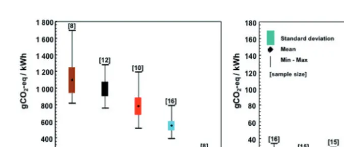
– nuclear is an almost CO2-free energy on the whole life-cycle, together with renew-ables [1,2], see fig. 1, hence global warming and related environmental concerns are substantially reduced;
– nuclear is a high-quality industry hence is usually used to improve and develop country’s economy, since the largest part of the investment is on the construction phase and not on the fuel cost as for the fossil fuels (likely to be covered with a C
Fig. 1. – Estimation of life-cycle CO2-equivalent emissions per electricity produced with different
fuels.
large disbursement outside the country), moreover that phase could be carried out with local industries for more than 50%.
The main interest in this source of energy is physically based on the so-called “mega factor”. When comparing the energy released by a chemical reaction, as in the com-bustion phase of a coal (C) atom or a methane (CH4) molecule, with a nuclear reaction on a nucleus of uranium (235U isotope) by a neutron (n), the amount of energy (Q, in ElectronVolt) differs from six orders of magnitude:
C + O2= CO2+Q(Q= 3.6 eV),
CH4+ 2O2= CO2+ 2H2O +Q(Q= 9.22 eV), 235U + n = F
1+ F2+νn +Q(Q= 211.5 MeV).
That means, on a larger scale, 5 grams of nuclear fuel (UO2) are energetically equivalent to 640 kg of wood, or 360 m3 of methane, or 400 kg of coal, or 350 kg of oil, moreover with no CO2 emissions.
Today, only a small amount of natural Uranium (which isotopic composition is: 234U, 0.006%;235U, 0.712%;238U, 99.282%)is exploited in the current, thermal nuclear reac-tors, since only the235U isotope undergoes fission with thermal neutrons. In the future, 70% of the natural content of this element could be used, by transmutation of the largest isotope (238U) into a fissile isotope with fast neutrons, in fast nuclear reactors.
The high energy density of this fuel reflects also in the land use and in the infrastruc-ture requirements of a power station.
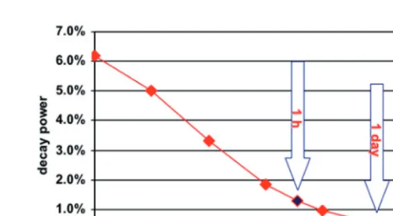
Fig. 2. – Nuclear decay power after shutdown.
While one single truck, loading the new fuel is required to annually operate a nuclear reactor, one oil tanker a week is needed for an oil-fired power station, or one trainload per day for the coal-fired power station, or the umbilical dependence from a pipeline for the gas-fired power station.
2. – Why a nuclear reactor is different from any other power plant
Together with the pros, come the cons.
Nuclear energy and nuclear reactors have unique, critical features that must be duly addressed, in order to exploit the above-mentioned positive characteristics while reducing the corresponding risks.
The main issues are on safety and nuclear waste, topics that are typical in any debate on nuclear. Those issues have their founding phenomenon in the fission event.
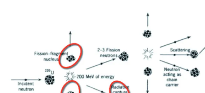
During that event, caused by a slow, thermal neutron interacting with a nucleus of 235U, more than 200 MeV of energy are released, the largest part as kinetic energy of
the couple of fission fragments that are generated. Those isotopes are rich in neutrons hence instable and decay to more energetically stable configurations by emitting energy, in radiation form. The fission fragments release that decay energy with delay after the fission event, with characteristics time ranging from seconds to years.
Fig. 3. – The nuclear fission chain reaction: energy released and nuclear waste generated.
A second unique feature is the possibility to increase the power of the nuclear reactor beyond the designed nominal power, behaviour impossible in the other power plants. The fission events and the neutron population are balanced during a normal, stable operation of the reactor: a constant production of neutrons generated by the previous fission events, generates in turn a constant and stable number of new fissions. A balanced chain reaction is reached when one neutron, among the 2 or 3 produced for each fission, is able to generate a further fission in the fuel. The remaining 1 or 2 neutrons are absorbed into the fuel, the structural materials of the reactor, the fluid acting as moderator and coolant, or leak from the reactor. If more than one neutron continues the fission process, the chain reaction could diverge, generating an exponential increase of the corresponding power. That means further safety systems are required for the nuclear reactor, able to stop the chain reaction as soon as the control is lost or whatsoever accident occurs. The shutdown control rods are neutron absorbers entering in operation in few seconds to stop the nuclear reaction.
A third unique feature, related to the nuclear waste issue, is related to the absorption of neutrons by the fuel, as mentioned before. The large amount of 238U present in the fuel, usually enriched only at 3–4% in the fissile isotope235U, leads to the transmutation of the heaviest Uranium isotope into further, heavier nuclides by neutron capture. Thus transuranic actinides like plutonium (Pu), americium (Am), curium (Cm) are created by sequential neutron absorption into the fuel. These actinides are rich in neutrons hence instable, radioactive alfa-emitters and several of them are long-lived (e.g., Pu half life is equal to 23 000 years).
A fourth feature is the possibility to trigger exothermic chemical reactions during severe accident scenarios, leading to hydrogen production. The cladding of the nuclear fuel is usually made of zirconium alloy, since that type of steel is a lower neutron ab-sorption material. But in case of severe accidents, typically with a loss of fuel cooling capabilities, if the cladding temperature rises beyond 1200 K the water steam reacts with the zirconium, which generates a fast oxidation that produces hydrogen, as occurred in Fukushima. The related safety systems to avoid such a scenario adopt hydrogen burners, catalytic recombiners or inertised containment buildings.
A fifth uniqueness of the nuclear reactors refers to economics. The production cost of electricity (¤/kWhe) is largely based (> 50%) on capital investment cost, i.e. the overnight cost of construction of the nuclear power plant plus the financial interests during the construction period, while the fuel costs are around 25%–30% and operation and maintenance costs the remaining part. Exactly the opposite than any other fossil fuelled power plant, where more than 70% of the cost of electricity production is the fuel cost. This cost structure implies that nuclear is competitive when fossil fuels cost is high and the cost of money is low.
3. – Basics of nuclear reactors
From a simplified, technical point of view, a nuclear reactor is a sort of nuclear boiler producing steam, which is sent to a turbine that moves a generator, hence producing electricity.
More than 80% of the nuclear power plants in operation nowadays belong to the pressurised water reactor (PWR) or to the boiling water reactor (BWR) type (see fig. 4). Both of them use water as moderator to slow down (thermalize) the neutrons to increase the fission probability of 235U, as well as fluid to cool the fuel. The main difference is that in PWRs the water is kept in liquid phase by high pressure (155 bar), to enhance the moderation feature, hence a secondary circuit is needed to produce the steam, while in BWR the steam is generated directly into the primary circuit and sent to the turbine.
The nuclear fuel is usually in the form of UO2 pellets, 8 mm diameter and 12 mm height, piled up into zircalloy cladding cylinders 3.5 m length. A square matrix 8×8 (BWR) or 17×17 (PWR) of those fuel rods forms one single fuel assembly. According to the size of the reactor, hundreds of fuel assemblies form the nuclear core, to be cooled by the water.
The shutdown control rods, the water cooling and the water injecting systems are the main safety systems connected to the primary and secondary circuits (only for PWRs) of the reactor.
Fig. 4. – Left: PWR type; right: BWR type.
then directed into a wet-well chamber by means of large piping that guide the steam into a suppression water pool, where it is condensed. Both the containments have to withstand also to external accidents, ranging from natural (tornadoes, floods, earthquakes) to man-made (airplane crash) events.
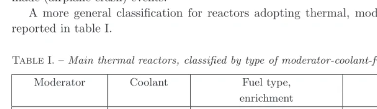
A more general classification for reactors adopting thermal, moderated neutrons is reported in table I.
TableI. –Main thermal reactors, classified by type of moderator-coolant-fuel.
Moderator Coolant Fuel type, Reactor type
enrichment
H2O H2O UO2,∼3% PWR, BWR
D2O D2O UO2, nat. CANDU
C H2O UO2, nat. RBMK
C CO2 U metallic, nat. MAGNOX
C CO2 UO2 or UC2, 1-2% up AGR
He to 93% HTGR
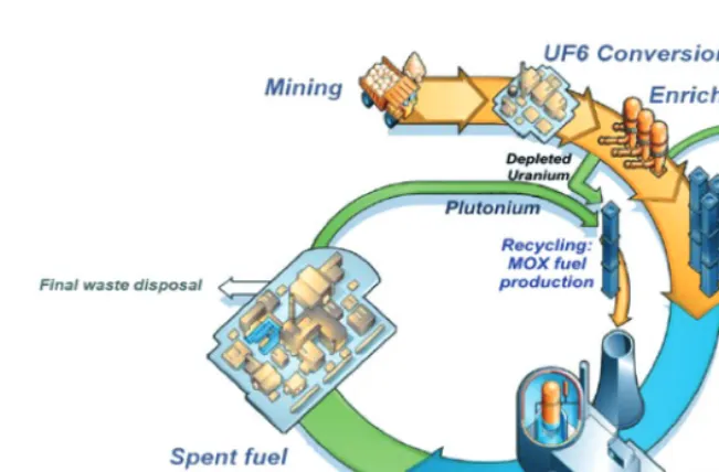
4. – Basics of nuclear fuel cycle
A long and complex journey is required to produce and manage the nuclear fuel (see fig. 5).
The ore of the natural uranium is mined with the same classical methods adopted in the mining industry, in open or underground mines, or is extracted by leaching.
The ore is then concentrated and purified, to eliminate all the rare earths and other chemical elements than UO2, that could represent a poison for the neutrons in the final nuclear fuel.
Fig. 5. – The main steps of the Nuclear Fuel Cycle.
i.e.increasing the235U content with respect to238U. The available enrichment processes are based on the gaseous diffusion across a porous membrane and on the ultracentrifuge technology. Both the processes exploit the different velocity or the different centrifugal force acting on the235UF6 molecules with respect to the238UF6ones. But the ultracen-trifugation method is more effective for the separation capacity (1 order of magnitude better than the gaseous diffusion) and for the energy consumption (50 times less than the electricity consumed by the gaseous diffusion).
Once enriched, the UF6must be re-converted into UO2 to create the fuel assemblies. The UO2powder is syntherised to form stable, ceramic pellets, which fill in the zircalloy fuel rods, than grouped in square matrix to create a fuel assembly.
The fresh fuel assemblies replace the spent fuel ones into the reactor, once the power plant is shutdown for refuelling and maintenance operations every 12–18 months.
The spent fuel contains mainly 238U (still > 95%), the fission fragments and the transuranic elements accumulated during the fuel burnup period, as well as some 235U the reactor was not able to burn. The transuranic elements include239Pu, a new fuel for the reactors but also a strategic element, used to produce the nuclear warheads.
Fig. 6. – Waste generation comparison: industrial and nuclear waste yearly produced in the European Union.
to efficiently reject the decay heat and to avoid any chemical or water attack in the millennia. The largest mass of the spent nuclear fuel is the depleted uranium 238U, stored in canisters on site.
A couple of options are envisaged as final solution for the high radioactive nuclear waste coming from the spent fuel: the final, geological repository and the waste burning. Nowadays some countries like Finland, Sweden and France are preparing the geological repository underground (around 500 m depth), in stable layers of rock or rock salt or clay, to place the whole spent fuel assemblies coming from the open cycle or the separated and concentrated nuclear waste coming from the closed cycle.
The alternative will be to transmute or “burn” the high radioactive and long-lived isotopes from the fission products and the transuranic elements into fast neutron reactors, usually liquid metal cooled. Some new generation reactors (or “Generation IV” reactors) are under development also for this purpose.
As a final annotation, the real burden given by the nuclear waste by comparison with the industrial waste annually produced should be considered. A self-explanatory picture is offered in fig. 6, referred to the EU production.
5. – Basics of nuclear safety
Since the beginning of the development of the nuclear energy, the nuclear safety is founded on the concept of “defence-in-depth”. A consecutive set of safety barriers, both of technological and operational type, is created around the source of the hazard,i.e.the nuclear fuel containing the highly radioactive isotopes.
The second barrier is represented by the fuel cladding, the third is the primary system boundary and the fourth is the containment building.
A further level of safety is offered by the set of safety systems connected to the primary, the secondary and the containment systems. Redundancy, separation and diversification are the key requirements, to reduce the risk of failure. Even if one single safety system is enough to cope with a specific accident, a multiplicity of two, three or even four is usually envisaged (redundancy). Moreover, different types of safety systems are adopted to obtain the same function (diversification).
The first safety system is the shutdown control rods system, to stop the reaction chain. A second is the decay heat removal system, to avoid fuel overheating. A third is the safety injection system, to keep the core cooled even in case of a break in the primary circuit, leading to a loss of coolant. A fourth is the containment spray system, to condensate the steam inside the pressure containment building. The same system is envisaged also inside the reactor pressure vessel for the BWRs.
The last operational barrier is represented by the emergency planning procedures, adopted to manage or evacuate the surroundings of the nuclear power plant in case all the previous safety barriers suffer some faults.
Both a deterministic and a probabilistic approach are followed in the design and the evaluation of the safety level of a nuclear reactor. The main goal is to minimise the risk of accident and to provide a suitable set of safety systems to cope with all the different and possible accident scenarios that may occur, in case of internal or external initiating events, natural or man-made.
But the real, estimated risk is usually different from the risk perception. So it is not surprising if the nuclear energy is perceived as less safe than the other energy sources or even other, daily-life human activities. Statistical data are anyway available in the literature, so a scientifically and technically based comparison can be performed. Again it would not be surprising, after that analysis, to see that to live around a nuclear power station is less risky than to be hit by lightning having a tour on the mountains, or to die at home due to a domestic accident or to die due to a collision while driving our own car.
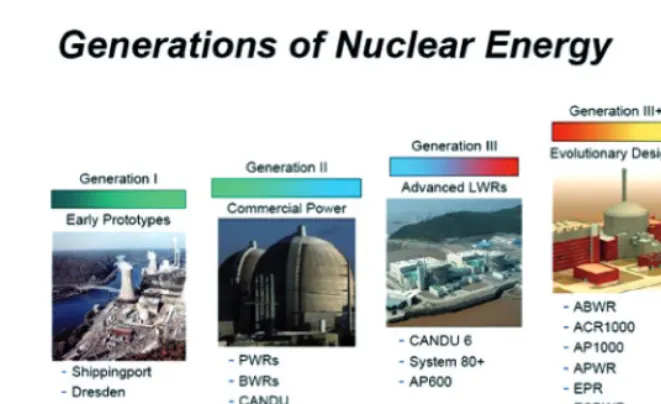
6. – Nuclear reactor generations
Several “generations” of nuclear reactors (see fig. 7) have been developed since the first demonstration of the possibility to ignite and control the fission nuclear chain reaction, by Enrico Fermi the 2nd of December 1942 under the Stadium of the University of Chicago. In the 50s and 60s, the first generation of nuclear reactors went into operation in the Western World as well as in Russia and in Japan: gas-graphite, PWRs and BWRs were the main technologies adopted, with sizes of the plant in the range of few dozens up to few hundreds of MWe.
Fig. 7. – Nuclear reactor generations: from the pioneering age to the next decades.
From the 90s up to the early period of the new millennium, another generation of nuclear reactors were developed, the so called Generation III or III+: almost in any country where the nuclear energy was well developed, advanced and innovative projects were launched.
The economy of scale was in some cases still the driver, but in other designs the system simplification including a size reduction was addressed. In all the new projects, higher safety level was the main goal, after the Three Mile Island and the Chernobyl events.
Two different safety strategies have been adopted: some designs implement a further enhancement of the “classic” active safety, with redundant and diversified systems rely-ing on energy sources (mainly electricity) external or internal to the site; other designs implement the “innovative” passive safety concept, where no or less need of electric-ity, mechanical components to be activated and human intervention are required, since the driving forces are usually based on “natural” physical principles, like the natural circulation of fluids at different temperatures hence densities.
Some examples of that different approach to reach a new, high level of safety are offered by the French EPR and the US-Japanese ABWR (see fig. 8), based on active systems, and by the US AP1000 and the US-Japanese ESBWR (see fig. 9), based on passive systems.
Fig. 8. – GenIII reactors based on Active Safety Systems. Left: EPR; right: ABWR.
enough to cope with the accident. Moreover, the containment system is a double con-crete building, the first conceived to address internal accidents and the related increase of pressure, the second to withstand external events including airplane crashes. Again, to minimise the unavailability of the safety systems even in case of external accidents, the four safety systems are distributed around the bunkered reactor containment. Also the four emergency diesel generators are placed in two bunkered buildings.
EPRs are now under construction in Finland, France and China.
The ABWR is an advanced boiling reactor, already built and in operation in Japan, large size (1350 MWe), with ten internal pumps placed at the bottom of the reactor pressure vessel, to avoid piping penetrations hence eliminating the risk of large primary piping breaks. It implements the better knowledge and active safety systems so far developed on BWRs.
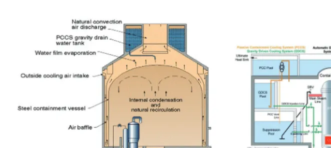
Based on the passive safety philosophy are the AP1000 and the ESBWR.
The first is a PWR, 1100 MWe size, with two instead of four primary loops and corresponding steam generators and active primary pumps, which adopts passive safety both for the primary and the containment systems. A large pool inside the containment is used as heat sink to reject the decay heat and as water supplier to inject coolant inside the reactor: both functions are performed in natural circulation hence without pumps and electricity. Moreover, also the containment building exploits external, natural circulation of air or evaporation of water for its cooling in case of accident, since it is made by steel instead of concrete. A second concrete external building protects the internal steel one from aircraft crash, tornadoes and similar events.
AP1000 reactors are under construction in US and China.
Fig. 9. – GenIII reactors based on Passive Safety Systems. Left: AP1000; right: ESBWR.
primary coolant flows in natural circulation, in normal operation. Several pools provide a large amount of water both for gravity injection into the core and for steam condensation hence heat rejection, in case of accident. Notwithstanding this fully natural behaviour, the reactor size is large: 1520 MWe.
Even severe accident scenarios are addressed in those designs. Some of them, like the EPR, apply the “ex-vessel” core retention strategy, with the melted corium assumed as released outside the primary reactor pressure vessel and then distributed in a suitable cavity under the reactor and there cooled. Other, like the AP1000, adopt the “in-vessel” core retention strategy, with the melted fuel collected at the bottom of the reactor pressure vessel and there cooled, both by the internal (water injection) and the external (cavity flooding) side.
In the path of development of nuclear reactor generations, the last, future step in the nuclear fission technology is the so-called Generation IV [3]. In 2000, ten Coun-tries launched an international committee of nuclear scientists and technical experts, to identify and select the nuclear technologies for the future, able to satisfy the main requirements of
– sustainability, with more effective nuclear fuel exploitation, less waste production and less long-time burden,
– economics,
– enhanced safety, with no need for emergency response,
– non-proliferation and physical protection.
Those types of reactor should be developed through an international cooperation and become available in the years 2030–2040. Mainly due to the challenging environments and operating conditions required, new materials and innovative solutions are needed. The Sodium-cooled and the Lead-cooled options seem the most promising in the expected time, given the experience gained in the past on those technologies.
The GenIV fast reactors are expected also to offer a ultimate contribution in solving the problem of the high level nuclear waste, since they could reduce the radiotoxicity of the transuranic elements and the long-lived fission products to acceptable levels in a reduced amount of time, from 100 000 to 300 years.
7. – A future after Fukushima?
Are all the new features and developments of nuclear reactors, described in the pre-vious sections, enough to ensure a future to the nuclear energy?
After Fukushima (see fig. 10), it seems hard to answer. But first of all, some items should be pointed out referring to the Japanese events. Some rough and brutal data may help: the earthquake and the resulting tsunami were cause of more than 14 000 deaths and 11 000 missing, hundreds of thousands evacuees, more than 100 000 buildings fully destroyed, 1 700 roads damaged, 50 bridges and one dam collapsed. The same brutal data referred only to the Fukushima-Daiichi nuclear power station, report 3 deaths due to non-radiation causes, 21 workers contaminated, almost all under the dose limits prescribed by the Japanese Safety Authority, 190 000 evacuees, soil and water contaminated and still under monitoring.
A recent preliminary report issued by the World Health Organisation on the health risk [4] assessment of the radiation doses released by the Fukushima reactors, concludes that a very small increase (4–7%) in the normal risk of generating leukaemia or a solid cancer in the whole lifetime could occur to the most affected populations (2 zones in the Fukushima Prefecture).
Moreover, the investigation committees that operated and operate in analysing the accident and the possible causes, at national as well as at international level, are
to re-evaluate the safety level of the current nuclear power plants. As a result, a large investment on safety upgrade is now foreseen for almost all the reactors.
The reaction of few countries, like Germany, Switzerland, Italy, has been the phase-out or the non-restart of the nuclear option, but in the largest part of the nuclear countries the result has been a delay or a confirmation of the activities in the nuclear sector. Several countries confirmed or launched the construction of new reactors (e.g. China, India, South Korea, United Arab Emirates, Finland, USA, Russia, UK, Slovakia).
It is very likely a future could exist for nuclear energy, even after Fukushima, but safety, in terms both of technology and organisation/regulation, will be and remain a hot topic to be duly addressed by the current as well as the future nuclear reactors. Together with nuclear waste and economics. They all will be key drivers for the new generation reactors: GenIII or GenIV nuclear power plants, or the so-called SMR-Small Modular Reactors, nowadays under development in several countries.
REFERENCES
[1] Weisser D., A guide to life-cycle greenhouse gas (GHG) emissions from electric supply
technologies, inEnergy, Vol.32(2007).
[2] Royal Society and Royal Academy of Engineering, Nuclear energy: the future climate (1999)
http://www.raeng.org.uk/news/publications/list/reports/nuclear energy.pdf
(accessed April 2013).
[3] GenIV International Forum,GIF R&D Outlook for Generation IV Nuclear Energy Systems (2009)
http://www.gen-4.org/PDFs/GIF RD Outlook for Generation IV Nuclear Energy Systems .pdf(accessed April 2013).
[4] World Health Organisation, Preliminary dose estimation from the nuclear accident after the 2011 Great East Japan Earthquake and Tsunami(2013)
http://www.who.int/ionizing radiation/pub meet/fukushima dose assessment/en/
(accessed April 2013).
Further reading
– UK Health and Safety Executive: www.hse.gov.uk/newreactors. – International Atomic Energy Agency: www.iaea.org.