TR-IMDEA-Networks-2014-3
Design and implementation of
and Android context-aware
application based on Floating
Content
Vittorio Cozzolino
Universit`
a degli studi di Napoli Federico II
Master Thesis
Design and implementation of and
Android context-aware application based
on Floating Content
Author:
VittorioCozzolino
Supervisor:
Dr. Simon PietroRomano
A thesis submitted in fulfilment of the requirements
for the degree of Master in Computer Science Engineering
in the
Research Group Name
Dipartimento di Informatica e Sistemistica
I, VittorioCozzolino, declare that this thesis titled, ’Design and implementation of and
Android context-aware application based on Floating Content’ and the work presented in it are my own. I confirm that:
This work was done wholly or mainly while in candidature for a computer science
engineer master degree at this University.
Where any part of this thesis has previously been submitted for a degree or any
other qualification at this University or any other institution, this has been clearly stated.
Where I have consulted the published work of others, this is always clearly
at-tributed.
Where I have quoted from the work of others, the source is always given. With
the exception of such quotations, this thesis is entirely my own work.
I have acknowledged all main sources of help.
Where the thesis is based on work done by myself jointly with others, I have made
clear exactly what was done by others and what I have contributed myself.
Signed:
Date:
”Computer science also differs from physics in that it is not actually a science. It does
not study natural objects. Neither is it, as you might think, mathematics; although it
does use mathematical reasoning pretty extensively. Rather, computer science is like
engineering; it is all about getting something to do something, rather than just dealing
with abstractions, as in the pre-Smith geology”
Abstract
Ingegneria Informatica
Dipartimento di Informatica e Sistemistica
Master in Computer Science Engineering
Design and implementation of and Android context-aware application based on Floating Content
Communication and information are two concepts that cannot be separated. Right now we are in the middle of the the Information Age (also known as the Computer Age, Dig-ital Age, or New Media Age), a period in human history characterized by the shift from traditional industry that the industrial revolution brought through industrialization, to an economy based on the information computerization [1].
During this Information Age, we saw how the way of exchanging information mutated and evolved towards more flexible, dynamic and infrastructure-less means with a tran-sition spanning from the advent of the personal computer in the late 1970s, to the Internet’s reaching a critical mass in the early 1990s, and finally to the smart-phones, with a widespread public application started late 2000s [1].
We started to feel the urge to be ”always connected” and so smart phones were born to fulfil our needs. They brought into the hands of every person the chance to access the Internet, share their experiences and feelings, upload photo and videos, playing online games and so on, whenever they had the chance to.
Content sharing via the Internet became a widespread means for people to foster their relationships irrespective of physical distance and smart phones supplied the perfect mean the exchange information in a mobile environment.
Right now, smarter mobile devices continue to dominate worldwide and Android is at the forefront. Total smart mobile device shipments worldwide grew by 37.4 percent annually during the first quarter to approximately 308.7 million units, according to the market insight firm. Overall, Android remains on top as 59.5 percent of all smart mobile devices shipped last quarter were running Google’s mobile operating system.
The growth of mobile computing, and the pervasiveness of smart user devices is pro-gressively driving applications towards context-awareness, i.e., towards applications and services that allow users to exploit ”any information that can be used to characterize the situation of an entity” [2]. But relying on infrastructure based networks for location-aware services may often not be desirable, while they are still essential to overcome distances and connect people around the world.
The net result is a best effort application for floating content in which: 1) information dissemination is geographically limited; 2) the lifetime and spreading of information depends on interested nodes being available; 3) traffic can only be created and caused locally; and 4) content can only be added, but not deleted [3].
This thesis is structured as follows:
• Chapter 1. Introduction on social media and content sharing.
• Chapter 2. Floating content networks, description and applications.
• Chapter 3. Bluetooth, characteristic and protocol overview.
• Chapter 4. Presenting ”Floaty”, an Android application for floating content net-works.
• Chapter 5. Performance evaluation and tests results.
Acknowledgements
The acknowledgements and the people to thank go here, don’t forget to include your project advisor. . .
Declaration of Authorship i
Abstract iii
Acknowledgements vi
List of Figures x
List of Tables xii
Abbreviations xiii
1 Content Sharing and Social Media 1
1.1 Introduction. . . 1
1.2 Classification of social media . . . 2
1.3 Mobile social media . . . 3
1.3.1 Mobile social media and business potential . . . 4
1.4 Ad-hoc Social Networking: Increasing Content Sharing Potential . . . 5
2 Floating Content Networks 7 2.1 Introduction. . . 7
2.2 Fundamental Properties . . . 8
2.2.1 System Basics. . . 9
2.2.2 System Operation . . . 10
2.3 Floating Content Theoretical Communication Protocol . . . 11
2.4 Protocol Limits and Challenges . . . 12
2.5 A Real Implementation . . . 14
3 Bluetooth 16 3.1 Introduction. . . 16
3.1.1 Bluetooth’s origins . . . 17
3.1.2 Bluetooth Stack Evolution. . . 17
3.2 Bluetooth’s protocol stack . . . 19
3.2.1 The OSI Reference Model . . . 21
Contents viii
3.3.1 Piconets and Scatternets. . . 23
3.3.2 Setting up Connections . . . 25
3.3.3 Discoverability and Connectability Modes . . . 27
3.4 Conclusions . . . 27
4 ”Floaty”: An Android Application for Content Sharing 28 4.1 Introduction. . . 28
4.2 Characteristics Overview. . . 28
4.3 Implementation Choices . . . 29
4.4 Application’s Structure . . . 31
4.4.1 Application’s Packages . . . 33
4.4.2 Application’s Class Diagram . . . 34
4.5 The Application Layer . . . 36
4.6 The Database Layer . . . 41
4.7 The Communication Layer. . . 43
4.8 Inter-node Communication . . . 43
4.8.1 Multiple Connections and the P2P Architecture . . . 45
4.9 Node-server Communication . . . 48
4.10 Support Functions . . . 48
4.11 Use Cases . . . 49
4.11.1 Scan Procedure . . . 49
4.11.2 Connection Procedure . . . 50
4.11.3 Exit Procedure and Data Upload . . . 50
4.12 Process Flowchart: Case One . . . 51
4.13 Process Flowchart: Case Two . . . 54
4.14 Process Flowchart: Case Three . . . 54
4.15 Conclusions . . . 58
5 Experimental Results and Performance Evaluation 59 5.1 Introduction. . . 59
5.2 Data Extraction and Parsing . . . 60
5.3 Tests Settings . . . 63
5.4 Tests Results . . . 65
5.5 Static Tests . . . 65
5.5.1 Test One . . . 65
5.5.2 Test Two . . . 69
5.5.3 Test Three . . . 72
5.6 Dynamic Tests . . . 75
5.6.1 Test One . . . 75
5.6.2 Test Two . . . 78
5.6.3 Test Three . . . 81
5.7 Efficiency Tests . . . 83
5.7.1 Battery Consumption Test . . . 84
5.7.2 CPU Utilization Test. . . 86
5.7.3 Memory Allocation Test . . . 88
6 Conclusions 92
List of Figures
1.1 Social Media Landscape . . . 3
1.2 Ad-hoc social . . . 6
2.1 Anchor Zone: Basic . . . 9
2.2 4-Phases Protocol. . . 12
3.1 Bluetooth Logo . . . 17
3.2 Bluetooth stack . . . 20
3.3 OSI and Bluetooth . . . 21
3.4 Piconets . . . 23
3.5 Scatternets . . . 24
3.6 Bluetooth Modes . . . 25
4.1 Smartphones’s Market Analysis . . . 31
4.2 Application’s structure . . . 32
4.3 Simple Activity Diagram. . . 34
4.4 UML Class Diagram . . . 35
4.5 Floaty’s Main Activity . . . 38
4.6 Floaty’s ”Logcat” Activity . . . 39
4.7 Floaty’s Network List Activity . . . 40
4.8 Local Database . . . 42
4.9 Flaoty P2P Architecture . . . 46
4.10 Simplified Data Upload Procedure . . . 48
4.11 Use Case Diagram . . . 50
4.12 Process Flowchart: Scan Procedure . . . 51
4.13 Process Flowchart: Connection Procedure . . . 52
4.14 Process Flowchart: Application Exit and Data Upload Procedure . . . 53
4.15 Process Flowchart: Use Case One . . . 55
4.16 Process Flowchart: Use Case Two . . . 56
4.17 Process Flowchart: Use Case Three. . . 57
5.1 Information Life Cycle . . . 59
5.2 Data Parsing Procedure . . . 61
5.3 Data Parsing Procedure : Efficiency . . . 62
5.4 IMDEA Building Planimetry . . . 64
5.5 Test One (Static): Total Contents Received . . . 66
5.6 Test One (Static): Single Content Evolution Graph . . . 67
5.7 Test One (Static): Histogram . . . 68
5.9 Test Two (Static): Total Contents Received . . . 69
5.10 Test Two (Static): Single Content Evolution Graph. . . 70
5.11 Test Two (Static): Histogram . . . 71
5.12 Test Two (Static): Availability . . . 71
5.13 Test Three (Static): Total Contents Received . . . 72
5.14 Test Three (Static): Single Content Evolution Graph . . . 73
5.15 Test Three (Static): Histogram . . . 74
5.16 Test Three (Static): Availability . . . 74
5.17 Test One (Dynamic): Total Contents Received . . . 76
5.18 Test One (Dinamic): Single Content Evolution Graph . . . 76
5.19 Test Three (Dynamic): Histogram . . . 77
5.20 Test Three (Dinamic): Availability . . . 78
5.21 Test Two (Dinamic): Total Contents Received . . . 79
5.22 Test Two (Dinamic): Single Content Evolution Graph . . . 79
5.23 Test Two (Dynamic): Histogram . . . 80
5.24 Test Two (Dinamic): Availability . . . 80
5.25 Test Three (Dinamic): Total Contents Received. . . 81
5.26 Test Three (Dinamic): Single Content Evolution Graph . . . 82
5.27 Test Three (Dynamic): Histogram . . . 82
5.28 Test Three (Dinamic): Availability . . . 83
5.29 Battery Consumption: Test One . . . 84
5.30 Battery Consumption: Test Two . . . 84
5.31 Battery Consumption: Test Three . . . 85
5.32 CPU Utilization: Test One . . . 86
5.33 CPU Utilization: Test Two . . . 87
5.34 CPU Utilization: Test Three . . . 87
5.35 Memory Allocation: Test One . . . 88
5.36 Memory Allocation: Test Two. . . 89
List of Tables
5.1 Test One (Static) . . . 65
5.2 Test Two (Static) . . . 69
5.3 Test Three (Static) . . . 72
5.4 Test One (Dynamic) . . . 75
5.5 Test Two (Dynamic) . . . 78
5.6 Test Three (Dynamic) . . . 81
FCN Floating Content Network
DTN Delay TolerantNetwork
BT BlueTooth
AZ AnchorZone
OSI OpenSystem Interconnect
API Application Programming Interface
P2P PeerTo Peer
GUI GraphicUser Interface
XML eXtensibleMarkup Language
MAC MediaAccessControl
CDF CumulativeDistributionFunction
For/Dedicated to/To my. . .
Content Sharing and Social
Media
This chapter shows what is a social media and why they are so important to share informations. Content sharing is theraison d’etre behind mobile networks and my work focuses on extending content sharing’s horizon to ad-hoc networks.
1.1
Introduction
Social media refers to the means of interactions among people in which they create, share, and exchange information and ideas in virtual communities and networks; it’s the conceptual starting point of content sharing.
Andreas Kaplan and Michael Haenlein define social media as ”a group of Internet-based applications that build on the ideological and technological foundations of Web 2.0, and that allow the creation and exchange of user-generated content.”
Furthermore, social media depends on mobile and web-based technologies to create highly interactive platforms through which individuals and communities share, co-create, discuss, and modify user-generated content. It introduces substantial and pervasive changes to communication between organizations, communities, and individuals. Social media differentiates from traditional/industrial media in many aspects such as quality, reach, frequency, usability, immediacy, and permanence.[5] There are many
Chapter 1. Content Sharing and Social Media 2
effects that stem from internet usage. According to Nielsen, internet users continue to spend more time with social media sites than any other type of site.
For content contributors, the benefits of participating in social media have gone beyond simply social sharing to building reputation and bringing in career opportunities and monetary income. [1]
1.2
Classification of social media
Social media technologies take on many different forms including magazines, Internet fo-rums, weblogs, social blogs, microblogging, wikis, social networks, podcasts, photographs or pictures, video, rating and social bookmarking. We can also see a differentiation based on the purpose and the target devices for each specific social ”portal”, as Figure 1.1
shows.
Technologies include: blogs, picture-sharing, vlogs, wall-postings, music-sharing, crowd-sourcing and voice over IP, to name a few. Many of these services can be integrated via social network aggregation platforms. By applying a set of theories in the field of media research (social presence, media richness) and social processes (self-presentation, self-disclosure) Kaplan and Haenlein created a classification scheme in their Business Horizons (2010) article, with six different types of social media:[1]
• Collaborative projects (for example, Wikipedia)
• Blogs and microblogs (for example, Twitter)
• Content communities (for example, YouTube and DailyMotion)
• Social networking sites (for example, Facebook)
• Virtual game worlds (e.g., World of Warcraft)
• Virtual social worlds (e.g. Second Life)
Figure 1.1: Social Media Landscape, 2012 [1]
1.3
Mobile social media
When social media is used in combination with mobile devices it is called mobile social media. This is a group of mobile marketing applications that allow the creation and exchange of user-generated content.
Due to the fact that mobile social media runs on mobile devices, it differentiates from traditional social media as it incorporates new factors such as the current location of the user(location-sensitivity)or the time delay between sending and receiving messages
Chapter 1. Content Sharing and Social Media 4
Mobile social media applications can be differentiated among four types:
1. Space-timers (location and time sensitive): Exchange of messages with relevance for one specific location at one specific point in time (e.g., Facebook Places; Foursquare)
2. Space-locators (only location sensitive): Exchange of messages, with relevance for one specific location, which are tagged to a certain place and read later by others (e.g., Yelp; Qype)
3. Quick-timers (only time sensitive): Transfer of traditional social media applica-tions to mobile devices to increase immediacy (e.g., posting Twitter messages or Facebook status updates)
4. Slow-timers (neither location, nor time sensitive): Transfer of traditional social media applications to mobile devices (e.g., watching a YouTube video or reading a Wikipedia entry)[1]
1.3.1 Mobile social media and business potential
While traditional social media offer a variety of opportunities for companies in a wide range of business sectors, mobile social media makes use of the location- and time-sensitivity aspects.
•Marketing research: Mobile social media applications offer data about off-line consumer movements at a level of detail heretofore limited to on-line companies. Any firm can now know the exact time at which a customer entered one of its outlets, as well as comments made during the visit.
• Communication: Mobile social media communication takes two forms, the first of which is company-to-consumer in which a company may establish a connection to a consumer based on its location and provide reviews about locations nearby. The second type of communication is user-generated content.
• Relationship development and loyalty programs: In order to increase long-term re-lationships with customers, companies are able to create loyalty programs that allow customers who check-in regularly at a location to earn discounts or perks.
• E-Commerce: Mobile social media applications such as Amazon.com and Pinterest are influencing an upward trend in the popularity and accessibility of e-commerce, or on-line purchases.
Business Marketing Analysts have stated that one of the key take away of the Nielsen Company’s ”State of the media: The social media report 2012”[6] is that more consumers are accessing social media content today via mobile platforms, especially apps.[1]
1.4
Ad-hoc Social Networking: Increasing Content
Shar-ing Potential
Both mobile industry and academia have been studying the potential of mobile phones to detect social proximity and to find effortless ways of communicating and sharing data with people nearby.
A new field of research using mobile devices as sensors for social interaction is being established around the topic of sensor-based mobile communication and ad-hoc net-working.
The next frontier for content sharing and social media is bringing it all into ad-hoc networks, where people can exchange contents to everyone in their proximity without any limitation as an Internet connection or an account connected to a social network. It can be considered the easiest and fastest way to share informations on the fly and probably it’s the best way to deal with geographically limited information that have no reason to be advertised on the Web (like a market broadcasting offers and discounts to users passing by).
Chapter 1. Content Sharing and Social Media 6
Figure 1.2
Floating Content Networks
In this chapter will be presented a particular type of DTN : Floating Content Net-works, on which my application is based and designed. The chapter will start with an introduction followed by an in deep analysis of all the characteristics of this kind of networks.
2.1
Introduction
Floating content concept is a specific example of networks with intermittent connec-tivity or so-called delay tolerant networks (DTN). DTN are an example of computer network architectures that seek to address the technical issues in heterogeneous net-works that may lack continuous network connectivity. Examples of such netnet-works are those operating in mobile or extreme terrestrial environments, or planned networks in space [1].
The floating content opportunistic communication paradigm perfectly suits the needs of context-aware applications, the benefit of opportunistic communications is that it nat-urally incorporates context as spatial proximity is closely associated with connectivity. Context awareness is a property of mobile devices that is defined complementary to location awareness. Whereas location may determine how certain processes in a device operate, context may be applied more flexibly with mobile users, especially with users of smart phones. Context awareness originated as a term from ubiquitous computing
Chapter 2. Floating Content Networks 8
or as so-called pervasive computing which sought to deal with linking changes in the environment with computer systems, which are otherwise static [1].
A simple example of context-aware application could be a shopping mall broadcasting information about the available discounts and offers of the day so that all the customers could receive directly on their devices the advertise without any effort, as soon as they get in range of the broadcaster. Another example could be a context-aware parking finding application. Information about a vacant parking spot may be of interest for a limited time(until the space is filled), and only to users who are in fairly close proximity.
2.2
Fundamental Properties
A FCN is assumed to consist of cluster of independent users, of which some of them moving according to a mobility pattern while some others could be stationary. Moreover, there is a specific region, the so-calledanchor zone, where users exchange the information item on condition that they are within each others transmission ranges.
Once a user exits the anchor zone, she can remove the local information that is considered obsolete outside the anchor zone. The transmission range is assumed to be the same for all users (in our case, it is enforced by the BT standard), and small relative to the dimensions of the anchor zone. No assumption is made regarding whether the number of nodes in the region is large enough to guarantee instantaneous connectivity; thus, user mobility is the key factor through which information is propagated [3].
2.2.1 System Basics
We assume that all users are mobile nodes and that there is no supporting infrastruc-ture for the system. The users are interested in information items “posted” by other users. We can consider that they use mobile phones or similar devices to communicate, equipped with enough memory to easily handle the amount of data exchanged during their permanence inside the network.
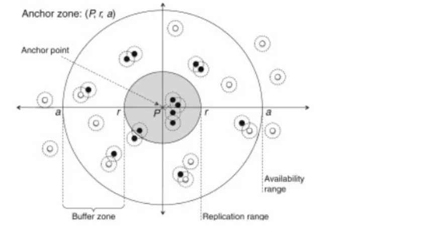
The devices have wireless interfaces (e.g., Bluetooth or WLAN) for ad-hoc communi-cation within a certain range, in our specific applicommuni-cation I decided, for reasons we will discuss in the later chapters, to use the BT interface. The nodes cooperate by replicating content among interested parties as we describe below. Each item has an anchor zone, which is a real world area in which the items should be made available. We assume cir-cular anchor zones defined by a center point and a radius. Figure 2.1shows an example of AZ.
Figure 2.1: An anchor zone of an item, mobile nodes and their communication ranges:
the content item gets replicated across and deleted from nodes as a function of. the distance from the anchor point. The probability of a node carrying an Item (black nodes) tends to I inside the anchor zone r and decreases until, after an availability
threshold a, no more copies are found.
Chapter 2. Floating Content Networks 10
Anchor zones require nodes to be able to estimate their position, e.g., by using GPS re-ceivers or triangulation-based methods using WLAN access points, cellular base stations, etc. Beeing a probabilistic system, there are no strict requirements on the accuracy of positioning techniques; nodes are only required to agree on measurement parameters and the overall operation to determine the extent of anchor zones. [3]
2.2.2 System Operation
A node generates an information itemX of sizes(X)and assigns an anchor zone (defined by its center and its radius) as well as a time to live T(x) for this item. As shown in Figure 2.1, r defines the replication range within which nodes always replicate the information to other nodes they meet, a defines theavailability range within which the content item is still kept around with limited probability, while outside a no copies are to be found. [5]
We require that the generating node be within the anchor zone at the moment of item creation. If two nodes A and B meet in the anchor zone of an itemX, and A hasX and B does not have it, then A replicates item X to B. [4]
Every node in the anchor zone should have a copy of the item, since replication is based purely on the location of nodes, in a simple scenario. Nodes leaving the anchor zone are free to delete their own copy of the item. In practice, replication and deletion works as follows.
Consider a node A having an item X, with an anchor zone defined by center point c
and radius r. Let d denote the distance of node A from point c. When node A meets another node B, A will replicate item X to B with probabilityp, wherep is given by:
p=
1 ifd≤r
R(d) otherwise
where R(d) [0,1] is some (decreasing) function that gives the probability of replication outside the anchor zone.
of nodes moving outside the anchor zone for a brief moment and then returning. We define an availability rangea (see Figure 2.1) beyond which copies are deleted.
Any user generating a content can define the extent of his own anchor zone. The anchor zone is characterized by its center and radius and it is sufficient for the user to be in the anchor zone at the time of creation. There are no limit on how the user can define the anchor zone.
2.3
Floating Content Theoretical Communication
Proto-col
Now we will show which are the standard operations that nodes inside a FCN normally execute, following a 4-phase protocol defined in [5] to exchange messages. A content message m is identified by a unique message id Idm and can be slitted in two parts:
header and payload. Header contains all the information about the generating AZ, the payload the real message to exchange.
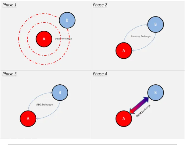
Let’s see the 4-phase protocol in action :
1. Nodes continuously send neighbour discovery beacons to discover peers.
2. After discovering a peer, i.e. receiving a beacon, a node sends a summary message that includes a vector of the content items available for replication, i.e., all items for which p >0 at the node’s present location. The summary may be limited to what fits into one MTU size packet (or otherwise to a message sufficiently small to be exchanged efficiently so that most of the per-contact communication capacity is left to exchange content).
3. As soon as a device is aware of what a neighbour has to offer, it requests a subset of the content items: the receiver requests all those items for which evaluating p
so suggests.
Chapter 2. Floating Content Networks 12
Figure 2.2: Nodes A discovers B during Phase 1 and then follows protocol phases
described above
All phases are fully bidirectional so that message exchanges take place in both ways simultaneously. The protocol does not restrict message exchange to two nodes at a time, even though some link layer technologies may (in our implementation we faced this problem, but we will discuss this in the next chapter). Beaconing is continued throughout the message exchange process so that new nodes may be discovered while a node is already exchanging messages with another.
2.4
Protocol Limits and Challenges
The characteristics of floating content described above show interesting opportunities but also exhibit notable challenges.
some degree of privacy: users have to be present to see something, a concept intuitively familiar from daily life.
The major challenge is the best-effort operation: users cannot be guaranteed that in-formation will stay around until its intended lifetime expires. Especially, content is expected to ”sink” from public places over night. Again, however, users can make intu-itive judgements: if a user is on a crowded market square, a busy street, or in a lively bar, chances are that content will float for a while, even if not all other people have floating content-enabled mobile devices.[5]
Given density fluctuations over the day due to people’s activities, we would expect floating content to remain likely available for no more than a few hours (just one hour would be sufficient for various applications).
There are different kind of applications that we can take into account and make full advantage of the floating content paradigm. One class of applications for infrastructure-less best-effort local data availability in the order of one to a few hours is advertising and brokering for goods. While this also includes products and services in the legally gray area, announcing goods available on flea markets or bazaars is one example. We could have shops broadcasting a catalogue with their products at fixed time rate, that gets updated on the fly.
Another class includes localized infrastructure-less content sharing among users, like bypassing censorship when spreading news (and keeping information localized and time-bounded as a protection against prosecution).
We also expect floating content to be useful for leaving notes to people when moving from one place to the next, e.g., to inform latecomers of the next meeting point. Note that a special case of this is instant content sharing in a co-located group (photos, music, videos); here, no best-effort issue arises as the content origins stay around.[5]
Of course, like almost all communication protocol, floating content is affected by some security flaws, due to its distributed nature. We can find the following issues :
Chapter 2. Floating Content Networks 14
2. It is possible for a spammer to move and create items with small anchor zones everywhere. There is no mechanisms to guard against this. Instead, we consider the effort of having to move around to be a sufficient deterrent to most spammers. But still the problems is there.[5]
3. Basically, floating content approach does not require any security infrastructure or any degree of mutual trust. This could lead to nodes that spam their immediate neighbour or perform DoS attacks, but they could achieve the latter by using the physical layer interference anyway.
The floating content concept is inherently best effort; in contrast to this notion in the Internet, where close-to-instant repair mechanisms can recover lost packets, data that sunk is irrecoverable in an area (unless the originator returns). This shows clearly how much this communication paradigm is based onopportunistic exchanges.
2.5
A Real Implementation
Several studies has been made on FCNs, all of them with different purposes and focus. Results are extremely interesting and spans over a wide array of arguments :
• In [5], the fundamental objective of the work was deriving the so-calledcriticality condition guaranteeing the availability of the information within the anchor zone with a high probability. This depends on the mobility patterns of the users and on their density.
• [3] studied the floating content concept and, in particular, the expected lifetime
of the information in such systems. They developed a theoretical framework to analyse the floating content concept at regime.
• [4] focused on evaluating the general feasibility of floating content system by cover-ing a wide array of parameters like number of nodes, communication range, anchor zone radius and node mobility patterns.
Chapter 3
Bluetooth
One important step before presenting the application is giving a brief overview of the technology used to support the communication protocol used in my application: Blue-tooth. The chapter will start with a small introduction about the history and evolution of Bluetooth, followed by more technical aspects.
3.1
Introduction
Bluetooth is a wireless technology standard for exchanging data over short distances (using short-wavelength radio transmissions in the ISM band from 2400–2480 MHz) from fixed and mobile devices, creating personal area networks (PANs) with high levels of security.[1]
Created by telecom vendor Ericsson in 1994, it was originally conceived as a low cost, low power short-range radio technology developed as a cable replacement to connect devices such as mobile phone handsets, headsets, and portable computers.
Bluetooth specification is an open and global specification defining the complete sys-tem from the radio right up to the application level. The protocol stack is usually implemented partly in hardware and partly as software running on a microprocessor.
Figure 3.1: Bluetooth Logo [1]
3.1.1 Bluetooth’s origins
Version 1.0 of the Bluetooth specification came out in 1999, but Ericsson Mobile Com-munications began a study to examine alternatives to the cables that linked their mobile phones with accessories five years earlier.
The study looked at using radio links and allowing connections that could handle both speech and data. Radio isn’t directional, and it doesn’t need line of sight, so it has ob-vious advantages over the infra-red links preob-viously used between handsets and devices. Out of this study was born the specification for Bluetooth wireless technology.
The specification is named after Harald Blatand, a tenth century Danish Viking king who united and controlled Denmark and Norway. The name was adopted as Bluetooth wireless technology is expected to unify the telecommunications and computing indus-tries.
3.1.2 Bluetooth Stack Evolution
Chapter 3. Bluetooth 18
standards are designed for downward compatibility. That lets the latest standard cover all older versions.
The following list reports only the most important BT versions, skipping the ones that brought minor fixes and changes.
• Bluetooth v1.0 and v1.0B. Versions 1.0 and 1.0B had many problems, and man-ufacturers had difficulty making their products interoperable. Versions 1.0 and 1.0B also included mandatory Bluetooth hardware device address (BDADDR) transmission in the Connecting process (rendering anonymity impossible at the protocol level), which was a major setback for certain services planned for use in Bluetooth environments.[1]
• Bluetooth v1.2. This version include the following major enhancements: Faster Connection and Discovery, Adaptive frequency-hopping spread spectrum (AFH), which improves resistance to radio frequency interference by avoiding the use of crowded frequencies in the hopping sequence. Extended Synchronous Connections (eSCO), which improve voice quality of audio links by allowing retransmissions of corrupted packets, and may optionally increase audio latency to provide better concurrent data transfer. Host Controller Interface (HCI) operation with three-wire UART. Introduced Flow Control and Retransmission Modes for L2CAP.[1]
• Bluetooth v2.0. This version of the Bluetooth Core Specification was released in 2004 and is backward compatible with the previous version 1.2. The main difference is the introduction of an Enhanced Data Rate (EDR) for faster data transfer. The nominal rate of EDR is about 3 Mbit/s, although the practical data transfer rate is 2.1 Mbit/s. EDR uses a combination of GFSK and Phase Shift Keying modulation (PSK) with two variants,π/4-DQPSK and 8DPSK. EDR can provide a lower power consumption through a reduced duty cycle.
introduced other major changes : L2CAP Enhanced modes, Alternate MAC/PHY, Unicast Connectionless Data, Enhanced Power Control.
• Bluetooth v4.0. The Bluetooth SIG completed the Bluetooth Core Specification version 4.0 and has been adopted as of 30 June 2010. It includes Classic Bluetooth, Bluetooth high speed and Bluetooth low energy protocols. Bluetooth high speed is based on Wi-Fi, and Classic Bluetooth consists of legacy Bluetooth protocols. Bluetooth low energy (BLE) is a subset of Bluetooth v4.0 with an entirely new protocol stack for rapid build-up of simple links. As an alternative to the Bluetooth standard protocols that were introduced in Bluetooth v1.0 to v3.0, it is aimed at very low power applications running off a coin cell. Chip designs allow for two types of implementation, dual-mode, single-mode and enhanced past versions. General improvements in version 4.0 include the changes necessary to facilitate BLE modes, as well the Generic Attribute Profile (GATT) and Security Manager (SM) services with AES Encryption.[1]
3.2
Bluetooth’s protocol stack
A key feature of the Bluetooth specification is that it aims to allow devices from lots of different manufacturers to work with one another. To this end, Bluetooth does not just define a radio system, it also defines a software stack to enable applications to find other Bluetooth devices in the area, discover what services they can offer, and use those services. [6]
The Bluetooth stack is defined as a series of layers, though there are some features which span across several layers. Every block in Figure corresponds to a chapter in the core Bluetooth specification.
Chapter 3. Bluetooth 20
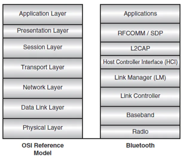
3.2.1 The OSI Reference Model
For the sake of completeness, it is useful to understand the structure of the Bluetooth stack compared to the well known Open Systems Interconnect (OSI) model, the standard reference model for communication protocol stacks. It is a useful exercise to relate the different parts of the Bluetooth stack to the various parts of the model.
Figure 3.3: Bluetooth stack compared to OSI
Since the reference model is an ideal, well-partitioned stack, the comparison serves to highlight the division of responsibility in the Bluetooth stack. In the following list are listed the different layers and their responsibilities:
Chapter 3. Bluetooth 22
• The Data Link Layer is responsible for transmission, framing, and error control over a particular link, and as such, overlaps the link controller task and the control end of the baseband, including error checking and correction [6].
• The Network Layer is responsible for data transfer across the network, independent of the media and specific topology of the network. This encompasses the higher end of the link controller, setting up and maintaining multiple links, and also covers most of the Link Manager (LM) task.
• The Transport Layer is responsible for the reliability and multiplexing of data transfer across the network to the level provided by the application, and thus overlaps at the high end of the Link Manager and covers the Host Controller Interface (HCI), which provides the actual data transport mechanisms [6].
• The Session Layer provides the management and data flow control services, which are covered by L2CAP and the lower ends of RFCOMM/SDP.
• The Presentation Layer provides a common representation for Application Layer data by adding service structure to the units of data, which is the main task of RFCOMM / SDP.
• The Application Layer is responsible for managing communications between host applications.
3.3
Communication Paradigm
When slaves connect to a master, they are told the Bluetooth device address and clock of the master. They then use this to calculate the frequency hop sequence. Because all slaves use the master’s clock and address, all are synchronised to the master’s frequency hop sequence.
In addition to controlling the frequency hop sequence, the master controls when devices are allowed to transmit. The master allows slaves to transmit by allocating slots for voice traffic or data traffic. The Master controls how the total available bandwidth is divided among the Slaves by deciding when and how often to communicate with each Slave. The number of time slots each device gets depends on its data transfer requirements. The system of dividing time slots among multiple devices is called Time Division Multiplexing (TDM). [6]
3.3.1 Piconets and Scatternets
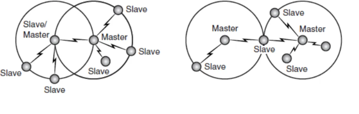
Bluetooth devices normally organize themselves in ”piconets” (or ”scatternets”, when there are multiple overlapping piconet). A collection of slave devices operating together with one common master is referred to as a piconet (see Figure ). All devices on a piconet follow the frequency hopping sequence and timing of the master.
Figure 3.4: Point to point and point to multipoint piconets
In Figure
Chapter 3. Bluetooth 24
The specification limits the number of slaves in a piconet to seven, with each slave only communicating with the shared master. However, a larger coverage area or a greater number of network members may be realized by linking piconets into a scatternet, where some devices are members of more than one piconet. [6]
When a device is present in more than one piconet, it must time-share, spending a few slots on one piconet and a few slots on the other.In Figure we can see that on the left is a scatternet where one device is a slave in one piconet and a master in another, while on the right is a scatternet where one device is a slave in two piconets.
Figure 3.5: Example of scatternets
A device is not allowed to be the master (all slaves in a piconet are synchronised to the master’s hop sequence) of two different piconets and all devices with the same master must be on the same piconet.
3.3.2 Setting up Connections
The process of establishing a connection via BT is rather complex and requires several steps. In this chapter I will present only a brief overview of the bonding process that runs between two devices.
By looking at Figure 3.6, it is possible to see the different states in which a BT device can be.
Figure 3.6: Flux diagram of Bluetooth’s states.
Establishing a connection between two Bluetooth devices follows a relatively complicated procedure meant to ensure a certain amount of security, as follows:
• During normal use, a device operates in”Standby”, meaning that it is listening to the network.
Chapter 3. Bluetooth 26
• The master device chooses an address and synchronizes with the slave using a technique called paging, which primarily involves synchronizing its clock and fre-quency with the access point. A link with the slave is then established, allowing the master device to enter a slave service discovery phase, using a protocol called
SDP (Service Discovery Protocol). The SDP protocol allows the master to to find out whether a device supports a particular service.
• At the end of this service discovery phase, the master device is ready to created a communication channel with the slave, using the protocol L2CAP. Depending on the service’s needs, an additional channel, called RFCOMM and operating over the L2CAP channel, may be established in order to provide a virtual serial port. Indeed, some applications have been designed to connect to a standard port, independent of the hardware used. [6]
It is worth to remember that the slave may include a security mechanism called
pairing, which restricts access to authorized users only, in order to give the piconet a certain measure of protection. Pairing is done in several ways that can be distin-guished between pre Bluetooth v2.0 (namely Legacy Pairing) and post Bluetooth v2.0 (namelySecure Simple Pairing, SSP).
– Legacy Pairing. This is the only method available in Bluetooth v2.0 and before. Each device must enter a PIN code; pairing is only successful if both devices enter the same PIN code. Any 16-byte UTF-8 string may be used as a PIN code; however, not all devices may be capable of entering all possible PIN codes (like Bluetooth Hands-free headsets, that use a fixed value PIN code) [1].
– Secure Simple Pairing. This is required by Bluetooth v2.1, although a Blue-tooth v2.1 device may only use legacy pairing to interoperate with a v2.0 or earlier device. It uses a form of public key cryptography, and some types can help protect against man in the middle, or MITM attacks. SSP has the following characteristics [1]:
∗ Numeric comparison: If both devices have a display and at least one can accept a binary Yes/No user input, they may use Numeric Comparison. This method displays a 6-digit numeric code on each device.
∗ Passkey Entry: This method is rather similar to the previous one except that the password can be made also of alphanumeric characters.
∗ Out of band (OOB): This method uses an external means of commu-nication, such as Near Field Communication (NFC) to exchange some information used in the pairing process.
• After the pairing process, the two devices are free to use the communication chan-nel thereby established.
3.3.3 Discoverability and Connectability Modes
It is important to realise that for a connection to be established using Bluetooth wireless technology, both ends of the link have to be willing to connect.
Some devices may be set so that they will not scan for inquiries; in this case, other devices cannot discover them, and they will effectively be invisible. Similarly, some devices may be set so that they do not perform page scans. In these cases, they can still initiate connections, but they will not hear other devices trying to connect to them. Applications can choose whether to make devices connect-able or discoverable. A con-nection cannot be forced on a device which is not in the correct mode to accept it [6].
3.4
Conclusions
Chapter 4
”Floaty”: An Android
Application for Content Sharing
In the previous chapters I proposed a background to my application by explaining the reasons and technologies behind it. In this chapter I will present in details the structure, functionality and characteristics of my application and how I made the best of Android API.
4.1
Introduction
Floaty is an Android P2P application based on content sharing in floating content net-works. It is based on Android native API and uses Bluetooth to allow several terminals to communicate and exchange informations in a totally distributed environment. Floaty is compatible with all Android terminals with API version 10+.
4.2
Characteristics Overview
Before delving further into the application structure, it is worth giving a brief overview of the functionality offered by Floaty.
Floaty’s main purpose is to create a peer-to-peer mesh network by interconnecting all terminals in proximity. This means that terminals have the opportunity to drop-in/
drop-out from the network in a seamless way. The application is designed so that as soon as a terminal joins the network it receives informations about all the other terminals and can exchange its informations as well to everyone it meets.
Terminals are smart-phones, this means that, for example, a node running Floaty and passing by a network of nodes interconnected and running the application, would be able to exchange with them informations. The exchanged information has geographical validity, as we discussed in 2, terminals will replicate and store a message only if they are inside the AZ, otherwise they will just delete it. To simplify the concept of AZ, in my application I decide to use WiFi AP as AZ.
This approach reflects FCNs communication paradigm, as we saw in Chapter2; terminals exchange contents in a viral way, allowing all the network to receive the information and store/ forward it, increasing the chances to reach ”convergence” (a point where the whole network possess a particular information).
To simulate this exchange of informations, the application is shipped with simple chat functionalities, so that, the end user, via a GUI, is able to interact with it (actually, the application is designed to work also without human interaction, for the sake of testing). All the communications between terminals are handled by the Bluetooth interface and there is no need for any human interaction for the terminal’s authentication (everything is done under the table by the application).
Thou Android’s API offers a limited array of functionalities to interact with the BT adapter and it is affected by a lot of design limitations, I managed to adapt it at best to support all the functionalities for my application to run. This particular matter will be discussed in details later in this chapter.
4.3
Implementation Choices
Before exploring in details the application, it is worth to explain to the reader why I made some specific and critical implementation choices.
Chapter 4. ”Floaty”: An Android Application for Content Sharing 30
the major number of possible devices; right now, WiFi Direct is available only for the most recent smart-phones, and thus would drastically reduce the number of target devices for my application. Said this, I’m not excluding the possibility, in the near future, to introduce into my application a module based on WiFi Direct (considering its great potentials, like increased TX range and greater protocol flexibility, reliability and functionalities), but for now I believe that it’s better to stick to the BT technology.
Another critical reason lays into the limitations that the actual WiFi Direct stan-dard has. Before dropping the option to use WiFi direct, I run some simple tests and I noticed that, unfortunately, current Android API do not allow an authenti-cation paradigm, between network nodes, without human interaction: WiFi direct requires always the user to accept an incoming connection.
• Android instead of Apple iOS. I decided to develop my application for Android OS instead of Apple iOS mostly because the number of devices running Android is greater than the ones running iOS. Based on latest IDC estimates, Android has expanded its reach around the world with a remarkable 73% growth in shipments year-over-year giving it a commanding 79% of the market. Apple’s iOS growth continues (albeit 20%), but at the expense of market share, down from 16.6% to 13.2%, no doubt being eaten away by its rival.
Actually it is possible to port applications from Android to iOS and vice-versa, so it the near future I do not exclude the possibility to port also my application to Apple operative system.
Figure 4.1
4.4
Application’s Structure
The following Figure shows the application’s main structure, divided into three main blocks, enveloped by the Android OS:
Chapter 4. ”Floaty”: An Android Application for Content Sharing 32
Figure 4.2: Simplified block schema of the application.
• Database Layer. This layer takes care of storing all the information gathered during the application execution, so that they can be shown to the user and communicated to other devices, eventually. It also stores informations about the topology of the network, the nodes that we met and what they sent to us.
• Communication Layer. This layer is the application’s core. Inside this layer it’s possible to find all the functionalities that allow our terminals to communicate, according to the floating content paradigm, and exchange data. This layer required a lot of work a fine-tuning to reach it final state, it has been reworked a lot of times to adapt to Android’s Bluetooth API limitations.
4.4.1 Application’s Packages
The application itself is composed of five packages (each package contains at least an activity) as shown in Figure 4.3:
• com.vittorio.Splashscreen. This is the package for the application’s splash screen.
• com.vittorio.TabContainer. This packages handles the multi-tabbed application structure; it’s the ”host” for the other tabs, it defines the layout where the actual tabs will find place.
• com.vittorio.Floaty. This is the main package and the first tab of the application (the ones that the user sees after the splash screen).
• com.vittorio.SecondTab. This package contains the application’s second tab.
Chapter 4. ”Floaty”: An Android Application for Content Sharing 34
Figure 4.3: This picture it’s a simplified view of the application. It shows in which
order the activities are called and started after the user starts the application. It is worth to notice that the ”Tab Container Activity” only starts the activity contained in the first tab, the others are really instantiated the moment we switch from the first
tab to another one (in the figure I made a small abuse of notation).
4.4.2 Application’s Class Diagram
At the beginning of this chapter, I roughly exposed the application’s structure by divid-ing it in three main layers. Now I will correlate each class of the class diagram to one of the three layers depicted before (some classes may belong to more than one block). In Figure 4.4only the main package class diagram is shown, the others are not included because they just contain one class each.
Figure
4.4:
Application
class
Chapter 4. ”Floaty”: An Android Application for Content Sharing 36
4.5
The Application Layer
The application layer contains all the classes that play a fundamental role in the creation of the application’s GUI. Figure shows the three tabs one next to the other, the first the the user sees is the first on the left. The splash-screen is not included on purpose, it is not relevant for the purpose of this discussion.
The classes involved into the creation of the GUI are :
• Splash.java. This activity’s only purpose is to present to the user a temporary splash screen and starting the tab container activity after a little delay. This delay proved itself to be useful by giving the system a small time frame in which it can start the Bluetooth adapter and the WiFi interface; from the user perspective it’s like a boot-up phase.
• Floaty.java. Activity to handle the creation of the first and main application tab. This tab is designed to track the nodes that are around the user and the informations received by them.
• FloatyLog.java. Activity to handle the creation of the second tab. It has been implemented solely for testing purposes and it allows the user to see a filtered version of theLogcat (this functionality works only on rooted devices).
• FloatyNetworkList.java. Activity to handle the creation of the third tab. In this tab the user can find information about both WiFi AP and BT devices in range.
It is worth to spend some lines to explain how the user can interact with the application, it will be useful to later understand better the use cases presented later in this chapter. Figure 4.5shows the first tab activity that the user sees after the splash-screen and can access by clicking on the paper plane icon. It is composed by the following elements:
• An EditText field (identified by letter ”A”), where the user can write a custom message to send to all nodes in proximity.
”C”). I will discuss further about what data are actually exchanged in the next section.
• The ”Send” button, used to broadcast the message that the user wrote.
• The ”Generate Content” button, used to start an automated process of content generation at a fixed rate, to be broadcasted to all the nodes in proximity. It’s a functionality mainly used to run tests and experiments to simulate an user gener-ating new contents each now and then.
• The”New Scan” button, used to scan for new devices in proximity and to refresh the terminal ”location” by scanning for WiFi AP.
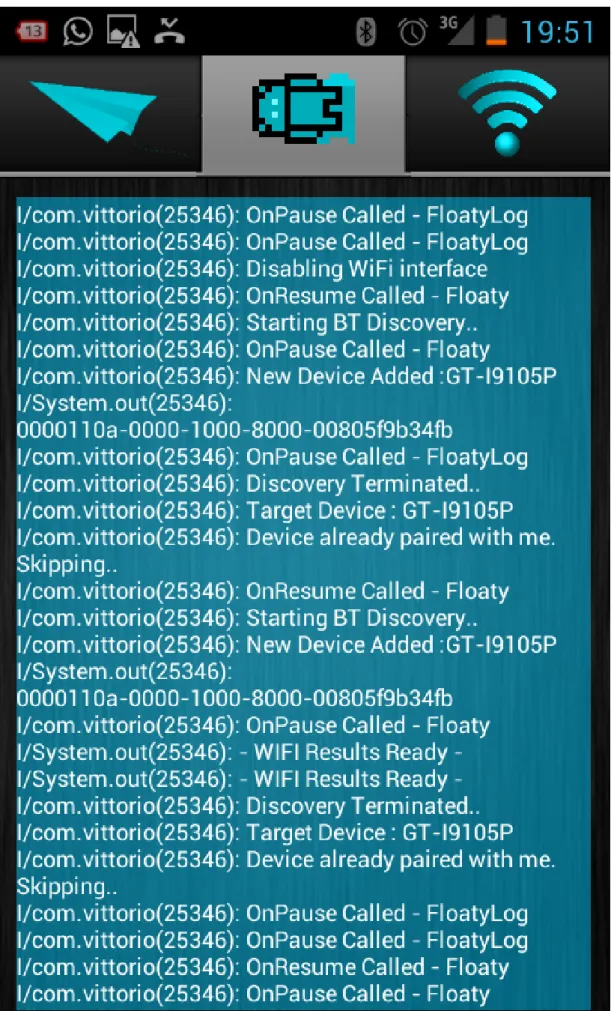
Figure 4.6 shows the second tab activity that the user sees by pressing on the Logcat icon. It is composed by the following components:
• A single TextView that spans allover the screen, it contains the filtered Logcat produced by the application. The user cannot interact with it, it’s used for testing purposes, for example to understand what kind of problem is afflicting a particular node without the need to plug it to a computer.
Figure 4.7 shows the third and last tab activity that the user sees by pressing on the WiFi icon. It is composed by the following components:
• Two ListView containing all the Wifi AP and BT devices in range (respectively identified, letter ”A” and ”B”). By long pressing on one of the entries inside the BT devices’s lists, a drop-down menu will appear granting the user two options : send the latest generated content to the target device or force the application to connect to it.
Chapter 4. ”Floaty”: An Android Application for Content Sharing 38
Chapter 4. ”Floaty”: An Android Application for Content Sharing 40
Figure 4.7: Application’s third activity used to list all WiFi AP and BT devices in
4.6
The Database Layer
The Database Layer main purpose is to store relevant data received from the nodes and informations about the network structure. Two classes can be associated with this layer:
• DeviceDB.java. This class stores informations about everything related to the network ”status”:
– A list containing all the nodes that I see in the network, based on the scanning procedure.
– A list containing the nodes that I’m connected to.
– A list containing the nodes that are connected to me.
– A list containing the nodes that I was not able to contact in the last connection round.
– A list containing all the WiFi AP the application found in proximity.
Those informations are extremely useful for the communication layer, but I will discuss further about it in the next subsection.
• DataTable.java. This class stores informations related to the data received and sent by/ to the nodes in the network. Each node sends to the ones it connects to a list of informations, each entry inside the list is in the shape of a DataSet, an object defined by the hidden class DataSet.java; each DataSet is associated with a unique device and contains the following informations:
– Name. It’s the name of the device (more precisely, it’s the BT adapter name).
– MAC Address. It’s the BT interface MAC address. While the ”Name” field may not be unique, the MAC address id be definition unique and it’s used to associate a DataSet unequivocally to a specific node.
Chapter 4. ”Floaty”: An Android Application for Content Sharing 42
– Data. The actual information that the node is exchanging, in my application it’s a String but it can be anything.
– Time. It can be seen as another time-stamp expressed with a conventional time format (”HH:mm:ss”).
– Content Counter. It’s a counter that counts the amount of contents generated by a node.
– Range detector. It’s a boolean flag used to detect if the node that sent me the information is in my WiFi zone or not (in my case every WiFi AP is considered and Anchor Zone).
– WiFi Zone. The name of the closest WiFi AP the nodes is near to.
All this informations are extremely useful to measure and analyse the network behaviour. Each node saves a snapshot of the network ,based on the informations present inside the DataTable class, on a file saved on the internal phone memory.
Figure 4.8: In the above figure we can see a small full mesh network with three nodes.
Those snapshots are taken whenever something changes inside the network topology, a new information is received by another node or the node itself generate a new infor-mation. This event-based procedure allows my application to keep track of everything happens inside the network.
Figure 4.8shows a simplified view of each node local database.
All the snapshots gathered over time represent the network evolution across the ap-plication execution and can be translated into valuable graphs and statistics. Those informations need to be post-processed and filtered, but I will talk about this step in the next section.
4.7
The Communication Layer
The communication layer it’s the pillar that sustains the whole application. The ap-plication and database layer exists solely to support to the communication layer with, respectively, a graphical interface and a storage; without this layer the other two would have no mean to exist.
Inside the communication layer it’s possible to find a lot of classes with different roles and I will present each of them thoroughly. I will divide further those classes in three figurative groups:
• Inter-node communication. This group contains all the classes that allow the nodes to exchange data.
• Node-server communication. This group contains all the classes that grant the node the possibility to upload its data toward a server (used as storage).
• Support functions. This group contains all the classes that support the communi-cation process
4.8
Inter-node Communication
Chapter 4. ”Floaty”: An Android Application for Content Sharing 44
as a client-server paradigm; each node is, at the same time, a server and client and all the communication are bi-directional. Two classes are at the base of the communication system:
• AcceptThread.java. This class is a long running thread that keeps listening for incoming connections, it implements classical server-side mechanisms.
• ConnectTask.java. This class is an AsyncTask executed by the application when-ever we want to connect to someone to exchange informations, it implements client-side mechanisms.
The communication protocol that I implemented is slightly different from the classic one offered by Bluetooth. In the following list I will present the major changes and characteristic of my communication protocol:
• Hidden pairing process. My application does not require the user to accept a pairing request, everything is done completely under the table by the application. This is a fundamental functionality of my application because it would be not feasible to pretend to accept a pairing request for each device in range; it would be an incredibly time-consuming and annoying thing.
• Just Work pairing mechanism (see Chapter3). The user does not have to prompt any PIN or pass-phrase to authenticate the pairing process. This way there is no need for any user interaction (this is as well a fundamental property for the same reason I stated above).
same channels I removed the limit of thirty connections. The reason behind the success of my technique lays on how and when Android OS assigns RFCOMM channels. Android OS assigns a newrandomRFCOMM channel whenever a new connection is opened, this raw and poor connections handling procedure has a lot of side-effects:
– Android OS never checks if the channel that it’s going to assign is already used or not. This means that it spends a lot of time cycling through the channels until it finds a free one and that the system goes into infinite loop when there are no channels left.
– Android OS have no policy of releasing unused channels. A channel used for a connection is considered bound to a specific device until the phone is
rebooted (even if the sockets are closed and the communication is over). This is why the system goes into an infinite loop after thirty connections.
– No more than thirty devices connected. This is not reasonable in a dynamic and mobile environment.
By exploiting the Android API, I managed to overcome those issues and my application has no limit on the number of nodes it can connect to.
4.8.1 Multiple Connections and the P2P Architecture
Before finding a way to extract the hidden functionalities I stated above, trying to effectively make broadcast communications resembled like an impossible task.
The Android API does not offers any means to make multicast or broadcast Bluetooth communications, actually Bluetooth is not designed to do that because it’s based on a master-slave architecture, as explained in Chapter 3.
My application is designed to be the closest possible to a P2P network, this means that there is no master or slave concept or, more precisely, all the nodes are at the same time master and slave (Figure 4.9).
Chapter 4. ”Floaty”: An Android Application for Content Sharing 46
Figure 4.9: Difference between Bluetooth standard architecture and Floaty
architec-ture.
at the same time with anyone or, more precisely, at a given time there can be multiple couples of nodes talking at the same time in the same ”piconet” (even thou the concept of ”piconet” have no more meaning in my architecture).
Being an overlay network, it inherits the native limitations of the original Bluetooth protocol; one of this limitations is that it’s not possible to make concurrent connections. Overcoming this issues was not possible so I decided to mitigate the effect by emulating concurrent communication with a sequential approach.
The class that takes care of this procedure is calledMultiCastData.java. Its tasks are to loop through all the devices in range (provided by the database layer)and try to connect sequentially to each of them by calling the ConnectTask class described above. Whenever one of them is not reachable, a re-send procedure, handled by the RetrySend.java class, is fired. A device may not be reachable for different reasons:
• Being caught during the scanning phase. Device discovery is a heavy procedure for the Bluetooth adapter and will consume a lot of its resources making hard to establish a connection. Android BT guidelines suggests to not overlap the connection procedure with the scanning phase, this can be avoided locally but not remotely (terminals are not synchronized).
• Being busy with another transmission. Android BT adapter is not able to establish concurrent communications so it may happen that a certain terminal remains busy for such a long time that the time-out for the connection to drop expires. This may happens when two devices try to connect to the same one at the same time.
The ”retry” functionality allows a node to try to send again to a specific unreachable node after a fixed amount of time; the first try is fired after 250 seconds since the failed transmission, the second one after 500 seconds.
For the dynamic environments, I also introduced an empiric adaptive algorithm to cal-culate the re-send interval, the algorithm is simply based on estimating the amount of nodes in the network before deciding how much time to wait. The more nodes are in the network the more I wait and the less number of re-transmission I try.
Chapter 4. ”Floaty”: An Android Application for Content Sharing 48
4.9
Node-server Communication
Node-server communications represent the phase of data upload toward the back-end server of all the data gathered by the node. Everything is handled by one class : FtpU-pload.java.
Figure 4.10: Data upload procedure.
As the class’s name suggests, the upload operation is executed through the FTP protocol. The server is a multi-threaded Java server running on a remote machine, waiting for incoming connections. The nodes upload their entire DataTable list in the shape of a .txt file, ready to be parsed.
My application is designed to schedule the data upload before the closing procedure of the application is terminated; the user won’t notice anything because the application’s GUI shall be already closed while the upload procedure is running (it’s implemented as an independent, background AsyncTask).
4.10
Support Functions
• BluetoothReset.java. This class implements a timer to reset at fixed time rate the Bluetooth adapter. During my experiments I noticed that the adapter needed to be resetted every 20 minutes to ensure reliable performances and work properly.
• MultiCastAlarm.java. This class implements an AlarmManager to simulate the generation of content at a fixed rate. I needed to implement this functionality with an AlarmManager instead of a common Timer because I wanted it to work even with the phone screen turned off (Android OS shuts down the CPU when the screen is not turned on, preventing the majority of components from working).
• ScannerManager.java. This class handles the timed scanning for Bluetooth devices and WiFi AP; the smartphone will scan after a certain number of seconds until the application is closed.
4.11
Use Cases
This section presents the application under a different light. Through use cases diagrams combined with process flowcharts, I will show how all the elements ,that I described before, work packed together.
Figure 4.11 shows the use cases diagram for a common application user.
Before presenting the process flowcharts of these three use cases, it is worth presenting the process flowcharts of some basics core procedures:
• Scan Procedure
• Connection Procedure
• Application Exit Procedure
4.11.1 Scan Procedure
Chapter 4. ”Floaty”: An Android Application for Content Sharing 50
Figure 4.11
4.11.2 Connection Procedure
Figure 4.13 shows the process flowchart of the connection procedure for a unicast communication. The multicast version simply requires the application to repeat the connection procedure for all the devices in the connection list.
4.11.3 Exit Procedure and Data Upload
Figure 4.12: Scan Procedure.
4.12
Process Flowchart: Case One
This use-case represents an user starting the application and putting it in ”listening” mode or, to put it better, in a state where is not generating any content but only receiving by the network.
Chapter 4. ”Floaty”: An Android Application for Content Sharing 52
Chapter 4. ”Floaty”: An Android Application for Content Sharing 54
before. Whenever an information is received the node’s database is eventually updated as well the display. The process goes on until the application is terminated.
4.13
Process Flowchart: Case Two
The second use-case represents an user not only listening for new contents but also generating contents; both procedure can be executed in parallel.
Figure 4.16 shows the process flowchart. There are two possible ways of sending a content to all nodes contacted: in the first case, by starting an automated procedure by pressing the ”Generate Content” button. The automated procedure simply generates a new content at fixed time rate and force the application to broadcast it. After pressing the button, no more user interaction is needed (this is the scenario used for my tests). Another way is to sen
![Figure 1.1: Social Media Landscape, 2012 [ 1 ]](https://thumb-us.123doks.com/thumbv2/123dok_us/1114978.1612902/19.893.163.788.99.833/figure-social-media-landscape.webp)