On the implementation, deployment and evaluation of
networking protocols for VANETs: a practical case
✩M. Isabel Sancheza,b
, Marco Gramagliac
, Carlos J. Bernardosa,
, Antonio de la Olivaa, Maria Calderona
a
Departamento de Ingenier´ıa Telem´atica, Universidad Carlos III of Madrid
b
Institute IMDEA Networks
c
Istituto Superiore Mario Boella
Abstract
Research on vehicular communications has been quite extensive over the past few decades. Most of the initial studies were theoretical and research has just moved recently to more experimental works. Conducting real field oper-ational tests is extremely challenging due to the number of vehicles required, the lack of control over the environment and the cost of the necessary equip-ment and personnel. However, simulation tools may not reflect properly the highly dynamic and complex characteristics of the vehicular scenario. This article explores why practical research in the field of vehicular communica-tions is so demanding, by reporting on our experience in prototyping and experimentally evaluating a vehicular communications protocol. We have chosen a vehicular communication protocol, already published and validated via extensive simulations, and we have fully implemented it, first on a lab-based environment, and then in a real-life testbed. This long and exhausting process has shown that some common assumptions do not necessarily hold when coming to real situations, as well as taught us valuable lessons on how to design and conduct experiments with real vehicles. We believe that the experience and lessons learned during this process are helpful for other
re-✩The research leading to these results has received funding from the European Commu-nity’s Seventh Framework Programme (FP7-ICT-2009-5) under grant agreement n. 258053 (MEDIEVAL project). At the time when this work was developed Marco Gramaglia was affiliated to Institute IMDEA Networks and University Carlos III of Madrid.
Email addresses: [email protected](M. Isabel Sanchez),
[email protected] (Marco Gramaglia),[email protected](Carlos J. Bernardos),
searchers willing to validate their protocols in a real scenario.
Keywords: VANET, network mobility, route optimization,
experimentation, lessons learned, prototyping.
1. Introduction
Vehicular communications are no longer just a research topic. Govern-ments, car manufacturers and telecommunication players have been working towards the definition of a communication architecture to improve road safety and efficiency that benefits from vehicles having communication capabilities. Among the candidate architectures that could provide connectivity in a ve-hicular environment, veve-hicular ad-hoc networks (VANETs) are probably the most popular ones, due to their decentralized nature which supports unman-aged operation without infrastructure involvement.
Over the last decade, a considerable amount of effort has been devoted to the analysis of technical solutions that could be applied to the vehicular scenario. This effort has mainly targeted road safety and traffic efficiency services, although Internet alike applications have also been considered re-cently, given their importance in terms of users’ demand. As one very simple example of the impact of vehicular communications in research, a search for the keywordsvehicular communications inGoogle Scholar returns more than 275k results. However, most of this existing research has not been experi-mentally validated because of its high cost and the complexity required to deploy and maintain a vehicular testbed.
a conceptual solution, implementing it, first in a closed lab environment, and then deploying it on a real-life testbed.
The rest of the paper is organized as follows. Section 2 presents some additional background information, useful to understand the operation of VARON. Section 3 overviews related work on experimental research with real vehicular networks. Then we describe the process followed to bring VARON from a simulation environment to being operative on real cars. The initial implementation efforts and tests in a lab-controlled environment are detailed in Section 4. Section 5 reports how this early prototype evolves to the one used in real vehicles, paying special attention to the problems we had to face due to the unexpected, but real, conditions found when we hit the road. We also analyze the performance of VARON under real conditions. Section 6 summarizes the lessons learned during the whole process of setting up the vehicular testbed and conducting the experiments. Finally, Section 7 concludes this work.
2. Background
The main goal of this article is to report on the challenging experience of implementing and experimenting with a vehicular communication protocol. In order to do so we have selected a particular solution we are familiar with, VARON, published in [1]. This section provides some background informa-tion on vehicular communicainforma-tions in general, in order for the reader to better understand our experimental work on VARON. This is required to follow the explanation on the problems faced during the prototyping phase, as well as the solutions we designed to tackle them, which will be presented throughout this article.
2.1. IP vehicular communications
The are two main types of communication in a vehicular scenario: be-tween a vehicle and the infrastructure (V2I) or among vehicles (V2V). In the near future several devices within a vehicle, such as internal sensors, on-board computers or infotainment back-seat boards will likely benefit from having Internet connectivity, and we have to consider also external devices carried by passengers, such as laptops or smartphones. In this vehicle-to-Internet sce-nario, it is commonly assumed that a specialized node called mobile router
provides external connectivity to these devices in the vehicle, which form
to the intra-vehicle network, also managing transparently its mobility, that is, without any additional requirements to the attached devices. These mo-bile routers are also expected to have multiple access technologies available, so they can take advantage from this heterogeneity to forward the traffic through the most appropriate interface (e.g., 3G/LTE, WLAN).
Besides Internet access, there are several applications which involve vehicle-to-vehicle (V2V) communications, such as semi-automatic driving or gaming in platooned vehicles. In this case, the role of ad-hoc networks is even more clear, as they naturally enable V2V communications without involving any external infrastructure.
It is commonly assumed that the mobile router deployed in each vehicle has at least three network interfaces: one ingress interface to communicate with the nodes inside the vehicle that belong to the mobile network (e.g., WLAN, Ethernet), one or more egress interfaces to connect to the Internet (e.g., 3G/LTE), and an additional ad-hoc interface (e.g., WLAN) to com-municate with neighboring cars and to set up multi-hop ad-hoc networks. Another common assumption is that vehicles can always communicate with other vehicles through the Internet. In addition they may communicate di-rectly if a multi-hop route can be set up in the VANET. In our prototype, the access through the Internet is provided by the NEMO Basic Support protocol and the multi-hop ad-hoc route in the VANET is set up by VARON.
2.2. Network Mobility
The Network Mobility (NEMO) Basic Support protocol [2] was proposed by the IETF1 to enable mobility of complete networks. This, for example, allows a set of devices deployed in a vehicle (e.g., a car, bus or train) to ben-efit from Internet connectivity. To do so, the NEMO Basic Support protocol extends the basic end-host mobility solution, Mobile IPv6 [3], to provide mo-bility management to complete networks. In this solution, a mobile network (known also asnetwork that moves – NEMO2) is defined as a network whose point of attachment to the Internet varies with time. A specialized device, called the mobile router (MR), connects the NEMO to the Internet. It is assumed that the NEMO has a home network, connected to the Internet, where it resides when it is not moving. Since the NEMO is part of the home
1
http://www.ietf.org/
2
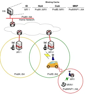
Figure 1: NEMO Basic Support protocol operation overview.
network, the mobile network nodes (MNNs) use IP addresses that belong to one or more address blocks assigned to the home network: the mobile network prefixes (MNPs). These addresses remain assigned to the NEMO even when it is away from home3
. Thus, when the NEMO is attached to another network, packets addressed to the mobile network nodes will still be routed to the home network, and redirected by the home agent (HA) to the current location of the MR. When the NEMO is connected to a visited network, the MR acquires an address from the visited network, called the care-of address (CoA), where the routing architecture can deliver packets without any additional mechanism (see Figure 1).
3
2.3. Commonly found procedures in VANET solutions
Vehicular Ad-hoc Networks are a particular kind of mobile ad-hoc net-works, characterized by high mobility of nodes, short-lived links and unstruc-tured nature. VANETs are very dynamic and lack a pre-established topology, operating in a fully distributed way without control nor monitoring from a centralized entity. This makes more complex to define solutions for vehic-ular protocols, as there are many different variables defining the nature of VANETs. They can be very dense, as in a urban area, or very sparse, as in a remote highway, and these conditions can vary in a few minutes. Moreover, the protocols designed for VANETs have to provide communications with reliability and deal with different sources of interference.
These particular characteristics of VANETs have fostered the publication of routing protocols tailored for them. These protocols adapt the mecha-nisms in ad-hoc networking to the vehicular environment and the mobility patterns of vehicles. In this section, we review the main mechanisms com-monly present in VANET protocols and match them to their equivalent in VARON. Some of these mechanisms were not included in the original def-inition of VARON, but added as found necessary during our experimental process, as described in Section 5.2. The main procedures commonly found in VANET solutions are identified next:
be less effective, establishing a trade-off between signaling overload and effectiveness of the mechanism.
Reliable signaling. After performing the node discovery, multi-hop ad-hoc protocols may use signaling messages to set up paths between selected nodes. This signaling may have different scopes, may be mul-ticast or unicast and can be sent at different rates. Reliable delivery is critical as signaling often involves creating or updating the protocol state. VANET solutions might make use of confirmations or acknowl-edgments to make an involved network node aware of potential failures, and avoid in this way state inconsistency in the network.
Use of cellular communication. A cellular communication channel is sometimes present in the VANET scenario as a reliable always-on connection, providing backup to the unstable ad-hoc network. Many solutions transfer critical or time-constrained information via the cel-lular access network. Interestingly, this celcel-lular connection has been one of the main causes of failure in our experiments, having consider-able packet losses and very variconsider-able delay. Therefore, we claim that this common assumption on the reliability of the cellular connection cannot be taken for granted in real world scenarios.
Mechanisms to deal with link quality variability. The existence of a symmetric communications channel is also often assumed when designing a VANET protocol. However, VANETs conditions are very dynamic, and the reception of a message from a node cannot translate into a subsequent successfully transmission on the way back. Moreover, the use of multicast and unicast signaling messages, which may be sent at different rates in the WLAN, impose different transmission distance ranges. In addition, in the real world, the communication range and the link quality are affected by many different and variable factors, such as vehicles’ speed, taller vehicles passing by or just the weather conditions. Link conditions impact strongly the lifetime of a multi-hop route and therefore, it becomes essential to monitor link status in order to maintain the communications quality for as much time as possible.
2.3.1. VARON: a VANET solution for NEMO route optimization
(VARON). The interested reader is referred to the original design of VARON [1] for further details. Note that the present article introduces some modifica-tions to the original design, based on the key knowledge acquired by imple-menting a real prototype, as it will be described in the next sections.
VARON enables the optimization of vehicle-to-vehicle communications in a secure way by combining a network mobility approach – that supports vehicle-to-Internet communications via the 3G interface – and a vehicular ad-hoc approach – used when a multi-hop network becomes available (i.e., communication takes place between vehicles that are close enough to com-municate through a VANET formed by the mobile routers deployed within those vehicles, and perhaps within other vehicles in their surroundings). We do not consider intra-vehicle communications, as we manage the mobile net-work as a whole, represented by the entity of the mobile router. The route optimization process takes place as follows:
1. Self-organization and discovery of reachable networks. Each mobile
router needs to find out which other MRs are available within the VANET, that is, which mobile network prefixes (MNPs) are reach-able through its ad-hoc interface. To that purpose, every MR pe-riodically broadcasts a message called Home Address Advertisement
(HoAA), which contains its home address and an associated lifetime. These messages are announced through the ad-hoc interface using a hop-limited flooding, so every MR becomes aware of the MNPs that can be reached through the VANET. This mechanism makes a node visible to other nodes potentially interested in establishing a direct communication through the VANET. In our case, in order to avoid missing optimization opportunities and not to flood the network with signaling, these messages are sent at a configurable interval, which was set to 10 seconds in our experiments4.
2. Reliable signaling for the creation and validation of a secure ad-hoc
route. The ad-hoc routing protocol should at least provide the same
security level than today’s Internet communication. The mechanism used by VARON to set up and maintain a secure ad-hoc route is based on [4], modified and extended to fulfill the requirements of a network mobility-based vehicular scenario:
4
First, once a mobile router has identified an optimization oppor-tunity, this MR (called originator MR) has to trigger the ad-hoc route setup by sending to its one-hop neighbors a Care-of Route
Test Init (CoRTI) message. This message is re-broadcast by
inter-mediate routers using a limited flooding until the message reaches its final destination, which is the mobile router handling the target prefix (called target MR).
Second, the target MR generates a reply message called
Care-of Route Test (CoRT) message, and unicasts it back to the MR
that triggered the procedure. Note that the route used to deliver the CoRT message is learned by the intermediate mobile routers during the limited flooding of the CoRTI message, and that the reverse route is learned while delivering the CoRT message. Third, this new bi-directional ad-hoc route (called care-of route) cannot be used yet to forward packets between the mobile net-works managed by the originator and target MRs, as authoriza-tion from the MRs handling those prefixes needs to be verified. This requires exchanging some additional messages, called Home
Route Test (HoRT), using the default NEMO route through the
3G interface (called home route), and some final messages, called
Mobile Network Prefix Binding Update (MNPBU), through the
VANET.
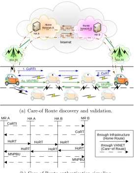
VARON signaling is secured using cryptographic mechanisms, as ex-tensively explained in [1]. Figure 2 shows a simplified example of the route optimization process.
(a) Care-of Route discovery and validation.
MR A MR B
CoRTI
CoRT
HoRT
HoRT
MNPBU
through Infrastructure (Home Route)
through VANET (Care−of Route)
HA A HA B
HoRT
HoRT HoRT
HoRT
MNPBU
(b) Care-of Route authentication signaling.
Figure 2: VARON signaling.
quality is not good enough. In this way, we deal with the link quality vari-ability that may cause a failure in the optimization process or the creation of routes that can be used for a very short period of time (which make them practically useless).
MR A to MR B, and detects that the link to the next hop in the path (MR B itself) is broken, then MR Y sends a CoRE message towards the source (MR A). This message is received by MR X and forwarded to MR A, who notifies MR B the withdrawal of the care-of route with a CoRE message sent through the Internet connection. Then, MR A and MR B switch back to the home route, though they may start a new route discovery procedure to set up an optimized care-of route within the VANET.
Due to the link quality variability commonly found in VANETs and the need to deal with several sources of interference, it is very important to continuously monitor the link quality. As soon as a quality degradation is detected, the optimized route is withdrawn and all the communications take place via the cellular interface. A significant part of our experiments focused on the configuration of the most adequate link quality thresholds, both to establish a multi-hop route in the VANET and to withdraw this route, falling back to the default Internet connection. The design of these thresholds is extremely important in order to avoid short-lived routes, which additionally incur in useless signaling overhead in the network, that might also disturb other users’ communications.
Some of the aforementioned mechanisms are included in our implemen-tation as a result of the experimental learning process, as we will explain in more detail in Section 5.2.
3. Related Work
Research on vehicular communications has extensively addressed many different aspects, from routing protocol design to location privacy or peer-to-peer file sharing. So far, only a minority of the existing research includes experimental results, due to the considerable challenges posed by real-life experimentation.
In order to minimize the costs required to deploy a stable experimental platform, some renowned institutions have opted for deploying their own ve-hicular testbed. This is the case of the Campus Veve-hicular testbed at UCLA or
C-Vet [5], a comprehensive testbed deployment open to external researchers
too, the VanLan testbed at Microsoft campus in Redmond [6] formed of eleven APs distributed all over the campus and two vans equipped with mo-bile nodes, or DieselNet and UMass DOME testbed at Amherst5 [7]. The
5
deployment of a stable vehicular testbed makes possible to run experiments frequently, to evaluate and compare networking protocols as well as to design models for mobility and traffic patterns validation, among many other ap-plications. However, these platforms focus on single-hop V2I communication scenarios, not looking into multi-hop V2V/V2I communications, such as the ones considered by VARON.
A more moderate and frequent approach present in the literature is the use of a wireless network infrastructure already deployed, and roam around in order to assess your own vehicular networking protocol or put network per-formance to the test. In this way, researchers may extract significant insights from real-world experiments at a lower implementation cost. For example, Deshpande et al. [8], benefit from a metro-scale WiFi deployment provided by an ISP to download files during test drivings of different length; and Gi-annoulis et al. [9] focus on the evaluation of channel quality and design an AP quality scoring mechanism to evaluate WiFi performance in the vehicu-lar environment, thanks to the urban wireless mesh network deployed by the TFA (Technology For All) in Houston in cooperation with Rice university6. Following this approach, most of the existing works in the literature are centered on delivering data to or from moving vehicles by means of WiFi APs opportunistically accessed along their way. Cabernet [10] has been de-ployed in 10 taxis in Boston and presents a transport protocol to avoid the shortcomings of TCP when dealing with 802.11 networks and a scanning mechanism to reduce delay in the wireless association process. Note that in VARON, ongoing communications are not delayed by the latency in the wire-less association, as data is being transferred by the cellular connection. Note also that authors in [10] implement timeout optimizations to avoid losses. Similarly, VARON switches to using the WLAN route only if the network is reliable. In relation to that, several works study the most appropriate handoff technique and try to predict WiFi connectivity to avoid losses in the data transfers from or to a vehicle, but very few tackle the issue of vehicle to vehicle communications. Authors in [11] measure packet delivery ratio and packet inter-arrival time between vehicles that travel together in a 960-km long test drive. However, their measurements base on the transmission of beacons and their successful reception, whereas we look for a more general solution. ViFi [12], tested in VanLan and DieselNet, modifies the wireless
6
driver to evaluate different handoff strategies in an ad-hoc network and im-plements a relaying mechanism with a main AP (namely the anchor) and several auxiliary APs to forward data to its final destination. However, this mechanism can only operate in a deployment where all the access points are working on the same channel and requires vehicles to send beacons at regular intervals. In addition, they evaluate different handover strategies, based on RSSI, beacon reception ratio and performance history. These last two mech-anisms cannot be adopted by VARON, since in a wireless ad-hoc network not all the nodes are sending beacons nor is feasible to maintain a history record of performance. Based on that, we concluded that RSSI monitoring was the only possible choice.
Authors in [13] also play with the 3G-WiFi interaction and present Wif-fler, which postpones transmission of delay-tolerant data to the availability of a stable WiFi connection and switches back to 3G if the packet cannot be transmitted fast. This approach uses WiFi as an auxiliary tool for improving 3G transmission and avoids switching to 802.11 unless it can provide quality communications. However, the offload of the cellular connection translates into delaying transmission of non-critical applications, which may not satisfy the user. VARON switches from 3G connection to a wireless multi-hop ad-hoc route between neighboring vehicles, taking advantage of the locality of communication end-points. Moreover, a potential enhancement considered for future work is to offload some flows, instead of all the traffic, from one route to the other, taking into account traffic characteristics and mobility patterns. In a similar way, authors in [14] present a network stack, CafNet, which lets the application decide which data to send when a WiFi connection becomes available, instead of transmitting “outdated” information buffered by the link layer when there is a connectivity change. Contrarily, VARON does not defer or discard any transmission, but it modifies the routing when the conditions in a wireless multi-hop path are favorable.
In summary, there are recurrent issues in vehicular experimental works: i)
There-fore, keeping track of the signal quality at a certain geographical point is meaningless, since the vehicles may not roam around that point in the future and even in that case, there is no guarantee that the wireless link between them would keep the same conditions.
4. From simulation to the lab: Experiments in a controlled envi-ronment
VARON was initially validated by extensive simulations using OPNET Modeler7. The results showed an impressive performance improvement com-pared to existing approaches. These performance gains appear as a direct result of opportunistically exploiting multi-hop communications via the dy-namic set-up of the VANET. These simulation-based experiments turned out not to fully resemble reality and therefore missed some important aspects of real-life wireless behavior.
In this section we report about the implementation and deployment of a lab-based VARON prototype, as well as the testbed built for its validation and performance assessment.
4.1. Network scenario
In order to experimentally validate VARON in the laboratory, the network scenario presented in Figure 3 was deployed. During this phase (lab tests), all the network elements were physically deployed in a laboratory at the University Carlos III of Madrid. The implementation of each entity and the description of the main elements that are part of the prototype are described next:
The mobile router (MR) is the key element in the VARON prototype. In the initial phase of the experiments, this entity was implemented in an Asus WL-500g Premium router, a low cost device equipped with a 266 MHz CPU and 32 MB of RAM. In spite of its limited capabilities, it was initially selected8 because of its low cost, acceptable performance, the possibility of customizing its firmware according to our needs and, most importantly, the flexibility in terms of potential number of net-work interfaces. The device is equipped with two USB ports that can
7
http://www.opnet.com/solutions/network_rd/modeler.html
8
Figure 3: Complete network and VARON prototype scenario.
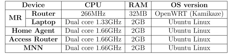
Table 1: HW platform for the different nodes in the network.
Device CPU RAM OS version
MR Router 266MHz 32MB OpenWRT (Kamikaze)
Laptop Dual core 1.33GHz 2GB Ubuntu Linux
Home Agent Dual core 1.66GHz 2GB Ubuntu Linux
Access Router Dual core 1.66GHz 2GB Ubuntu Linux
MNN Dual core 1.66GHz 2GB Ubuntu Linux
be used to increase the number of network interfaces, by connecting, e.g., a 3G USB dongle. Being able to deploy a heterogeneous network is essential for the functionality that VARON aims to offer. In addition, we replaced the original miniPCI wireless network card with one using an Atheros family chipset, which also supports the 802.11a mode.
access routers were physically located at the laboratory and, since we used a commercial 3G IPv4-only network, we set up a Virtual Private Network 9
(VPN) over the public Internet to offer IPv6 connectivity between the access routers and the mobile routers.
A USB 3G dongle (Huawei E1752C) was used as the additional network interface providing the mobile network access to the infrastructure in order to reach its home network. The MR used the 3G connectivity to reach an IPv6 access router, via a VPN tunnel that hides the traversal of the public Internet and emulates the direct connection (i.e., one-hop distance) between mobile router and access router.
A mobile network node (MNN) was attached to each mobile router. The role of MNN was played by a netbook. Each of these nodes ac-quires an IPv6 address belonging to the mobile network prefix (MNP) managed by the MR it is attached to.
4.2. Software implementation
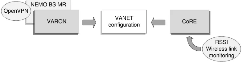
This section is devoted to describing the different software modules of the VARON implementation. The key entity of the prototype is the mobile router, which implements the modules shown in Figure 4.
TheNEMO BS MR module performs the tasks of a mobile router according to the NEMO B.S. protocol: it performs the signaling exchange with the home agent, and configures the bidirectional tunnel used as default data path (home route), keeping the reachability of the mobile network while moving.
TheVARONmodule performs all the signaling defined by the protocol, tak-ing care of setttak-ing up a care-of route and then establishtak-ing a tunnel between the mobile routers involved in the VARON optimization. Once this process is completed, traffic flowing between the mobile nodes managed by the MRs is forwarded through the care-of route, instead of using the default one to the home network through the Internet, with the subsequent delay reduction and bandwidth gain. Both, VARON and NEMO BS MR modules were developed in C.
Given the dynamic environment of vehicular networks, care-of routes may not last for a long time. The original VARON design specified the use of Care-of Route Error (CoRE) messages to signal when a care-Care-of route should not
9
Figure 4: Software modules implemented in the mobile router.
be used anymore. However, the mechanisms that could be used to trigger CoRE signaling were not fully specified in [1]. This is actually one of the aspects of the VARON design that we wanted to analyze in more detail and improve as part of this experimental work. The CoRE module is in charge of monitoring the wireless links used by active care-of routes, in order to avoid packet losses due to insufficient link quality. The ath5k wireless
driver10 used in our prototype provides Received Signal Strength Indication (RSSI) measurements of every node in communication range, which can be used as a metric to detect link quality degradation with the next hop of an optimized (care-of) route. The VARON original design proposed monitoring layer-2 acknowledgments as a possible mechanism to assess link quality but we discarded this mechanism because in our experiments it did not detect quickly enough link quality oscillations. We adopted an approach used by other works found in the literature (see Section 3): to take the RSSI as an indicator of link quality, although its very oscillating nature makes its use very challenging.
VARON internally sets an RSSI threshold: values below this threshold indicate that the communications are likely to fail. VARON monitors the RSSI using a sample-averaging algorithm to avoid frequent switching between an optimized care-of route and the default home route. The sample-averaging algorithm implemented in our prototype is referred to as Weighted Mean of
3 Samples (WM3S) [16], that weights the last three RSSI samples according
to the following formula:
y[n] =α·x[n−2] +β·x[n−1] +γ·x[n] (1)
10
Table 2: Time needed for establishing VARON optimized route.
Care-of route length (hops) Time [ms]
1 549.6 26.5 2 853.5 61.7 3 1166.5 76.4 4 1434.96 47.7 5 1759.8 63.5 6 2055.2 85.1 7 2377.5 97.6 8 2639.4 74.8
The three weights11 are distributed in order to weight more the most recent sample as compared to the rest. The RSSI sampling frequency is a configurable parameter to be able to modify it according to the test running and the kind of traffic.
When the value of y[n] resulting from (1) computed by a mobile router goes below the configured threshold, a CoRE message is sent to the other endpoint of the VARON tunnel through the Internet. The transmission and the reception of this message by an MR automatically withdraw the opti-mized route, falling back to the default route over the Internet.
4.3. Validation in a controlled environment
The first validation and experimental analysis of VARON was conducted indoor, inside a networking lab of our university. As it will be shown later, conclusions obtained from this first validation also have a lot in common with other laboratory-based efforts: observed behavior and performance deviates from the one experienced in a real-life trial.
These initial tests focused on assessing the feasibility of the protocol and validating the prototype, as well as analyzing the impact of the length of the care-of route on the performance in a non-mobile scenario.
The first tests involved only two mobile routers, using also IEEE 802.11 as wireless technology to connect to the fixed infrastructure (instead of 3G), increasing the number of MRs subsequently until reaching a maximum of 9 nodes (i.e., 8 hops). All the nodes were located inside the same room, so there was direct radio connectivity among them. In order to emulate a multi-hop
11
scenario, ip6tables12 was used to limit the reachability of the nodes at the IP layer.
Table 2 shows the time needed to complete the establishment of the care-of route for different number care-of hops. Most care-of that time is spent by the mobile router performing cryptographic operations (using a key size of 512 bits), essential for security enforcement but very time consuming for a device with limited capabilities such as the nodes we used in these tests. Note that during the optimized route setup time, the data connection is never interrupted, as traffic is forwarded using the home route, always available.
5. From the lab into reality: On-road experimentation
In the previous sections we have reported on the initial evaluation efforts of VARON, which started with extensive simulations and continued with an experimental validation in a controlled environment, allowing us to check the correctness of the protocol and serving as a proof of concept of VARON. In many vehicular research works, the experimental analysis stops here, i.e., solutions do not leave the simulator or a controlled-environment laboratory. This article attempts to go beyond this, by proving the feasibility of the mechanisms proposed by VARON under realistic conditions. This section describes the deployment of the vehicular network prototype, the experiments conducted, as well as the main results and the lessons learned from this experience.
5.1. Scenario and testbed deployment
Starting from the VARON prototype evaluated in a laboratory, we fol-lowed an incremental approach to improve and further develop the prototype while validating it under real life conditions13.
Commercial off-the-self (COTS) devices are very convenient in terms of flexibility, cost, and size, but they present limitations due to its processing capabilities and storage capacity, which affect the performance of the pro-totype. For instance, as experienced during our trials, the computing load
12
ip6tablesis a Linux kernel tool that let the user examine and configure the tables of IPv6 packet filter rules.
13
Figure 5: A snapshot of the experimental set up.
needed for handling simultaneously the several interfaces, the VPN connec-tion and the cryptographic operaconnec-tions added significant delay in the process. Moreover, the addition of the 3G USB interface noticeably lowered the per-formance of the COTS device. This led us to upgrade the hardware of mobile routers, wireless cards and antennae. We replaced the router in the field tri-als phase with a laptop capable of easily handling all the processes that run in parallel in the mobile router. The capabilities of the hardware finally used are comparable (or even lower) to the ones of the future in-vehicle deployed communication devices. The laptop was equipped with an 802.11a/b/g Ubiq-uiti SRC wireless card with an MMCX plug for an external antenna at the outdoor testing phase. At the operating frequency and the transmission data rate, the sensitivity of the wireless card is −94dBm±1dB14. Additionally, the communication range of the WLAN link has been enlarged by attaching an omnidirectional antenna working in the range of 5 GHz.
The first round of experiments involved two vehicles, and was aimed at validating the VARON route optimization and evaluating the feasibility of inter-technology handovers. On a second round, another vehicle was added, in order to assess the multi-hop route optimization and estimate the suit-ability of the multi-hop mechanism.
Each of the vehicles (see Figure 5) was fully equipped with a mobile router (a Linux-based laptop) installed on the car’s roof, next to the antenna, while
14
50 m
100ft MR2
MR1
MR3
1
2
3
Figure 6: Test itinerary followed in the Leganes scientific cluster.
the mobile network node (a Linux-based netbook), connected to the MR by Ethernet, is placed inside the car. Both devices are powered by means of an AC/DC adapter.
The selection of a proper scenario for the test drives is an important deci-sion. We chose the Leganes scientific cluster15 because of two main reasons:
i) it presented a relatively low traffic load (to prevent us from obstructing other vehicles), and ii) it had a regular street design, with roundabouts and straight stretches, which is a key point for the repeatability of the experi-ments.
From the very beginning, the design of the experiments took into account
repeatability as one critical requirement. Figure 6 shows the starting position
of each vehicle and the itinerary they followed in the 2-node and 3-node
15
tests16. Each testing round consisted of the following steps:
1. The initial position of the vehicles was such that no direct MR-to-MR connectivity is possible.
2. One vehicle (from now on referred to as MR2) started getting closer to the other vehicle, MR1.
3. When they were close enough to enable WLAN communication, they started the VARON route optimization signaling, which resulted in set-ting up a care-of route if the process ends successfully. Otherwise, the optimization process was aborted, waiting for a new optimization op-portunity. In the case of the 3-vehicle scenario, MR2 initially followed the path enclosed in a box at the bottom of Figure 6. When the link between MR2 and MR3 was broken, the route fell back to the 3G con-nection, until MR2, which continued approaching by the same initial street, was close enough to enable WLAN communication again. 4. Vehicles moved forward together until reaching an intersection
(round-about 2), where they took separate paths, compromising wireless link quality and thus forcing a handover back to the cellular connection at some point in time, triggered by a CoRE message.
5. Vehicles continued on their corresponding designated paths, which led them to meet each other at roundabout 3, enabling the establishment of a care-of route again.
6. They continued towards their initial positions, inducing a second han-dover to the cellular default route.
Therefore, a complete round accounted for two inter-technology han-dovers from the cellular network to the WLAN and another two in the other way. This allowed VARON to recover from an optimization and to confirm that both MRs are able to start a new route optimization, if required. Each test was repeated a minimum of 20 times, both for the single-hop (2-node) and two-hop (3-node) scenarios. The average speed of the vehicles during these tests was 50 km/h.
To detect when to switch from the care-of route to the home route, VARON considers the link quality metric provided by the RSSI. As men-tioned before, the use of RSSI for this purpose is challenging, due to the
16
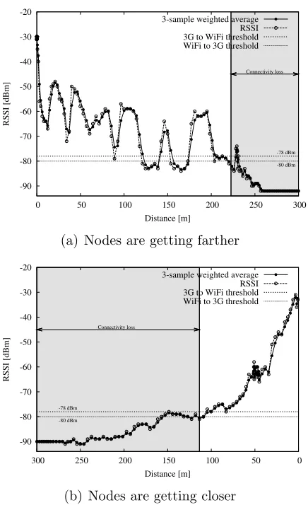
dynamism of VANETs. In order to fine tune our algorithm, we first ana-lyzed how the WLAN RSSI and the connectivity varied with the distance between nodes. We selected the thresholds for triggering the handover from the WLAN to 3G based on these results, which are shown in Figure 7. The gray areas denote lack of WLAN connectivity due to packet losses and errors. Then, we need to anticipate those losses by sending a CoRE message to the two communication ends, as explained in [1] and in Section 2.3.1. Obtained results provide some interesting insights: i) the degradation of the link qual-ity due to the increasing distance between nodes is evident, but ii) distance is not the only determinant factor. For instance, in light of the differences observed in the measurements when the nodes are moving farther or closer to each other, we can claim the importance of their relative positions, the lo-cation of the antennae (i.e., their alignment depends on the actual shape of the car) and the multi-path reception.
5.2. Early testing and implementation feedback
As we will describe next, to fully deploy VARON in a real scenario we had to adjust and improve the original VARON design in order to tackle the different issues we found in the process, which relate to the common VANET mechanisms identified in Section 2.
5.2.1. Effectiveness of the limited flooding
-90 -80 -70 -60 -50 -40 -30 -20
0 50 100 150 200 250 300
RSSI [dBm]
Distance [m]
-78 dBm
-80 dBm Connectivity loss 3-sample weighted average
RSSI 3G to WiFi threshold WiFi to 3G threshold
(a) Nodes are getting farther
-90 -80 -70 -60 -50 -40 -30 -20 0 50 100 150 200 250 300 RSSI [dBm] Distance [m] -78 dBm -80 dBm Connectivity loss
3-sample weighted average RSSI 3G to WiFi threshold WiFi to 3G threshold
(b) Nodes are getting closer
Figure 7: Experimental RSSI degradation due to distance between nodes.
than 10 seconds would be inefficient, as the network conditions could dra-matically change between transmissions, leading to much less stable VANET connections.
5.2.2. Use of timers to ensure optimization state consistency
The wireless medium in the VANET may fail during the route optimiza-tion process, as the radio link quality depends on many factors and does not remain exactly the same under any given conditions. As a consequence, VARON messages may be lost or delayed during the care-of route setup. In order to ensure consistency in the VARON state machine and avoid stale states, a modification of the original VARON design was introduced, consist-ing of the use of timers to deprecate an ongoing optimization attempt.
In order to make more clear the use of timers, we consider next a VARON specific example. With VARON, a mobile router may complete all the opti-mization steps on its side, while the other end does not, for example because the last signaling message to complete the process (an MNPBU) is not re-ceived. It is not possible to know whether the last MNPBU was lost or was not even sent (because the first MNPBU is the one actually lost). Therefore, a timer is set when an originator mobile router sends the first MNPBU. If no reply-MNPBU is received before this timeout expires, then the originator mobile router sends a CoRE message to the target MR, to ensure that the state is consistent (no optimization is in place) at both mobile routers.
5.2.3. Is the cellular connectivity that reliable? The need for the CoRE ACK
Cellular connectivity is often assumed to be reliable and to offer full cov-erage. However, this assumption proved out not to be valid according to our experience in the field. Measured 3G connectivity was variable and unsta-ble, delivering data in bursts very often. Additionally, the available band-width was very much dependent on the location and, in general, lower than claimed by mobile operators, exhibiting also unacceptable delays. By default, VARON routes through the cellular network some signaling messages, such as the CoRE message triggering to stop using an optimized (care-of) route when it does not meet the minimum required quality. However, our on-field experiments showed that 3G connectivity was not as reliable as we would expect from a commercial service, and that sometimes this small signaling message (CoRE) is delayed for a long time or even lost.
receives a CoRE, it has to send back a CoRE ACK message. If the ac-knowledgment is not received within a pre-configured time window, a new CoRE message is sent, to ensure that the other mobile router receives it, and therefore prevent it from using the care-of route anymore. Note that without the CoRE ACK, if the original CoRE message is lost, the resulting routes between the two mobile routers involved would end up being asymmetric – one would use the default home route, while the other would still use the optimized, but likely non-working, care-of route.
5.2.4. Avoiding ping-pong optimization effects and short-lived care-of routes: the use of radio link quality thresholds
In the original VARON design, an optimization attempt was initiated as soon as a mobile router detected that an optimization to a prefix used by an ongoing communication was possible. This basically meant that a CoRTI message was sent upon reception of a HoAA matching a prefix with which there was already an ongoing traffic exchange. However, our experiments showed that it was possible that this HoAA message was received under bad link quality conditions that could not guarantee a successful completion of the route optimization process (for instance, due to the distance between vehicles or the asymmetry of the wireless links). Note also that HoAA mes-sages are broadcast, which has a twofold effect: first, there are no link layer re-transmission mechanisms in place to ensure their reception and secondly, the Modulation and Coding Scheme (MCS) has to be set to the lowest of the Basic Service Set, which limits the distance range covered by the transmis-sion.
Another modification to the original VARON design was introduced to deal with this issue and improve the rate of successful route optimizations: the use ofradio link quality thresholds, based on the RSSI of the different re-ceived signaling messages. A mobile router would not send a CoRTI message if the signal strength towards the transmitter of the corresponding HoAA is not higher than a pre-configured threshold. Analogously, a mobile router would not send a CoRT message if the signal strength towards the transmitter of the corresponding CoRTI message is below this threshold.
threshold, triggering the transmission of a CoRE message, and therefore with-drawing the optimization. In order to further reduce the likeliness of setting up a short-lived optimized route, we introduced the following mechanism. The mobile router keeps monitoring the RSSI from the transmission of the CoRTI message, which initiates an optimization attempt, until the moment of sending the MNPBU, which completes it. If the average signal strength measured in all the signaling messages received from the mobile router used to reach the target MR is not above the previously defined threshold, the route optimization process is aborted.
5.3. Experimental results
In the previous section we have described different improvements to the original VARON design triggered by our implementation experience. We next focus on the actual evaluation of the VARON protocol performance, by presenting the main results and measurements collected during our ex-periments. While doing so, and although we refer to a particular solution (VARON), the obtained results can also be used to evaluate the suitability of some of the most common networking mechanisms for VANETs, such as multi-hop routing, message signaling flooding or access technology hetero-geneity.
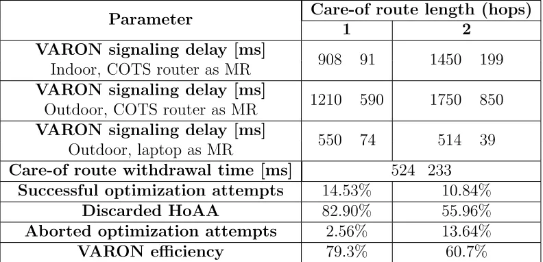
Table 3 summarizes the results for the most representative experiments. A first experiment characterizes the VARON signaling delay, which is the time required to send and process all the VARON protocol messages, set up the required tunnels and forwarding, and configure a care-of route. We performed this experiment both in the lab and outdoors, using 3G connectiv-ity and different hardware choices for the mobile router: the Asus WL500g Premium router and a regular laptop. The results show that the limited resources of the COTS devices impact the route establishment delay, which is considerably shorter when the laptop is used.
Table 3: Experimental results.
Parameter Care-of route length (hops)
1 2
VARON signaling delay [ms]
908 91 1450 199
Indoor, COTS router as MR
VARON signaling delay [ms]
1210 590 1750 850 Outdoor, COTS router as MR
VARON signaling delay [ms]
550 74 514 39
Outdoor, laptop as MR
Care-of route withdrawal time [ms] 524 233
Successful optimization attempts 14.53% 10.84%
Discarded HoAA 82.90% 55.96%
Aborted optimization attempts 2.56% 13.64%
VARON efficiency 79.3% 60.7%
the moment a CoRE ACK is received. Note that since the CoRE and CoRE ACK messages are sent via the 3G interface, the care-of route withdrawal latency is mainly caused by the delay over the 3G network, independently of the number of hops in the care-of route. Figure 8 shows the box-and-whisker plot for these measurements, representing minimum, maximum, median and first and third quantiles for the care-of route set up and withdrawal latencies, for both the single-hop and two-hop scenarios.
! "
! "
Figure 8: Care-of route set up and withdrawal latencies.
confirm the effectiveness of the RSSI threshold that triggers the switch from the home route to the care-of route. Our tests reflect that the route estab-lished by VARON took advantage of the VANET connectivity on average on a 79.3% out the total time with VANET connectivity available for the single-hop scenario, and on a 60.7% for the two-hop scenario.
Table 3 also shows the number of successfully completed VARON opti-mizations, which is quite low because many received HoAAs were simply dis-carded due to its low associated RSSI (note the high percentage of disdis-carded HoAAs). An optimization process may not be completed because the radio link conditions are not good enough, not only at the reception of a HoAA, but also during the whole optimization procedure. It is remarkable that even with this low percentage of completed optimization attempts, VARON achieved a quite high efficiency (around 60-70%). This is actually possible thanks to the use of the RSSI thresholds (not devised in the original design), which avoids attempting to establish a care-of route on a poor-quality wire-less (multi-hop) link. This improvement also contributes to saving useful resources in terms of signaling overhead and energy consumption.
! "#$$% &'()% *#+% *#+$*,% ' - - -
Figure 9: VARON route optimization signaling and data sequence number.
the communication between two mobile networks is using the home (default) route via the 3G network. At some point in time (around t= 20s), a mobile router decides that a route optimization was possible, based on the reception of a HoAA message with good RSSI. This triggered the VARON signaling sequence on the mobile router, which was successfully completed with an MNPBU message (as shown in the bottom close-up, this process took around 0.5s). There was no perceptible interruption in the IP packet flow, as the traffic was being forwarded via the home route until the care-of route has been established. The optimized care-of route was used for more than 70s, until the measured RSSI dropped below the configured threshold, triggering the CoRE - CoRE ACK signaling, which made the mobile routers revert to the home default route. This procedure took also less than 0.5s, as shown in the upper close-up in the figure. Like in the previous care-of route setup procedure, there was no perceptible impact on the IP packet flow.
6. Summary of lessons learned
This section enumerates the most important lessons learned from the im-plementation, deployment and evaluation of VARON. The exercise of bring-ing a vehicular communication protocol into reality has enriched our knowl-edge, directing our attention to very specific issues that may go unnoticed otherwise. We think that these findings are very relevant for the design of successful vehicular networking solutions. We categorize the lessons learned into two groups: those related to the actual deployment of a testbed and a ve-hicular prototype, and those specifically related to the veve-hicular networking protocol.
6.1. Testbed deployment and vehicular prototype 6.1.1. When and where tests should be performed
The location and time for the tests are key elements in the deployment of a real vehicular prototype. The location has to be selected taking into account the safety of the people conducting the tests and the people on the road. As repeatability of the tests is critical in order to achieve statistically meaningful results, the test vehicles may not follow exactly the same behav-ior of a regular vehicle. Similarly, the time of the day has to be carefully chosen, so the impact of undesired external conditions is minimized. Some of these conditions might not be under the control of the people doing the experiments, as for example the quality of the 3G connectivity, which in our case experienced non negligible variations throughout the day.
6.1.2. Selection of the proper hardware
6.1.3. WLAN driver specifics
The design of link layer mechanisms has to take into account the specific hardware and WLAN driver behavior. For instance, the different wireless drivers show different results under the same testing conditions. Node dis-covery and synchronization in ad-hoc mode are specially critical. In our experiments, we adapted our implementation to two different wireless driver implementations, namely madwifi and ath5k as we noticed that the support of ad-hoc mode is quite different from one respect to the other.
6.1.4. Power supply
When performing field trials, a long-live and reliable power source might not be available. This has to be taken into account when selecting the hard-ware, as not all the possible solutions are equally convenient. In our tests, we used both battery-powered uninterruptible power supply (UPS) units and AC/DC inverters plugged to the car to provide power to the nodes. The use of netbooks, which usually present high battery life, is also very convenient.
6.2. Vehicular networking protocol
6.2.1. Multi-hop vs single-hop in the vehicular environment
Vehicular communication protocols may use single- or multi-hop commu-nications. This actually makes a significant difference, because in addition to the obvious routing considerations, there are practical implications. For example, vehicular protocols quite often rely on broadcast or flooding mech-anisms, which do not perform in practice as expected from simulation results (our experiments show low delivery rates of broadcast packets). Special care should be taken when designing a vehicular communication protocol to en-sure that signaling messages meant to traverse a multi-hop network actually reach their destination, and if that is not the case, that there are mechanisms in place to detect it and react accordingly.
Additionally, the implementation of the wireless ad-hoc mode is typically much less developed and debugged as compared to the infrastructure one, which is more widely used. Besides, the differences in ad-hoc mode support and capabilities among the different available hardware and drivers are more disparate than for the case of infrastructure support.
6.2.2. Higher dynamism
environment is very dynamic and suffers from severe radio conditions. This requires a more careful design of the VANET protocols, especially in terms of robustness and redundancy of the signaling. As an example, the reachability of a certain node via a multi-hop VANET route at a given moment does not guarantee that this connectivity will still be there some time after it was tested. Therefore, additional mechanisms should be designed to continuously evaluate this connectivity and detect potential disruptions or situations that indicate a high probability of imminent disconnection.
6.2.3. Cellular networks performance
3G networks are commonly assumed to provide always-on connectivity. Even some proposals make use of 3G networks for the delivery of critical safety messages, as compared to the use of the VANET. However, our exper-iments revealed that 3G may not always be as reliable and stable as expected, but the opposite: measured delay showed great variability, bandwidth fluc-tuated and was often low and there were non-negligible packet loses. This behavior of course depends on the mobile operator and the location, but we believe that roads are particularly prone to suffer from this because opera-tors do not dimension their networks with the goal of providing full 3G data coverage in roads yet. This is likely to change in the future, once mobile data access from vehicles becomes more popular and also when the new cellular technologies, such as LTE, get deployed.
7. Conclusion
Vehicular communications have been extensively researched in the past, with a plethora of different solutions being proposed. However, there is still a lack of experimentation and deployment experience, with some remarkable exceptions of large scale testbed efforts.
With this work, we have tried to fulfill two ambitious goals: i) to experi-mentally validate and evaluate a vehicular communication protocol, VARON, which was initially proposed and extensively simulated in 2008; and ii) to report on the many insights and lessons that we have learned throughout the process of fully implementing VARON and deploying it in a real scenario.
and more importantly, the knowledge acquired from prototyping VARON in this scenario, would also apply to larger testbeds, as the issues we encoun-tered have to be faced by each communicating vehicle individually. In terms of performance, VARON has shown to be feasible, enabling the use of op-portunistically set-up VANET routes between two communicating vehicles, that would have to make use of a cellular network connection otherwise.
While prototyping and experimenting VARON in real vehicles, we had to face and tackle several challenging issues, resulting in some modifications and enhancements to the original VARON design. Additionally, we learned some interesting lessons in this process, that we consider helpful for the vehicular research community, and that we have tried to summarize in this article.
Acknowledgment
The authors would like to thank P. Salvador and F. Giust for their help during the testing phase.
References
[1] C. J. Bernardos, I. Soto, M. Calder´on, F. Boavida, A. Azcorra, Varon: Vehicular ad hoc route optimisation for nemo, Comput. Commun. 30 (2007) 1765–1784.
[2] V. Devarapalli, R. Wakikawa, A. Petrescu, P. Thubert, Network Mobil-ity (NEMO) Basic Support Protocol, RFC 3963 (Proposed Standard), 2005.
[3] C. Perkins, D. Johnson, J. Arkko, Mobility Support in IPv6, RFC 6275, 2011.
[4] K. Sanzgiri, D. LaFlamme, B. Dahill, B. Levine, C. Shields, E. Belding-Royer, Authenticated Routing for Ad hoc Networks, Selected Areas in Communications, IEEE Journal on 23 (2005) 598–610.
[6] R. Mahajan, J. Zahorjan, B. Zill, Understanding wifi-based connectivity from moving vehicles, in: Proceedings of the 7th ACM SIGCOMM conference on Internet measurement, IMC ’07, ACM, New York, NY, USA, 2007, pp. 321–326.
[7] H. Soroush, N. Banerjee, A. Balasubramanian, M. D. Corner, B. N. Levine, B. Lynn, DOME: a diverse outdoor mobile testbed, in: Proceed-ings of the 1st ACM International Workshop on Hot Topics of Planet-Scale Mobility Measurements, HotPlanet ’09, ACM, 2009, pp. 2:1–2:6.
[8] P. Deshpande, X. Hou, S. R. Das, Performance comparison of 3G and metro-scale WiFi for vehicular network access, in: Proceedings of the 10th ACM SIGCOMM conference on Internet measurement, IMC ’10, ACM, New York, NY, USA, 2010, pp. 301–307.
[9] A. Giannoulis, M. Fiore, E. W. Knightly, Supporting vehicular mobil-ity in urban multi-hop wireless networks, in: Proceedings of the 6th international conference on Mobile systems, applications, and services, MobiSys ’08, ACM, New York, NY, USA, 2008, pp. 54–66.
[10] J. Eriksson, H. Balakrishnan, S. Madden, Cabernet: vehicular content delivery using WiFi, in: Proceedings of the 14th ACM international conference on Mobile computing and networking, MobiCom ’08, ACM, New York, NY, USA, 2008, pp. 199–210.
[11] F. Martelli, M. Elena Renda, G. Resta, P. Santi, A measurement-based study of beaconing performance in IEEE 802.11p vehicular networks, in: INFOCOM, 2012 Proceedings IEEE, pp. 1503–1511.
[12] A. Balasubramanian, R. Mahajan, A. Venkataramani, B. N. Levine, J. Zahorjan, Interactive WiFi connectivity for moving vehicles, in: Pro-ceedings of the ACM SIGCOMM 2008 conference on Data communica-tion, SIGCOMM ’08, ACM, New York, NY, USA, 2008, pp. 427–438.
[13] A. Balasubramanian, R. Mahajan, A. Venkataramani, Augmenting mo-bile 3G using WiFi, in: MobiSys ’10: Proceedings of the 8th interna-tional conference on Mobile systems, applications, and services, ACM, 2010, pp. 209–222.
sensor computing system, in: Proceedings of the 4th international con-ference on Embedded networked sensor systems, SenSys ’06, ACM, New York, NY, USA, 2006, pp. 125–138.
[15] P. Deshpande, A. Kashyap, C. Sung, S. R. Das, Predictive methods for improved vehicular WiFi access, in: Proceedings of the 7th international conference on Mobile systems, applications, and services, MobiSys ’09, ACM, 2009, pp. 263–276.
[16] T. Melia, A. de la Oliva, I. Soto, C. Bernardos, A. Vidal, Analysis of the effect of mobile terminal speed on WLAN/3G vertical handovers, in: Global Telecommunications Conference, 2006. GLOBECOM ’06. IEEE, pp. 1 –6.