https://doi.org/10.5194/ms-10-199-2019
© Author(s) 2019. This work is distributed under the Creative Commons Attribution 4.0 License.
Influence of grinding wheel parameters on
the meshing performance of toroidal
surface enveloping conical worm drive
Chongfei Huai and Yaping Zhao
School of Mechanical Engineering and Automation, Northeastern University, Shenyang 110819, China
Correspondence:Yaping Zhao ([email protected])
Received: 1 November 2018 – Revised: 19 April 2019 – Accepted: 23 May 2019 – Published: 11 June 2019
Abstract. A new type of toroidal surface enveloping conical worm gearing is proposed in our recent work (Chongfei and Yaping, 2019b). According to its forming principle, the geometrical shape of the generating surface has an important influence on the geometry characteristic of the enveloping worm pair. To explore the reasonable principles for selecting the geometrical parameters of the grinding wheel, some numerical study examples are performed. In this process, the methods for the tooth crest width are developed. Simple strategies for estimating the risk of the worm tooth surface being located in the invalid area and the risk of the curvature interference on the tooth surface are proposed. The numerical result shows that increasing the radius of the toroidal-generating surface and the nominal pressure angle of the grinding wheel are beneficial to improve the engagement behavior of the conical worm pair, but the tooth crest sharpening of the conical worm may happen if they are too large. For the nominal radius of the grinding wheel, it has a negligible effect on the meshing characteristics of this worm set. In addition, the selection principle of the parameters is also suggested.
1 Introduction
The classical conical worm drive is composed of an Archimedean conical worm and a conical face gear (Litvin, 1997). In line with its forming mechanism, the screw helicoid of the Archimedean conical worm is a ruled surface and is arduous to grind precisely in line with the forming principle (Bohle, 1955; Nelson, 1961). Apparently, it is not conducive to the hardening of the tooth surface after it is shaped, and the further enhancement of the meshing behavior of the conical worm drive is thus limited (Yaping and Xiangwei, 2018).
To overcome the shortcoming mentioned above, a new type of toroidal surface enveloping conical worm gearing is suggested in our recent work (Chongfei and Yaping, 2019b). As shown in Fig. 1, the helical surface of this new type of conical worm is ground by a grinding wheel with the toroidal-generating surface. Meanwhile, the coupled worm wheel is enveloped by a taper hob whose working surface is consistent with that of the obtained conical worm.
From the perspective of forming principles, the shape of the generating torus has an important influence on the
ge-ometry of the tooth surfaces of this new type of enveloping conical worm drive. As is well known, the shapes of the two tooth surfaces in the mesh usually have a very important in-fluence on the meshing quality of the gear (Litvin, 2004). Besides, there is no relevant experience for this new type of conical worm drive. Therefore, it is indispensable to study the geometry of the grinding wheel for the sake of improving the meshing quality of the toroidal surface enveloping con-ical worm gearing and providing a reasonable principle of parameter selection for the production.
Figure 1.Schematic diagram of the toroidal surface enveloping conical worm gearing.
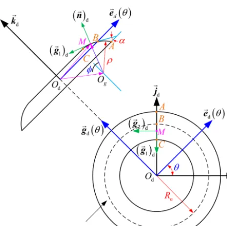
Figure 2.Generating torus of the grinding wheel inσd.
2 Theoretical background
For the numerical simulation study, some relevant theoretical background needs to be briefly introduced in this section.
2.1 Tooth surface equations
As drawn in Fig. 2, a moveable frame σd{Od;id,jd,kd} connected with the grinding wheel is established. For con-venience, the basal vector id is parallel to the end plane of the grinding wheel and passes through the pointB, and the unit vectorkd is along the shaft axis of the abrasion wheel. Then, the vectorjd can be determined by the cross product ofidandkd.
The generating torus on the abrasion wheel intersects with the shaft section of the abrasion wheel along the arc. The pro-jection distance of the pointsAandCin the radial direction of the grinding wheel is set ashf, which is the dedendum of the toroidal surface enveloping conical worm. Inσd, the abscissa and ordinate of the center point of the arc,Og, can be severally represented as (−ρcosα,Rn−ρsinα). Therein, Rn denotes the distance between the original pointOd and the pointCand can be called the nominal radius of the abra-sion wheel,ρrepresents the radius of the arc, andαsignifies the closed angle between the tangent line at the pointC and the end plane of the grinding wheel, which can be called the pressure angle of the grinding-wheel-generating torus. Based on the above, the arc will be determined exclusively when the values ofRn,ρ, andαare given.
In accordance with the geometry site displayed in Fig. 2, the vector equation of the toroidal-generating surface, 6d, may be obtained inσdas
(rd)d= −−→
OdM
d
=−O−−dO→s
d
+−−→OsM
d
=xdid+ydjd+zdkd, (1) where xd=[ρ(sinφ−sinα)+Rn] cosθ, yd= [ρ (sinφ− sinα)+Rn]sinθ, andzd=ρ(cosφ−cosα). Therein, the an-glesθandφare the two curvilinear coordinate parameters of 6d. In theory, any point on6d can be uniquely determined by a set ofθandφ.
By definition (Wardle, 2008), the unit normal vector of6d inσdcan be procured as
(n)d=
∂(rd)d
∂φ ×
∂(rd)d ∂θ
∂(rd)d
∂φ ×
∂(rd)d ∂θ
=nxid+nyjd+nzkd. (2)
vector equation and the unit normal vector of6dcan be ex-pressed in the moving frameσo1as
(rd)o1=
cos (Sπ−γ) 0 sin (Sπ−γ)
0 1 0
−sin (Sπ−γ) 0 cos (Sπ−γ)
xd yd zd
=xodio1+ydjo1+zodko1, (3)
(n)o1=
cos (Sπ−γ) 0 sin (Sπ−γ)
0 1 0
−sin (Sπ−γ) 0 cos (Sπ−γ)
nx ny nz
=noxio1+noyjo1+nozko1, (4)
where xod=xdcos (Sπ−γ)+zdsin (Sπ−γ), zod = −xd sin(Sπ−γ)+zdcos(Sπ−γ), nox =nxcos(Sπ
−γ)+nzsin(Sπ −γ), noy=sinφ sinθ, and noz=
−nxsin (Sπ−γ)+nzcos (Sπ−γ).
The coefficientSis used to distinguish the two sides of the tooth of the conical worm. WhenS=0, Eq. (3) expresses the i flank of the conical worm. WhenS=1, Eq. (3) indicates theeflank of the conical worm.
Next, the tooth equation of the worm helical surface,61(s), can be acquired inσ1as
(r1)1=
cosϕ sinϕ 0
−sinϕ cosϕ 0
0 0 1
xod
ad+poδϕsinδ1+yd poδϕcosδ1+zod
=x1i1+y1j1+z1k1, (5)
where x1=xodcosϕ+(ad+poδϕsinδ1+yd) sinϕ, y1= −xodsinϕ+(ad+poδϕsinδ1+yd) cosϕ, and z1=poδϕcosδ1+zod.
By the literature (Chongfei and Yaping, 2019b), the rel-ative velocity vector of the abrasion wheel and the worm roughcast inσo1can be calculated by
(Vd1)o1=(ωd1)o1×(rd)o1−(ω1)o1×
−−−→
O1Od
o1
=Vd(x1)io1+Vd(y1)jo1+V (z)
d1ko1, (6)
whereVd(x1)=ad+poδϕsinδ1+yd,Vd(y1)=poδsinδ1−xod, andVd(z1)=poδcosδ1.
Based on Eqs. (4) and (6), the meshing function of the abrasion wheel and the conical worm roughcast in the pro-cess of the grinding engagement can be yielded as
8d1=(n)o1· (Vd1)o1=Adϕ+Bd, (7)
where Ad=Ad(φ, θ)=noxpoδsinδ1 and Bd= Bd(φ, θ)=nox(ad+yd)+noyV
(y) d1 +nozV
(y) d1.
In the process of mesh, the equation of the surface family,
n
61(s)o, and its unit normal vector can be deduced inσo∗1as
follows:
r∗1o1=
cosϕ1 −sinϕ1 0 sinϕ1 cosϕ1 0
0 0 1
x1 y1 z1
=x∗o1i∗o1+yo∗1j∗o1+z1k∗o1, 8d(φ, θ, ϕ)=0, (8)
n∗ o1=
cos (ϕ1−ϕ) −sin (ϕ1−ϕ) 0 sin (ϕ1−ϕ) cos (ϕ1−ϕ) 0
0 0 1
nox noy noz
=n∗oxi∗o1+n∗oyj∗o1+nozk∗o1, (9)
wherexo∗1=x1cosϕ1−y1sinϕ1,yo∗1=x1sinϕ1+y1cosϕ1, n∗ox=noxcos (ϕ1−ϕ)−noysin (ϕ1−ϕ), and n∗oy= noxsin(ϕ1−ϕ)+noycos(ϕ1−ϕ).
In line with the method elaborated in the literature (Chongfei and Yaping, 2019b), the relative speed of the worm pair can be obtained inσo1as
(V12)o1=Vxi∗o1+Vyj∗o1+Vzk∗o1, (10)
where Vx= −i1
12
z1+zp+L2w +i12yo∗1
, Vy=xo∗1, and Vz=i1
12 x ∗
o1−a
. Herein,Lw is the actual working length of the conical worm andzpis the axial mounting position of the conical worm.
Based on Eqs. (9) and (10), the mesh function of the toroidal surface enveloping conical worm gearing can be worked out as
812= n∗o1· (V12)o1
=Asin (ϕ1−ϕ)+Bcos (ϕ1−ϕ)+C, (11)
where A=noxVy−noyVx, B=noxVx+noyVy, and C= nozVz.
Via the coordinate transformations, the equation of the conical worm wheel tooth surface can be acquired inσ2as
(r2)2=x2i2+y2j2−y
∗
o1k2, 8d1=0, 812=0, (12)
where x2= xo∗1−acosϕ2−
z1+zp+L2w
sinϕ2 and
y2= xo∗1−asinϕ2+
z1+zp+L2w
cosϕ2.
Correspondingly, whenS=0, Eq. (12) indicates the con-vexity (62(0)) of the worm wheel. WhenS=1, Eq. (12) ex-presses the concavity (62(1)) of the worm wheel.
2.2 Meshing characteristic parameters
forms of6dcan be derived as
E=ρ2, F=0, G=[ρ(sinφ−sinα)+Rn]2, (13) L= −ρ, M=0,
N= −[ρ(sinφ−sinα)+Rn] sinφ. (14) Owing to F =M=0, the two principal curvatures along
g1dand g2dcan, respectively, be acquired as
k1= L
E and k2= N
G. (15)
The basal vectors g1andg2of the frameσMon6d inσo1 can be obtained by the coordinate transformation as follows:
g1
o1=
" cos (Sπ−γ) 0 sin (Sπ−γ)
0 1 0
−sin (Sπ−γ) 0 cos (Sπ−γ)
#
∂(rd)d ∂φ
∂(rd)d ∂φ
=g(ox1)io1+go(y1)jo1+g (z)
o1ko1, (16)
g2
o1= "
cos (Sπ−γ) 0 sin (Sπ−γ)
0 1 0
−sin (Sπ−γ) 0 cos (Sπ−γ)
#
nd× ∂(rd)d
∂φ
∂(rd)d ∂φ
=go(x2)io1+g(oy2)jo1+g (z)
o2ko1, (17)
where g(ox1)=cosφcosθcos (Sπ−γ)−sinφsin (Sπ−γ), go(y1)=cosφsinθ, go(z1)= −cosφcosθsin (Sπ−γ)−sinφ cos (Sπ−γ),g(ox2)= −sinθcos (Sπ −γ),go(y2)=cosθ, and go(z2)=sinθsin(Sπ−γ).
Subsequently, the normal vector,Nd, of the line of contact in the grinding process can be worked out as
(Nd)o1=λd g1
o1+µd g2
o1, (18)
whereλd=k1(Vd1)o1· g1
o1−g
(z)
o2 andµd=k2(Vd1)o1· g1
o1+g (z) o1.
By definition (Litvin, 2004), the curvature interference limit function during the grinding mesh of the enveloping conical worm can be written as
9d=(Nd)o1· (Vd1)o1+Ad. (19) On the basis of Eqs. (16) and (17), the two base vec-tors αξo1 and αηo1 of the moving orthogonal frame σM{OM; αξo1, αηo1,(n∗)o1}can be obtained as
a∗ξ o1
=R[ko1, ϕ1−ϕ] g1
o1,
a∗η o1
=R[ko1, ϕ1−ϕ] g2
o1, (20)
and then the normal vector of the instantaneous contact line in the meshing process of the worm pair can be gained inσM as
(N)o1=Nξ
a∗ξ o1
+Nη
a∗η
o1, (21)
where Nξ=
k1− λ2d 9d
(V12)o1·
a∗ξ o1
−λdµd 9d (V12)o1
·
a∗η o1
+(ω12)o1·
a∗η
o1 and Nη
= −λdµd
9d (V12)o1·
a∗ ξ o1 + k2−
µ2
d 9d
(V12)o1·
a∗
η
o1
−(ω12)o1·
a∗
ξ
o1. By definition (Xuezhu, 1989), the meshing limit function of the worm pair can be represented as
8ϕ1=
∂812 ∂ϕ1
=Acos (ϕ1−ϕ)−Bsin (ϕ1−ϕ). (22)
On the basis of Eqs. (10), (21), (22), and (23), the curvature interference limit function of the conical worm pair can be acquired as
9=Nξ(V12)o1·
a∗ξ o1
+Nη(V12)o1·
a∗η o1
+8ϕ1. (23)
Based on the above calculated results, the induced normal curvaturekN(12)and the sliding angleθvtat the meshing point of the conical worm gearing can be derived as
k(12)N =
Nξ2+Nη2
9 and
θvt=arcsin
9−8ϕ1
(V12)o1
·
(N)o1
. (24)
Generally speaking, the smaller the value ofKN(12), the bet-ter the local meshing characbet-teristics (Johnson, 1985; Xi-aolu and Zhongkai, 1992). The closer the value ofθvt ap-proaches 90◦, the better the forming condition of the EHL
oil film is there (Xuezhu, 1989; Yaping and Xiangwei, 2018a; Chongfei, 2019).
3 Numerical simulation study
3.1 Qualitative analysis of variation of parametersρ,α
andRn
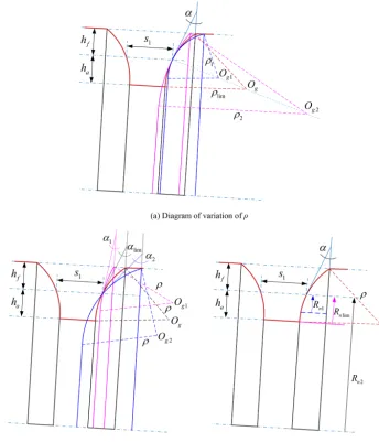
The geometric representation to display the effects of the ra-dius of the generating toroidal surface on the worm tooth shape is given in Fig. 3a. Therein,ρ1< ρlim< ρ2. It is ob-vious that whenρincreases, the tooth crest width and tooth root width of the conical worm both decrease. In particu-lar,ρlim denotes the minimum limiting value of the radius of the generating toroidal surface, and it can be derived as ρlim=ha/sinα. This means that if the radius of the generat-ing toroidal surface is less thanρlimwhen the parametersRn andαare constant, the whole helicoid of the conical worm blank will be ground incompletely.
Figure 3.Geometric representation of the variation of the grinding wheel geometry parameters.
grinding wheel, and it can be derived asαlim=arcsin(ha/ρ). It means that if the nominal pressure angle is less thanαlim when the parameters Rn andρ are constant, the helicoid of the conical worm blank cannot be ground completely.
As shown in Fig. 3c, it can be found that the variation of the nominal radius of the grinding wheel,Rn, has no effect on the geometrical shape of the conical worm tooth. But the value ofRnshould be bigger than that ofRnlim, whereRnlim
is the minimum limiting value of the nominal radius of the grinding wheel andRnlim=ha.
3.2 Basic parameters
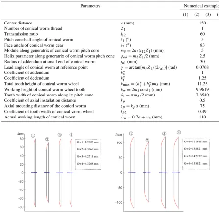
On the basis of the presented theoretical background in Sect. 2, four representative numerical examples labeled (1), (2), (3) and (4), respectively, are provided to investigate the influence of grinding wheel parameters on the meshing
char-acteristics of the toroidal surface enveloping conical worm drive. Among them, Examples (1) and (4) are used to re-search the influence of the nominal pressure angle of the abrasion wheel, Examples (2) and (4) are used to study the effects of the nominal radius of the grinding wheel, and Ex-amples (3) and (4) are used to research the influence of the radius of the toroidal-generating surface. The main parame-ters, which include the technical parameters of the toroidal surface enveloping conical worm pairs and the geometrical parameters of the abrasion wheel, are listed in Tables 1 and 2. In general, coefficientskp andkb2should be selected as small as possible to reduce the size of the worm gear set.
Table 1.Parameters of the conical worm drive in each numerical example.
Parameters Numerical examples
(1) (2) (3) (4)
Center distance a(mm) 150
Number of conical worm thread Z1 1
Transmission ratio i12 60
Pitch cone half angle of conical worm δ1(◦) 5
Face angle of conical worm gear δ2(◦) 83
Module along generatrix of conical worm pitch cone mδ=2a/(i12Z1) (mm) 5
Helix parameter along generatrix of conical worm pitch cone poδ=mδZ1/2 (mm) 2.5
Radius of addendum at small end of conical worm ra1(mm) 30
Lead angle of conical worm at reference point γ=arctan[mδZ1/(2ra1)](rad) 0.0768
Coefficient of addendum h∗a 1
Coefficient of dedendum h∗f 1.25
Total tooth height of conical worm wheel hmax=(h∗a+h∗f)mδ(mm) 11.25 Working height of conical worm wheel tooth hw=2mδcosδ1(mm) 9.9619
Tooth width of conical worm along its pitch cone S1=π mδ/2 (mm) 7.8540
Coefficient of axial installation distance kp 0.5
Axial mounting distance of the conical worm zp=kpa(mm) 75
Coefficient of tooth width of conical worm wheel kb2 0.49
Actual working length of conical worm Lw=0.7a+mδ(mm) 110
Figure 4.Grinding wheel in the shaft section.
in the thickness of the abrasion wheel, while the increasing of the nominal radius of the grinding wheel has no influence on the thickness of the grinding wheel.
3.3 Influence of the grinding wheel parameters on tooth crest width of the toroidal surface enveloping conical worm
Generally speaking, the tooth crest width of the worm can be calculated by solving a series of nonlinear equations (Xuezhu, 1987). But objectively speaking, solving nonlin-ear equations is usually a cumbersome process. In this work, a method is used without solving the nonlinear equations
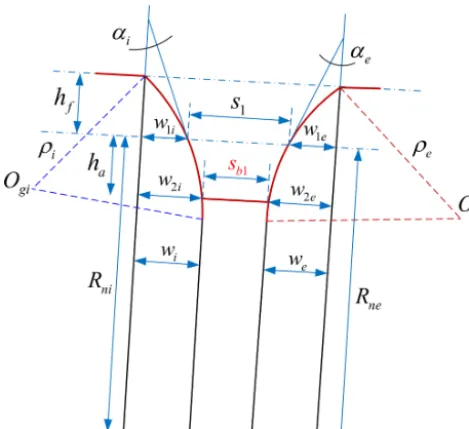
and just according to the geometric relationship between the grinding wheels corresponding to the two sides of the conical worm tooth. According to the geometric positional relation-ship shown in Fig. 5, the tooth crest width of the toroidal surface enveloping conical worm,sb1, can be derived as
sb1=s1+w1e+w1i−w2e−w2i, (25)
where w1i= q
ρi2−(Rni−fi)2−1i, w2i= q
ρi2−(ρisinαi−ha)2−1i, w1e= q
ρ2
e−(Rne−fe)2− 1e,w2e=
q ρ2
e−(ρesinαe−ha)2−1e,1i=h ρihf
Figure 5.Geometric representation of the worm tooth widthsb1.
(hf+ρisinαi)
r
ρi hf
hf+ρisinαi
−h2f
hf , and 1e=
ρehf
hf+ρesinαe+ (hf+ρesinαe)
r
ρe h
f
hf+ρesinαe
−h2
f
hf .
The values ofsb1andKs calculated by the method illus-trated in the reference (Chongfei and Yaping, 2019b) and by the method suggested above are all provided in Table 3. It is easy to know that the grinding wheel radius has a negligi-ble influence on the tooth crest width of the toroidal surface enveloping conical worm. However, reducing the value ofρ andαcan increase the crest thickness of the conical worm tooth. Obviously, these laws of influence are consistent with the trends reflected in Fig. 3. Besides, the error in the value of sb1calculated by the two methods is minor, and it means that Eq. (26) is effective. The reason for the error is that the profile curves of the worm tooth and the grinding-wheel-generating surface are close but not identical in the axial section.
3.4 Effects of grinding wheel parameters on the distribution of the meshing limit line
In line with the meshing theory (Litvin, 2004; Xuezhu, 1989), the meshing limit line will divide the whole helical surface of the worm into an active zone and an inactive zone if it exists on the tooth surface. For the conical worm pair, the whole worm tooth surface has the risk of being in the inac-tive zone since the conical worm is offset to one side of the mating worm wheel. Therefore, it is of great significance to discover the influence of process parameters on the distribu-tion of the meshing limit line.
Based on Eqs. (5), (7), (11), and (22), the meshing limit line on the tooth surface of the conical worm can be
deter-mined by the following equations:
(r1)1=x1i1+y1j1+zo1k1,
8d1=0, 812=0, 8ϕ1 =0. (26)
Combining the third and fourth equations of Eq. (26) by eliminating the angleϕ1yields
fML(φ, θ, ϕ)=A2+B2−C2=0. (27) In general, giving the abscissa of the points on the mesh-ing limit line and based on Eq. (27), the parameters of these points can be acquired. Based on this, the meshing limit line can thus be determined, and then we can judge whether the meshing zone of the worm gearing is effective or not, while in fact the question of whether the conjugate area is effective actually is whether the angleϕ1 has a real solution in this zone. If the real solution ofϕ1 exists, the meshing zone is valid; otherwise, it is invalid.
By letting812=0, the analytical solution of the angleϕ1 can be obtained as
ϕ1=ϕ1(φ, θ, ϕ)=ϕ−ϕ0−arcsin
C/pA2+B2; (28)
in particular,ϕ0is an aided angle, and it can be ascertained by sinϕ0=B/
√
A2+B2and cosϕ 0=A/
√
A2+B2. From Eq. (28), it can be found that the necessary condi-tion forϕ1to have a real solution is
C/
√
A2+B2 ≤1. As
is well known, on the meshing limit line, C/
√
A2+B2 ≡1
(Yaping et al., 2010, 2011, 2017). Therefore, the value of
C/
√
A2+B2
at any meshing point in the valid
engage-ment zone should be in the interval of 0 to 1. For the sake of simplicity, we can define the predictive coefficientkML=
C/
√
A2+B2
, which can be used to predict whether the
re-lated inspection point is within the engagement zone and to assess the degree of risk of the meshing limit line entering the meshing zone. Concretely, the closer the value ofkMLat the inspection point is to 1, the closer the point is to the meshing limit line. If the value ofkMLat the related inspection point is greater than 1, it can be predicted that this point is in the invalid area and thus cannot participate in meshing. A large number of trial results indicates that the meshing limit line only appears on theeflank of the conical worm tooth sur-face and does not enter theiflank of the worm tooth surface. For brevity, only the values ofkMLat the inspection points along the addendum of theeflank of the conical worm tooth surface are provided in Table 4.
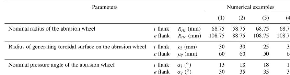
Table 2.Geometric parameters of the abrasion wheel in each numerical example.
Parameters Numerical examples
(1) (2) (3) (4)
Nominal radius of the abrasion wheel iflank Rni(mm) 68.75 58.75 68.75 68.75 eflank Rne(mm) 108.75 88.75 108.75 108.75
Radius of generating toroidal surface on the abrasion wheel iflank ρi(mm) 30 30 25 30
eflank ρe(mm) 60 60 50 60
Nominal pressure angle of the abrasion wheel iflank αi(◦) 13 18 18 18
eflank αe(◦) 30 35 35 35
Table 3.Numerical results of tooth profile parameters in the exam-ples by different methods.
Methods Parameters (1) (2) (3) (4)
The reference sb1(mm) 4.5701 3.6171 3.8810 3.6155 Ks 0.9140 0.7234 0.7762 0.7231
This paper sb1(mm) 4.5540 3.5452 3.6994 3.5452 Ks 0.9108 0.7090 0.7399 0.7090
According to the values of kML at the inspection points in Example (2), it is obvious that the variation of the nominal radius of the grinding wheel has an almost negligible impact on the distribution of the meshing limit line. For Example (3), it indicates that the related inspection points are closer to the meshing limit line compared to Example (4), with the increasing of the radius of the generating torus.
3.5 Effects of grinding wheel parameters on the distribution of the curvature interference limit line From the meshing theory (Litvin, 2004; Xuezhu, 1989), it can be known that the curvature interference limit line may cause the undercutting when it exists on the tooth surface.
In this section, the influence of process parameters on the distribution of the curvature interference limit line in the grinding engagement of the worm will be investigated. Since the helical surface of the conical worm is the enveloping sur-face of the abrasion-wheel-generating sursur-face, the curvature interference (undercutting) may occur on the conical worm helicoid.
By definition, the value of9d should be equal to 0 if the curvature interference limit line exists. When the parameters of the inspection point are determined, we can estimate the distance between this point and this limit line based on the value of9d. The closer the value of 9d is to 0, the closer the point is to this limit line and the higher the risk is of the undercutting occurring on the conical worm helicoid. Based on Eq. (19), the value of9d can be worked out. Since the curvature interference usually does not occur on theiflank,
only the numerical results of9dat the inspection points on the addendum of the wormeflank are provided in Table 5.
From Table 5, it is clear that the curvature interference limit line is closest to the small end and tooth crest of the conical worm; that is to say, the risk of tooth undercutting is highest in there. As reflected by the data in Examples (1) and (4), increasing the nominal pressure angle of the abrasion wheel can drive the curvature interference limit line away from the conical worm tooth surface: this means that the risk of undercutting on the tooth surface of the worm can be re-duced. Comparing Examples (2) and (4), we can find that in-creasing the nominal radius of the abrasion wheel can reduce the risk of curvature interference. The values of9d at the inspection points in Example (3) indicate that reducing the radius of the generating toroidal surface will cause the cur-vature interference limit line to approach the tooth surface of the conical worm compared with that in Example (4).
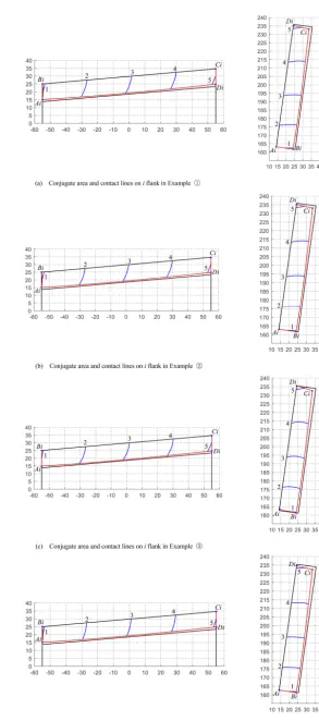
3.6 Effects of grinding wheel parameters on global meshing performance
The meshing zones and the lines of contact on both the i flank andeflank in the numerical examples are displayed in Figs. 6 and 7, respectively. The meshing zones are tagged asAiBiCiDi andAeBeCeDe, and the instantaneous contact lines are numbered as 1, 2, 3, 4, and 5.
Table 4.Values ofkMLat the inspection points on theeflank of the conical worm.
Numerical examples Inspection points
−Lw/2 −Lw/4 0 Lw/4 Lw/2
(1) 0.4393 0.2446 0.1677 0.1273 0.1026
(2) 0.3546 0.2111 0.1500 0.1162 0.0949
(3) 0.3952 0.2270 0.1584 0.1215 0.0985
(4) 0.3545 0.2110 0.1499 0.1161 0.0948
Table 5.Value of9dat the inspection points on theeflank of the conical worm
Numerical examples Inspection points
−Lw/2 −Lw/4 0 Lw/4 Lw/2
(1) −15.9073 −18.0368 −20.2690 −22.6049 −25.0449 (2) −21.5241 −24.5707 −27.7839 −31.1644 −34.7127 (3) −17.2110 −19.5115 −21.9282 −24.4617 −27.1125 (4) −18.7161 −21.2062 −23.8142 −26.5407 −29.3862
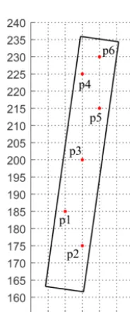
Figure 8.The inspection points selected on the worm gear tooth flank.
3.7 Effects of process parameters on local meshing performance
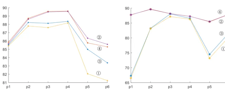
To survey the influence of geometric parameters of a grinding wheel on the local meshing characteristic of conical worm gearing, six points on the tooth flank of a worm wheel are selected randomly as the inspection points. After ascertain-ing these points, the local meshascertain-ing characteristic parameters, such as the induced principal curvaturekN(12)and the sliding angleθvt, can be calculated on the basis of Eq. (24). The line charts of the numerical variation of the two parameters are provided in Figs. 9 and 10.
In line with the data in these tables, the values of k(12)N andθvt, on both thei andeflanks of the worm pair, have not changed significantly with the variation ofRn. While the radius of the toroidal-generating surface,ρ, is increasing, the values of θvt will magnify at the inspection points, which will improve the lubrication performance of the worm gear to some extent. This rule is also applicable when the nominal pressure angle of the grinding wheel,α, is increasing.
4 Conclusions
The mathematical model is constructed for the meshing sim-ulation of the toroidal surface enveloping conical worm gear-ing, whose conical worm helicoid is ground by an abrasion wheel with the toroidal-generating surface.
The qualitative analysis of the variation of grinding wheel parameters is performed. On the basis of the established mathematical model, the numerical simulations are imple-mented. In this process, the method to calculate the worm tooth crest width without solving the nonlinear equations is suggested. The simple strategies for estimating the risk of the worm tooth surface being located in the invalid area and the risk of the curvature interference on the tooth surface are proposed.
The results of the numerical examples study disclose the following.
con-Figure 9.Numerical variation of the induced principal curvature at the observation points.
Figure 10.Numerical variation of the sliding angle at the observation points.
ical worm will be reduced with the increase in the two parameters. Therefore, the values ofαandρshould be limited in a certain scope. Based on a large number of trial results, 15◦≤α≤20◦ is recommended for thei flank and 30◦≤α≤35◦for theeflank. Besides, the pa-rameterρis suggested in the scope of 0.5ra1to 1.5ra1.
2. Though the variation of the nominal radius of the grind-ing wheelRnhas almost no effects on the meshing per-formance of this worm drive, increasing its value can reduce the risk of curvature interference on the worm helicoid. However, in order to save the cost of manufac-turing a grinding wheel, the parameterRnshould not be too large.
Data availability. All the data used in this article can be made available upon reasonable request. Please contact the correspond-ing author (Yapcorrespond-ing Zhao, [email protected]).
Author contributions. CH conducted theoretical calculation and example studies and wrote the manuscript under the guidance of YZ. YZ verified the results and supervised the whole work.
Competing interests. The authors declare that they have no con-flict of interest.
Acknowledgements. The authors acknowledge the open fund of the key laboratory for metallurgical equipment and control of the Ministry of Education in Wuhan University of Science and Technol-ogy (2018B05) and the subsidy from the National Natural Science Foundation of China (51475083).
Review statement. This paper was edited by Bahman Azarhoushang and reviewed by two anonymous referees.
References
Bohle, F.: Conical worm Gears, Mach., 62, 155–161, 1955. Chongfei, H. and Yaping, Z.: Variable height modification of
TA worm drive, P. I. Mech. Eng. C-J. Mec., 233, 227–243, https://doi.org/10.1177/0954406218757269, 2019a.
Chongfei, H. and Yaping, Z.: Meshing theory and tooth profile geometry of toroidal surface enveloping coni-cal worm drive, Mech. Mach. Theory, 134, 476–498, https://doi.org/10.1016/j.mechmachtheory.2019.01.006, 2019b. Johnson, K. L.: Contact Mechanics, Cambridge University Press,
UK, 1985.
Litvin, F. L.: Development of Gear Technology and Theory of Gear-ing, NASA Reference Publication, Cleveland, Ohio, 1997. Litvin, F. L. and Alfonso, F.: Gear Geometry and Applied Theory,
2nd Edn., Cambridge University Press, UK, 2004.
Nelson, W. D.: Conical worm Gearing, Mach. Des., 33, 136–144, 1961.
Wardle, K. L.: Differential Geometry, Dover Publications INC, New York, 2008.
Xiaolu, Z. and Zhongkai, E.: Analysis of load capacity of gears, Higher Education Press, Beijing, 1992.
Xuezhu, D.: Design of Worm Drives, China Machine Press, Beijing, 1987.
Xuezhu, D.: Meshing Theory Foundation of Gearing, China Ma-chine Press, Beijing, 1989.
Yaping, Z. and Xiangwei, K.: Meshing principle of conical surface enveloping conical worm drive, Mech. Mach. Theory, 123, 1–26, https://doi.org/10.1016/j.mechmachtheory.2018.01.012, 2018. Yaping, Z., Daizhong, S., and Zhao, Z.: Meshing analysis and
tech-nological parameters selection of dual tori double-enveloping toroidal worm drive, Mech. Mach. Theory, 45, 1269–1285, https://doi.org/10.1016/j.mechmachtheory.2010.04.004, 2010. Yaping, Z., Jianyi, K., Gongfa, L., and Tianchao, W.: Tooth
flank modification theory of dual-torus double-enveloping hour-glass worm drives, Comput. Aided Des., 43, 1535–1544, https://doi.org/10.1016/j.cad.2011.06.024, 2011.