www.mech-sci.net/2/65/2011/ doi:10.5194/ms-2-65-2011
©Author(s) 2011. CC Attribution 3.0 License.
Mechanical
Sciences
Open Access
Static model for a 3-DOF underactuated finger
F. Guay and C. Gosselin
Laboratoire de robotique, D´epartement de g´enie m´ecanique, Universit´e Laval, Qu´ebec, Canada
Received: 27 February 2010 – Revised: 30 June 2010 – Accepted: 19 August 2010 – Published: 8 February 2011
Abstract. This paper introduces a static model of a three-degree-of-freedom underactuated finger. The model includes all static forces, namely actuation forces, return forces and gravity. All geometric and static param-eters can be freely changed (pulley radius, member’s mass, etc.). Hence, the model allows complete static simulations to be performed and it can also be used for numerical optimization.
This paper was presented at the IFToMM/ASME International Workshop on Underactuated Grasping (UG2010), 19 August 2010, Montr´eal, Canada.
1 Introduction
Governmental investment in prosthetic research has in-creased significantly over the last decade, the most notable initiative being DARPA’s Revolutionizing Prosthetics pro-gram in the US (Belfiore, 2009).
One of the most sought and important criterion is to de-velop a hand that looks and feels natural (Belfiore, 2009). That is the person who wears and uses the prosthesis doesn’t feel out of place in public. This criterion is extremely impor-tant for that the person who is to wear the prosthesis will not prematurely discard it to never wear it again. Therefore, a prosthetic hand should have 5 fingers each including 3 pha-langes.
A possible approach is to develop a hand in which each finger joint is independently actuated. Even with simplifica-tions such as modelling the finger’s joints as revolute joints, this leads to a total of 15 actuators which have to be pow-ered and controlled. The problem encountpow-ered in such an approach is the integration of such a large number of parts, the amount of time and effort for someone who is not likely technically inclined to master and use this complex assembly, the reliability and ruggedness of such an assembly and, often the problem that will be determinant, the combined weight and wearability of such a system.
Therefore, underactuation is a very attractive alternative. Underactuation is the property of a mechanism that has fewer
Correspondence to: F. Guay
degrees of actuation than degrees of freedom. The control of the degrees of freedom is achieved by mechanical intelli-gence.
Several underactuated fingers have been proposed in the literature (see for instance Birglen et al., 2008) for a litera-ture survey). Many of the proposed fingers use tendon-based transmissions and a single degree of actuation. This principle is studied here and a finger model is proposed.
2 The finger model
The model proposed in this article considers the following torque vectors:τa, the actuation which makes the finger curl,
τr, the spring action which makes the finger flex (open),τf,
the friction forces and, an action never considered before, τg, the gravitational forces. τaandτrcannot be completely
specified since we will impose a torque at only one joint of the finger. On the other hand,τf andτgcan be fully specified
for a given configuration of the finger. In order to model the behaviour of the finger, we will combine all four torque vectors. Figure 1 shows the components of these vectors and their position on the finger.
3 Underactuation
We begin by using, as a basis, the underactuation model pro-posed in Birglen et al. (2008); Allen-Demers et al. (2009) and adapt it to a typical finger used in a prosthesis. Here the only adaptation is to realise that our finger has 3 phalanges which are underactuated.
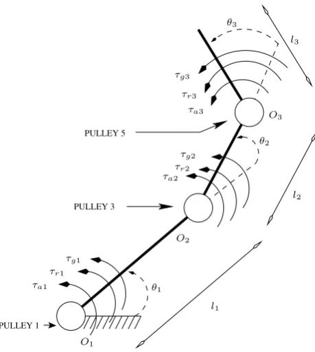
PULLEY 3 PULLEY 5 PULLEY 1 O1 O2 l1 l3 O3 θ2 l2
τa1 τr1
τg1
τa2 τr2
τg2 τa3 τr3 τg3
θ3
θ1
Fig. 1.FINGER WITH CORRESPONDING VARIABLES.
We equate the input and output virtual powers acting on the finger and obtain (Birglen et al., 2008):
tTωa=
3
X
i=1
ξi◦ζi (1)
where t= Ta 0 0
, ωa=
˙ θ1 ˙ θ2 ˙ θ3 ,
ξi=
ωi vx i viy
and ζi=
fti fni τi
tis the vector composed of the input torques applied on the
ithjoint (i = 1,2,3). It is to be understood that joint 1 refers to the joint of the finger linking the latter to the palm of the hand and that joint 3 links the distal phalanx to the medial phalanx.
ωais the vector composed of the angular velocities of the ithjoint (i = 1,2,3).θ˙
ais the angular velocity of the actuation. ξi is the twist associated to the ith point of contact and ζi is the corresponding wrench. They are operated with the reciprocal product,◦in the plane containing the finger. For simplicity, we assume that each phalanx is in contact with the object being grasped and that theithcontact can be con-sidered as a point. The twist is composed of the angular ve-locity, ωi, the velocity components, vxi and v
y
i, of the ith point of contact. These velocity components are in relation
of the local reference frame of theithphalanx. The wrench is composed of the forces acting at theith contact point: a tangential force,fti, a normal force,fni, and a torque,τi.
As shown in (Hunt, 1978), we can defineξi in the follow-ing alternative form:
ξi= i X k=1 ˙ θk 1 ErOk
i
(2)
Here,rOk
i is a vector fromOk to theith point of contact andEis the transformation matrix for a cross product in the plane:
E=
0−1 1 0
(3)
Now, we can express the right-hand side of Eqn. 1 as follows:
3
X
i=1
ξi◦ζi=
3 X i=1 i X k=1 ˙ θk 1 ErOk
i
◦ζi (4)
In this article, we make the assumption that the finger is free of all external forces but the torques needed to obtain static equilibrium. Therefore, the wrench is expressed as:
ζi=
0 0 τi
And Eqn. 4 becomes:
3
X
i=1
ξi◦ζi =
3 X i=1 i X k=1 ˙ θk 1 ErOk
i ◦ 0 0 τi
=τTJ ˙θ (5)
where
J=
1 0 0 1 1 0 1 1 1
Jis a transformation matrix which links the global torques,
τi(i=1,2,3) and the local torques,τi∗(i=1,2,3):
τ∗T=τTJ (6)
τi∗is important since it is the amount of torque felt at theith
joint, i=1,2,3.
Combining Eqns 5, 6 with 1, we get:
tTωa=τTJ ˙θ (7)
=τ∗Tθ˙ (8)
At this point, we defineT, the transmission matrix that re-lates vectorωato vectorθ˙. Explicitly,
˙ θ1 ˙ θ2 ˙ θ3 =
X1 X2X3
0 1 0
0 0 1
˙ θa ˙ θ2 ˙ θ3
Figure 1.Finger with corresponding variables.
We equate the input and output virtual powers acting on the finger and obtain (Birglen et al., 2008):
tTωa=
3
X
i=1
ξi◦ζi (1)
where t= Ta 0 0
, ωa= ˙ θ1 ˙ θ2 ˙ θ3 ,
ξi= ωi vx i vyi
and ζi= fti fni τi
t is the vector composed of the input torques applied on the i-th joint (i=1,2,3). It is to be understood that joint 1 refers to the joint of the finger linking the latter to the palm of the hand and that joint 3 links the distal phalanx to the medial phalanx.ωais the vector composed of the angular velocities
of the i-th joint (i=1,2,3). ˙θais the angular velocity of the
actuation. ξiis the twist associated to the i-th point of
con-tact andζiis the corresponding wrench. They are operated
with the reciprocal product,◦in the plane containing the fin-ger. For simplicity, we assume that each phalanx is in contact with the object being grasped and that the i-th contact can be considered as a point. The twist is composed of the angular velocity,ωi, the velocity components, vxi and vyi, of the i-th
point of contact. These velocity components are in relation
of the local reference frame of the i-th phalanx. The wrench is composed of the forces acting at the i-th contact point: a tangential force, fti, a normal force, fni, and a torque,τi.
As shown in Hunt (1978), we can defineξiin the following
alternative form:
ξi= i X
k=1 ˙ θk
"
1
ErOk
i #
(2)
Here, rOk
i is a vector from Okto the i-th point of contact and E
is the transformation matrix for a cross product in the plane:
E= "
0 −1
1 0
#
(3)
Now, we can express the right-hand side of Eq. (1) as fol-lows:
3
X
i=1 ξi◦ζi=
3
X
i=1
i X
k=1 ˙ θk
"
1
ErOk
i #
◦ζi (4)
In this article, we make the assumption that the finger is free of all external forces but the torques needed to obtain static equilibrium. Therefore, the wrench is expressed as:
ζi= 0 0 τi
And Eq. (4) becomes:
3
X
i=1
ξi◦ζi =
3
X
i=1
i X
k=1 ˙ θk
"
1
ErOk
i # ◦ 0 0 τi
= τTJ˙θ (5)
where J=
1 0 0
1 1 0
1 1 1
J is a transformation matrix which links the global torques,
τi(i=1,2,3) and the local torques,τ∗i (i=1,2,3):
τ∗T=τTJ (6)
τ∗
i is important since it is the amount of torque felt at the i-th
joint, i=1,2,3.
Combining Eqs. (5), (6) with (1), we get:
tTωa = τTJ˙θ (7)
= τ∗Tθ˙
(8)
At this point, we define T, the transmission matrix that re-lates vectorωato vector ˙θ. Explicitly,
˙ θ1 ˙ θ2 ˙ θ3 =
X1 X2 X3
0 1 0
0 0 1
˙ θa ˙ θ2 ˙ θ3
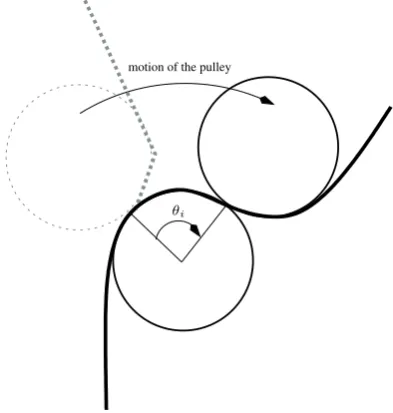
motion of the pulley
θi
Fig. 2.ISOLATED ROTATION OF A JOINT.
or
˙
θ=Tωa (9)
Thus, combining Eqns 8 and 9, we obtain
tTωa=τ∗ T
Tωa (10)
which is equivalent to writing
τ∗=T−Tt (11)
4 Calculation of the Transmission Matrix for the Actu-ation.
In this section, we take a look at the actuation mechanism of the finger. The mechanism consists of a string attached to the distal phalanx. The string is pulled through a pulley net-work which produces the joint actuation. The transmission matrix is the mathematical tool that models the behaviour of the joints.
As stated in the last section, the transmission matrix is the application that transforms the actuation velocity vector,ωa, into the time derivatives of the joints coordinates, Eqn. 9. The main relation to solve is
˙
θ1=X1θ˙a+X2θ˙2+X3θ˙3 (12)
First, as illustrated in Fig. 2, we notice that the isolated rotation of each joint, in joint coordinates, results in an elon-gation of the tendon,xi, of the order of the radius of the joint times the rotation of the same joint:
xi=ria∆θi i= 1,2,3 (13)
In the case of tendon and pulleys, the total amount of elon-gation of the tendon corresponds to the rotation of actuation joint times the radius of joint 1:
x=r1a∆θa (14)
And because we assume that the tendon is rigid, the total amount of elongation is the sum of the elongation for each joint rotation:
x=x1+x2+x3
and by combining Eqns 13 and 14, we obtain
r1a∆θa=r1a∆θ1+r3a∆θ2+r5a∆θ3 (15)
Now, we differentiate Eqn. 15 with respect to time, which gives us
r1aθ˙a=r1aθ˙1+r3aθ˙2+r5aθ˙3
and reorganize in a form similar to Eqn. 12:
r1aθ˙1=r1aθ˙a−r3aθ˙2−r5aθ˙3
or
˙
θ1= ˙θa− r3a r1a ˙ θ2−
r5a r1a ˙
θ3 (16)
So, from Eqn. 16, we can define our transmission matrix for the actuation as the following:
Ta=
1−r3a
r1a −
r5a
r1a
0 1 0
0 0 1
(17)
5 Calculation of the Transmission Matrix for the Re-turn.
We now turn our attention to the return mechanism. Similarly to the actuation mechanism, the return mechanism consists of a string attached to the distal phalanx and passed through a system of pulleys. However, the string is attached to a linear spring a the base of the finger thus providing the return force. As in the case of the actuation, we notice in Fig. 3, that the isolated rotation of each joint, in articulation coordinates, results in an elongation of the tendon,xi, of the order of the radius of the joint times the rotation of the same joint:
xi=rib∆θi i= 1,2,3 (18)
In the case of tendon and pulleys, the total amount of elon-gation of the tendon corresponds to the rotation of actuation joint times the radius of joint 1:
x=r1b∆θa (19)
And because we assume that the tendon is rigid, the total amount of elongation is the sum of the elongation for each joint rotation:
x=x1+x2+x3
Figure 2.Isolated rotation of a joint.
or
˙
θ=Tωa (9)
Thus, combining Eqs. (8) and (9), we obtain
tTωa=τ∗TTωa (10)
which is equivalent to writing
τ∗=T−Tt (11)
4 Calculation of the transmission matrix for the actuation
In this section, we take a look at the actuation mechanism of the finger. The mechanism consists of a string attached to the distal phalanx. The string is pulled through a pulley net-work which produces the joint actuation. The transmission matrix is the mathematical tool that models the behaviour of the joints.
As stated in the last section, the transmission matrix is the application that transforms the actuation velocity vector,ωa,
into the time derivatives of the joints coordinates, Eq. (9). The main relation to solve is
˙
θ1=X1θ˙a+X2θ˙2+X3θ˙3 (12)
First, as illustrated in Fig. 2, we notice that the isolated rotation of each joint, in joint coordinates, results in an elon-gation of the tendon, xi, of the order of the radius of the joint
times the rotation of the same joint:
xi=ria∆θi i=1,2,3 (13)
In the case of tendon and pulleys, the total amount of elon-gation of the tendon corresponds to the rotation of actuation joint times the radius of joint 1:
x=r1a∆θa (14)
And because we assume that the tendon is rigid, the total amount of elongation is the sum of the elongation for each joint rotation:
x=x1+x2+x3
and by combining Eqs. (13) and (14), we obtain
r1a∆θa=r1a∆θ1+r3a∆θ2+r5a∆θ3 (15)
Now, we differentiate Eq. (15) with respect to time, which gives us
r1aθ˙a=r1aθ˙1+r3aθ˙2+r5aθ˙3
and reorganize in a form similar to Eq. (12):
r1aθ˙1=r1aθ˙a−r3aθ˙2−r5aθ˙3
or
˙ θ1=θ˙a−
r3a
r1a ˙ θ2−
r5a
r1a ˙
θ3 (16)
So, from Eq. (16), we can define our transmission matrix for the actuation as the following:
Ta=
1 −r3a
r1a −
r5a
r1a
0 1 0
0 0 1
(17)
5 Calculation of the transmission matrix for the return
We now turn our attention to the return mechanism. Similarly to the actuation mechanism, the return mechanism consists of a string attached to the distal phalanx and passed through a system of pulleys. However, the string is attached to a linear spring a the base of the finger thus providing the return force. As in the case of the actuation, we notice in Fig. 3, that the isolated rotation of each joint, in articulation coordinates, results in an elongation of the tendon, xi, of the order of the
radius of the joint times the rotation of the same joint:
xi=rib∆θi i=1,2,3 (18)
In the case of tendon and pulleys, the total amount of elon-gation of the tendon corresponds to the rotation of actuation joint times the radius of joint 1:
x=r1b∆θa (19)
And because we assume that the tendon is rigid, the total amount of elongation is the sum of the elongation for each joint rotation:
x=x1+x2+x3
change in orientation of the phalanx
θi
Fig. 3.ISOLATED ROTATION OF A JOINT FOR THE RETURN MECHANISM.
and by combining Eqns 18 and 19, we obtain
r1b∆θa=r1b∆θ1+r3b∆θ2+r5b∆θ3 (20)
Now, we differentiate Eqn. 20, which gives us
r1bθ˙a=r1bθ˙1+r3bθ˙2+r5bθ˙3
and reorganize in a form similar to Eqn. 12:
r1bθ˙1=r1bθ˙a−r3bθ˙2−r5bθ˙3
or
˙ θ1= ˙θa−
r3b
r1b
˙ θ2−
r5b
r1b
˙
θ3 (21)
So, from Eqn. 21, we can define our transmission matrix for the return as the following:
Tr=
1−r3b
r1b −
r5b
r1b
0 1 0
0 0 1
(22)
The transmission matrix for the return mechanism is very similar toTafound for the actuation. However, the pulleys
in the return mechanism do not have to be of the same di-mensions used for the pulleys in the actuation mechanism. Therefore, we use here the notation ’b’ to designate a return pulley.
6 Torques from Actuation and Return
In order to find torques due to the underactuated mechanisms, we have found expressions for the transmission matrices. Now we need an expression for the vectortas defined for the use of said vector in Eqn. 1. In the actuation process, its expression is straightforward astais defined as
ta=
Ta
0 0
(23)
where the torque,Ta is the cross product of the tension
put by the user on the string and the radius of the actuation pulley,r1a. The amplitude is expressed as
Ta=Far1a (24)
Using Eqn. 11, we now can get an analytical expression for the torque vector due to the actuation of the finger. This expression is the vector
τa=
Far1a
Far3a
Far5a
(25)
We see with Eqn. 25 that this design has achieved one of its objectives. The actuation torque at each joint is pro-portional to the tension given to the string and the actuation torques are not a function of the finger’s configuration, i.e., they do not depend onθi, i=1,2,3.
In the return process, the vectortris defined in the same
fashion as
t=
Tr
0 0
(26)
where the torque,Tris the cross product of the tension put
by the spring on the string and the radius of the return pulley, r1b. The amplitude is expressed as
Tr=Frr1b (27)
Contrary to the case of actuation, the return force,Fr, is
a straightforward and arbitrary value. To express the return force, we must use Hooke’s law:
Fr=−Ky
where K is the spring’s stiffness and y, its elongation. Since we use preload in this design, an initial extensiony0must be
included in the value of y. The rest of the value of y is taken into account by the elongation caused by the mouvement of the finger which can be described by using Eqn. 20:
y−y0=r1bθ1+r3bθ2+r5bθ3
Figure 3.Isolated rotation of a joint for the return mechanism.
and by combining Eqs. (18) and (19), we obtain
r1b∆θa=r1b∆θ1+r3b∆θ2+r5b∆θ3 (20)
Now, we differentiate Eq. (20), which gives us
r1bθ˙a=r1bθ˙1+r3bθ˙2+r5bθ˙3
and reorganize in a form similar to Eq. (12):
r1bθ˙1=r1bθ˙a−r3bθ˙2−r5bθ˙3
or
˙ θ1=θ˙a−
r3b
r1b ˙ θ2−
r5b
r1b ˙
θ3 (21)
So, from Eq. (21), we can define our transmission matrix for the return as the following:
Tr=
1 −r3b
r1b −
r5b
r1b
0 1 0
0 0 1
(22)
The transmission matrix for the return mechanism is very similar to Ta found for the actuation. However, the pulleys
in the return mechanism do not have to be of the same di-mensions used for the pulleys in the actuation mechanism. Therefore, we use here the notation “b” to designate a return pulley.
6 Torques from actuation and return
In order to find torques due to the underactuated mechanisms, we have found expressions for the transmission matrices. Now we need an expression for the vector t as defined for
the use of said vector in Eq. (1). In the actuation process, its expression is straightforward as tais defined as
ta=
Ta
0 0
(23)
where the torque, Tais the cross product of the tension put by
the user on the string and the radius of the actuation pulley,
r1a. The amplitude is expressed as
Ta=Far1a (24)
Using Eq. (11), we now can get an analytical expression for the torque vector due to the actuation of the finger. This ex-pression is the vector
τa=
Far1a
Far3a
Far5a
(25)
We see with Eq. (25) that this design has achieved one of its objectives. The actuation torque at each joint is proportional to the tension given to the string and the actuation torques are not a function of the finger’s configuration, i.e., they do not depend onθi, i=1,2,3.
In the return process, the vector tris defined in the same
fashion as
t=
Tr
0 0
(26)
where the torque, Tr is the cross product of the tension put
by the spring on the string and the radius of the return pulley,
r1b. The amplitude is expressed as
Tr=Frr1b (27)
Contrary to the case of actuation, the return force, Fr, is a
straightforward and arbitrary value. To express the return force, we must use Hooke’s law:
Fr=−Ky
where K is the spring’s stiffness and y, its elongation. Since we use preload in this design, an initial extension y0must be included in the value of y. The rest of the value of y is taken into account by the elongation caused by the mouvement of the finger which can be described by using Eq. (20):
y−y0=r1bθ1+r3bθ2+r5bθ3
Combining these two expressions, we get a useful expression for the return force:
Fr=−K(y0+r1bθ1+r3bθ2+r5bθ3) (28)
We notice that the negative sign in Eq. (28) accounts for the counter-motion characteristic of the return action.
x y
O1
m2g θ2
O2
θ1 m1g
θ3
m3g
O3 arm tocg3
arm tocg2
arm tocg1
Fig. 4. GRAVITY FORCES DIAGRAM FOR THE PROXIMAL JOINT.
Combining these two expressions, we get a useful expression
for the return force:
F
r=
−K
(
y
0+
r
1bθ
1+
r
3bθ
2+
r
5bθ
3)
(28)
We notice that the negative sign in Eqn. 28 accounts for
the counter-motion characteristic of the return action.
Again, using Eqns. 26, 27 and 28, we now can get an
analytical expression for the torque vector due to the return
action of the finger. This expression is the vector
τ
r=
−Kr
1b(
y
0+
r
1bθ
1+
r
3bθ
2+
r
5bθ
3)
−Kr
3b(
y
0+
r
1bθ
1+
r
3bθ
2+
r
5bθ
3)
−Kr
5b(
y
0+
r
1bθ
1+
r
3bθ
2+
r
5bθ
3)
(29)
7
Gravity
In order to describe the effect of gravity, we must include the
spatial orientation of the hand. For this purpose, we will use
the Tait-Bryan angles which are a specific convention of
Eu-ler angles. These angles correspond to the
XY Z
convention
where
ϕ
is the rotation angle around the
X
-axis,
θ
is the
ro-tation angle around the
Y
-axis and,
ψ
is the rotation angle
around the
Z
-axis.
We assume that the hand is palm up and along the Y-axis.
The origin of the global coordinate system is at the wrist.
This leads to:
–
θ
0expresses the angle formed by the palm and the
Y-axis;
–
θ
1expresses the angle formed by the proximal phalanx
and the extension of the palm;
–
θ
2expresses the angle formed by the medial phalanx
and the extension of the proximal phalanx;
–
θ
3expresses the angle formed by the distal phalanx
and the extension of the medial phalanx;
–
ϕ
expresses the “roll” of the hand (side-to-side
rota-tion).
Now that the hand is spatially oriented, we use the free
body diagram technique to calculate the torques.
We begin to look at the distal phalanx. It is elementary
to see that the resulting torque on the distal joint is the cross
product of the lever arm from the joint to the centre of mass
and the gravity force, the amplitude being
τ
g3= cos(
ϕ
)(
m
3gc
g3cos(
θ
0+
θ
1+
θ
2+
θ
3))
(30)
where
g
is the gravitational acceleration and
m
iis the mass
of the
i
th phalanx. As for the medial joint, the resulting
torque is the sum of the cross products of, on one hand, the
arm created by its centre of mass and the gravity force due
to the mass of the medial phalanx and, on the other hand, the
arm created by its centre of mass and the gravity force due to
the mass of the distal phalanx. The amplitude is
τ
g2= cos(
ϕ
)([
m
2gc
g2cos(
θ
0+
θ
1+
θ
2)]
+ [
m
3g
(
c
g3cos(
θ
0+
θ
1+
θ
2+
θ
3)
+
l
2cos(
θ
0+
θ
1+
θ
2))])
(31)
Finally, for the proximal joint, the resulting torque is the
sum of the cross products of: the arm created by its centre of
mass and the gravity force due to the mass of the proximal
phalanx, the arm created by its centre of mass and the gravity
force due to the mass of the medial phalanx and, the arm
created by its centre of mass and the gravity force due to the
mass of the distal phalanx. The amplitude is
τ
g1= cos(
ϕ
)([
m
1gc
g1cos(
θ
0+
θ
1)]
+ [
m
2g
(
c
g2cos(
θ
0+
θ
1+
θ
2) +
l
1cos(
θ
0+
θ
1))]
+ [
m
3g
(
c
g3cos(
θ
0+
θ
1+
θ
2+
θ
3) +
l
2cos(
θ
0+
θ
1+
θ
2)
+
l
1cos(
θ
0+
θ
1))])
(32)
In summary, the action of gravity can be modeled by
τ
g=
g
CLm
cos
ϕ
(33)
where,
C
=
cos(
θ
0+
θ
1) cos(
θ
0+
θ
1+
θ
2) cos(
θ
0+
θ
1+
θ
2+
θ
3)
0
cos(
θ
0+
θ
1+
θ
2) cos(
θ
0+
θ
1+
θ
2+
θ
3)
0
0
cos(
θ
0+
θ
1+
θ
2+
θ
3)
Figure 4.Gravity forces diagram for the proximal joint.
Again, using Eqs. (26), (27) and (28), we now can get an analytical expression for the torque vector due to the return action of the finger. This expression is the vector
τr=
−Kr1b(y0+r1bθ1+r3bθ2+r5bθ3)
−Kr3b(y0+r1bθ1+r3bθ2+r5bθ3)
−Kr5b(y0+r1bθ1+r3bθ2+r5bθ3)
(29)
7 Gravity
In order to describe the effect of gravity, we must include the spatial orientation of the hand. For this purpose, we will use the Tait-Bryan angles which are a specific convention of Euler angles. These angles correspond to the XYZ conven-tion whereϕis the rotation angle around the x-axis,θis the rotation angle around the y-axis and,ψis the rotation angle around the z-axis.
We assume that the hand is palm up and along the Y-axis. The origin of the global coordinate system is at the wrist. This leads to:
– θ0 expresses the angle formed by the palm and the y-axis;
– θ1expresses the angle formed by the proximal phalanx and the extension of the palm;
– θ2 expresses the angle formed by the medial phalanx and the extension of the proximal phalanx;
– θ3expresses the angle formed by the distal phalanx and the extension of the medial phalanx;
– ϕexpresses the “roll” of the hand (side-to-side rotation).
Now that the hand is spatially oriented, we use the free body diagram technique to calculate the torques.
We begin to look at the distal phalanx. It is elementary to see that the resulting torque on the distal joint is the cross product of the lever arm from the joint to the centre of mass and the gravity force, the amplitude being
τg3 =cos(ϕ)(m3gcg3cos(θ0+θ1+θ2+θ3)) (30)
where g is the gravitational acceleration and miis the mass of
the i-th phalanx. As for the medial joint, the resulting torque is the sum of the cross products of, on one hand, the arm created by its centre of mass and the gravity force due to the mass of the medial phalanx and, on the other hand, the arm created by its centre of mass and the gravity force due to the mass of the distal phalanx. The amplitude is
τg2 = cos(ϕ)([m2gcg2cos(θ0+θ1+θ2)] + [m3g(cg3cos(θ0+θ1+θ2+θ3)
+ l2cos(θ0+θ1+θ2))]) (31)
Finally, Fig. 4 shows that for the proximal joint, the result-ing torque is the sum of the cross products of: the arm created by its centre of mass and the gravity force due to the mass of the proximal phalanx, the arm created by its centre of mass and the gravity force due to the mass of the medial phalanx and, the arm created by its centre of mass and the gravity force due to the mass of the distal phalanx. The amplitude is
τg1 = cos(ϕ)([m1gcg1cos(θ0+θ1)]
+ [m2g(cg2cos(θ0+θ1+θ2)+l1cos(θ0+θ1))] + [m3g(cg3cos(θ0+θ1+θ2+θ3)+l2cos(θ0+θ1+θ2)
+ l1cos(θ0+θ1))]) (32)
In summary, the action of gravity can be modeled by
τg=gCLmcosϕ (33)
where,
C=
cos(θ0+θ1) cos(θ0+θ1+θ2) cos(θ0+θ1+θ2+θ3) 0 cos(θ0+θ1+θ2) cos(θ0+θ1+θ2+θ3)
0 0 cos(θ0+θ1+θ2+θ3)
is the matrix of the finger’s configuration. And,
L=
cg1 l1 l1
0 cg2 l2
0 0 cg3
is the matrix of geometric parameters. And,
m=
m1
m2
m3
is the vector of the phalanx masses. The orientation of the palm is simply determined by the sign of the constant g. As a convention, g is negative for palm up, positive for palm down. We can also eliminate the effect of gravity by setting the gravitational acceleration to 0.
Table 1.Prototype physical parameters.
i ria rib li mi cgi
Proximal 1 6 2.95 45 0.87 21.65 Medial 2 2.75 2.75 25 0.5 9.19
Distal 3 1.5 2 n/a 0.45 10.85
8 The Model
We now have all the pieces of the puzzle. After the develop-ment above, it is natural to conclude that the vector represent-ing the total torque at each joint of the frepresent-inger is the sum of the expressions given in Eqs. (25), (29) and (33). Allen-Demers et al. (2009) shows a similar result.
The torque vector composed of the torque at each joint is expressed as
τ∗=τ
a+τr+τg (34)
If the reader refers to the beginning of this section, there is one component missing from Eq. (34), namely the torque due to friction. Eq. (34) can be used to simulate the overall behaviour of the finger since friction is negligeable for our purposes. But manufacturing affects the amount of friction in the systems, so the torque due to friction must be obtained empirically. So a corrected model can be written as
τ∗=τ
a+τr+τg+τf (35)
9 Numerical simulations
Equation (34) allows the simulation of the behaviour of the finger under arbitrary physical parameters. One can study the behaviour of the finger, more precisely the closing se-quence, according to the stiffness of the return spring, to the imposed preload, to the orientation of the finger (i.e. palm up or down). Another effect of a physical parameter that needs to be studied is the combination of pulleys of different radii and how it affects the closing sequence and ultimately, the grasping force that can be provided.
The numerical software, Matlab, is used to perform nu-merical simulations. Equation (34) is programmed and the physical parameters of the prototype of the finger are in-serted, as shown in Table 1. The routine sets the configu-ration of the finger as being flat, i.e., all angles to be zero. An arbitrary and progressively increasing cable tension is ap-plied and once one of the joints’ torque becomes positive, the variableθiis progressively incremented until the joint angle
is 90◦from its initial position.
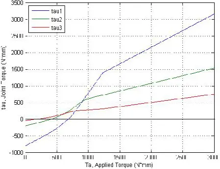
Figure 5 shows the result of this numerical simulation. We first notice that initially, the torques are negative for all three joints. There is no movement since the joints are designed
Figure 5.Closing sequence for the finger prototype.
such that they only move in a positive range of angles. Physi-cally, the range in which the torques are negative corresponds to the situation where the actuation does not overcome the return forces, in this case provided by the return spring and gravity.
We also see that the torque for each joint becomes pos-itive at three distinct points. Furthermore, the torques come positive in numerical order such that joint 1 moves be-fore joint 2 which moves bebe-fore joint 3. This shows that the design attained another of its objectives which is its closing sequence. We have here a closing sequence where the prox-imal joint moves fully through its range of motion then the medial joint moves through its range of motion and then the distal joint moves through its range of motion, all seperately. This simulation is consistent with the physical motion of the prototype whose paramters were used for the simulation.
Figure 6 shows the simulation with a small preload, smaller than 10. We see the same general features that were observed in Fig. 5. However, the negative tension zone is much smaller. This is no surprise since a smaller preload leads to a smaller return force and so a smaller actuation force is needed to overcome the former forces.
Also, we observe that the joint torques still become pos-itive in numerical order. However, the crossing points are very close to each other which suggests a closing sequence that will not follow that crossing order. Multiple joints will move at the same time and so the closing sequence will be uncontrolled.
Finally, Fig. 7 shows a simulation where there is no re-turn. This simulation shows that the closing sequence does not correspond to the design goal. Since there are no return forces and so only gravity forces oppose the actuation, we can see that the distal joint will close first since it is lighter. The proximal joint will be last since it is opposed to the fin-ger’s total mass.
Figure 6.Closing sequence with small preload.
Figure 7.Closing sequence with no return.
10 Conclusions
The model presented in this paper is simple and flexible. It expands the work in Birglen et al. (2008); Allen-Demers et al. (2009) by adapting the equations to the specific case of human-like fingers. It also completes said work by adding the effect of physical forces such as gravity and that, in any spatial orientation of the hand. Furthermore, each force can be easily isolated. Each joint can be also isolated. Hence, the influence of the type of force on a specific joint can be simulated to study its effect along the full range of motion. Each physical parameter is also easily isolated. The effect of combinations of pulley ratios can be easily studied.
This leads to a better understanding and characterisation of the intelligence of the mechanism or of the effect of the return force. Such characterisations can help with the optimisation of the design.
Even though this model was focusing on the internal torques acting on the individual joint, it can be easily ex-tended to external forces. A stability characterisation is needed to see the adaptability of the design.
Acknowledgements. The authors would like to acknowledge the financial support of the Natural Sciences and Engineering Research Council of Canada (NSERC) and of the Canada Research Chair program.
Edited by: J. L. Herder
Reviewed by: two anonymous referees
References
Allen-Demers, L. and Gosselin, C.: Kinematic Design of an Ejection-Free Underactuated Anthropomorphic Finger, Proceed-ings of the 2009 IEEE International Conference on Robotics and Automation, 2009.
Belfiore, M.: The Department of Mad Scientists; How DARPA Is Remaking Our World, from the Internet to Artificial Limbs, Smithsonian Books, New York, NY, 2009.
Birglen, L., Laliberte, T., and Gosselin, C.: Underactuated Robotic Hands, Springer, Berlin, Germany, 2008.
Hunt, K.: Kinematic Geometry of Mechanisms, Oxford University Press, Oxford, England, 1978.