IJSRR, 7(2) April – June, 2018 Page 508
Research article Available online www.ijsrr.org
ISSN: 2279–0543
International Journal of Scientific Research and Reviews
Complete LabVIEW Code for Polarization Shift Keying and Error Correction
Ram Soorat
1, 2, Ashok Vudayagiri
1,*1
School of Physics, University of Hyderabad, Hyderabad 500046, India
2
Department of physics, Indian Institute of Technology, Delhi, India Email: [email protected], [email protected]
ABSTRACT
We report development of an integrated software module using LabVIEW and experimental setup for free space Optical Communication. The transmitter part of this module has in built option for reading a data from a file, convert it into a code to control a pair of diode lasers by switching them on and off. The receiver part of the software measures their polarization state. The protocol also contains hand-shaking, data transmission and also error correction codes which uses Hamming 7-4 protocol.
KEYWORDS:
Polarization Shift Keying, LabVIEW, Handshaking, Hamming code.*Corresponding author
Ashok Vudayagiri
Associate Professor, School of Physics, University of Hyderabad
Hyderabad, India
IJSRR, 7(2) April – June, 2018 Page 509
INTRODUCTION
Optical methods for communication have become increasingly popular because of their large bandwidth and ease of use. However, while most optical methods are based on fiber, a few protocols use free space for long distance optical communication. Such protocols are especially useful in situations when fibers can not be laid, such as earth to satellite links, inter-satellite links or for link between mobile units. Fiber solutions are also superfluous in situations such on-chip connectivity’s. In such situations free space communication are the solutions.
While fibre based protocols preferably use amplitude keying or phase shift keying, Free Space Optical(FSO) protocols can use either of them or in addition also use Polarization Shift Keying (PolSK) as well. This last method involves encoding the message bits with polarization state of a light pulse during transmission. The bits 0 and 1 are respectively mapped to two orthogonal states of polarization. PolSK has several advantages since light can be decomposed into several sets of mutually orthogonal polarizations, such as Vertical/Horizontal, 450/1350or RCP/LCP combinations. In each of this case, the two encodings are mutually orthogonal, in the sense that a light polarized in one state will show zero for measurement for other polarization. This results in an unambiguous measurement, except in presence of noise. This also becomes particularly useful in multi bit per symbol transmission1, although the different basis is not mutually exclusive and hence can provide some ambiguity. But a PolSK method is very robust with respect to measurement and can show high noise tolerances as shown by us in an earlier communication2.
IJSRR, 7(2) April – June, 2018 Page 510
error correction using Hamming code. LabVIEW modules have been developed earlier to specifically work for optical communication. But they are essentially training modules for fibrebased communication or mostly work on Amplitude shift keying6. There has been a published work specifically designed to be used for PoLSK in free space communication7. The code developed by the authors measure a full Stokes Parameters but the code is limited to this measurement, whereas our code is a comprehensive program that involves authentication, handshaking, and error correction protocol.
THE LabVIEW PROGRAM
LabVIEW is a graphical programming interface developed and distributed by National Instruments Inc. USA8,9. This has two distinct advantages over other programing environments (i) the graphicalmethod of programming makes it easier by removing the need to remember the code words, (ii) it hasbuilt-in modules to interface many different types of hardware units and (iii) can create an executable binary version, which can run on a different computer without installing LabVIEW, although this facility is available only on the professional versions. The ease of use and availability of extensive built-in modules has made LabVIEW very popular in case of laboratory automation as well as controlling communication protocol8,9,10. While many of the earlier work uses LabVIEW options to control TCP/IP and built-in communication protocols, we use a control program through DAQ card, which makes the system independent of hardware, i.e., the hardware consisting of diode lasers or APD’s can easily be replaced without any modification of the software.
IJSRR, 7(2) April – June, 2018 Page 511
The code described below is particularly designed for use in our experimental setup. But it can easilybe used for any other schemes as it is, or at best with very little modification. Our setup is described in detail in an earlier communication2 and will be very briefly recounted here for sake of completeness.
THE TRANSMITTER
The transmitter consists of two VCSEL lasers, operating at 780 nm placed about a Polarizing beamsplitter (PBS) as shown in Figure 1.
Figure1. Schematic of the communication setup. Laser 1 and 2 are VCSEL lasers. PBS are polarizing beamsplitters. APD are Avalanche Photo Diode Modules
The lasers and the PBS are arranged in such a way that vertically polarized part of light from laser1 and horizontally polarised part of light from laser 2 are coupled into the communication channel. Thelasers are controlled by the computer through a DAQ card, which in turn fires the laser controller. Laser 1 would be switched on if the message bit is 0 and Laser 2 would be switched on if the message bit is 1.
This would require the LabVIEW code to encode as
Bit Encoding
0
1
01
10
Table 1. Bit encoding
Page 512
The LabVIEW code achieves this by operating a transformation
= 2 →
Wherek is the message bit and the encoded number be as per table above. In addition, a clock pulse,either another VCSEL in case of an all-optical networking, or a pulse transmitted over a wire in caseof a hybrid connection could be used. We have tried both and the same software accounts for either of the method. With the clock pulse, the encoding scheme becomes
Bit Encoding
0
1
no bit
011
101
000
Table 2. Bit encoding with clock pulse
Figure2. Initial module of the transmitter. Generates a random sequence of 0’s and 1’s, converts itinto a relevant format and writes it onto the digital port of the DAQ card using the DAQmx module ofLabVIEW
IJSRR, 7(2) April – June, 2018 Page 513
RECEIVER
The receiver consists of another PBS whose output is incident on two Avalanche Photo Diodes APD1 andAPD2. The APD’s used in our setup was PCD-mini 200 from SenSL. Any other SPC module which operates in Geiger mode and provides TTL pulses for each incident photon would work equally good. The TTL pulses from the APD module are connected to counter pints of the DAQ card NI - PCI - 6320. This card has 4 counter inputs, each with 32 bit resolution and a rate of 25 MHz with external clock. The receiver part of the LabVIEW code is designed to obtain these TTL pulses during the on-time of the clock pulse and total them. The code resets the total number each time the clock pulse is off. This aspect required a certain round about method within the code since the original counter-handling aspect built into the LabVIEW does not contain the reset feature, which is otherwise very important for our protocol.
OPERATION OF THE PROTOCOL
The generic aspects of the protocol is graphically represented in Figure3. As per this, the steps involved are (i) Alice opens up the protocol with a wake up call (ii) Bob acknowledges (iii) Alice asks Bob to identify himself - so as to ensure that the data is given only to authorized receiver. (iii) Bob answers with a pre-agreed ID number. (iv) Alice compares this with the one stored in her computer and if it matches the protocol proceeds.
Figure3. Elements of the protocol Start Protocol
ACK
IDN?
BOB’s ID number
Data Start ACK
Data
End of data
End protocol
ACK
IJSRR, 7(2) April – June, 2018 Page 514
She acknowledges it (v) Then Alice starts a Data Start code and proceeds to transmit all the data. (vi) Bob stores the data on his computer (vii) Alice concludes transmission with an EoD code. (viii) Bob acknowledges receipt of all data (vi) Alice concludes the protocol with End-of-Protocol code.
The corresponding flow chart for the transmitter and receiver are given in Figure4. They represent the steps (i) through (viii) described above.
Figure4. Flowchart of decision making
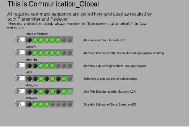
The protocol makes use of a set of standard commands which are used by both Alice and Bob, such ascodes for Acknowledgment (ACK), Start of Data etc. Since these codes are a one-time standard, sharedboth by Alice and Bob, and any other parties involved, we create a set of global variables for thispurpose. The entire set can be shared as it is by all parties. The set of codes are shown in Figure5.
Save data on disk End protocol
End protocol Start
IDN?
Read Bob’s IDN
is Bob’s msg= Bob’s IDN? NO
YES
"Data Start"
Data
"Data End"
Msg from Alice
NO Is MSG = "IDN?"
YES send IDN to Alice
MSG from Alice
Is MSG = "DATA Start?" Start
Recieve Data
Is DATA = "DATA END?" NO
Page 515 Figure5. Front panel of the Global VI, showing all the codes for handshaking
These codes are same for both Alice and Bob, and they pick appropriate global variable from the GlobalVI. A typical set of global codes would look like as in table below.
Mnemonic Binary code Description
Protocol Start
Identify
Data start
ACK
Data size n
Data end
Protocol End
0011 1110
0010 1110
0001 1100
0101 0100
1101 0100
0000 1110
1111 1111
Alice wakes up Bob
Alice asks Bob to identify Bob answers a
pre-approved identity code
Alice tells Bob when data starts. Bob starts
recording data
Acknowledge
n is size of data in kbits
End of Data (by Alice)
Final closing of protocol
Page 516 Figure6. LabVIEW module to transmit theglobal VI codes
Handshake protocols are shown in Figure6. andFigure7. These two modules are for transmission and receiving Figure6.shows the LabVIEW module for the handshake protocol. These modules exchange appropriate words from the Global VI between transmitter and receiver.
Page 517
TRANSMITTER MODULE
The LabVIEW module for transmitter is shown in Figure8. This program reads a binary file from the hard disk and convert it into individual bits for transmission through serial transmission. These bits are then converted into 8 bit word and then sent to write-to-port module of DAQ card.
Figure8. LabVIEW Code to read a binary file, in this case an image and extract individual bits for serial transmission
RECEIVER
The LabVIEW component for the receiver runs on an independent computer, recording data from the two APD modules as shown in schematic 1. The program is started independently of the transmitter program and therefore at the beginning has a waiting loop with continuously analysingsignals received at the input. If the signal corresponds to previously agreed handshaking commands from Alice, only then the program goes to the next step. The all optical version of the module receives and analyses signal. The complete module is shown in Figure9. It contains four subunits, which are described below and shown separately in following Figures for sake of clarity.
Page 518
The first module is shown in Figure 10. The two counters are initialized (top and bottom of the Figure)as well as the received signal is compared for Identify™ code. The identification of Bob is the merelyensure that Alice is transmitting the message to only authorized receiver and not to any one else.
Figure10. First module of the Receiver. It initializes relevant parameters of DAQ and also waitsin a whileloop until it receives an Identifycommand from receiver
As mentioned in previous section, the module is built around NI DAQ card PCI 6320 but in realityuses LabVIEW modules which are hardware independent and hence can be used with any other card withsimilar features. The APD modules provides
Page 519
measurements, the counter will stop reading data when the Samples per Channel have been received. (v) Call the Clear Task VI to clear the Task. (vi) Use the pop-up dialog box to display an error if any.
The program takes input from two APD’s on two counter channels, totals the TTL signals obtainedwithin till the edge detector detects fall of the clock pulses. Since the modules are not equipped with intermittent resetting of the counter, the counts within a clock pulse duration is obtained by subtracting old total from new total. The software also computes ™State of Polarization ™ as given by (1).
= 1− 2
1 + 2 … … . . (1)
APD1,2 indicates counts on respective APD’s within the clock pulse duration. If the value of S is positive, the program assigns data to 1 and if S is negative, the data is assigned to 0. As explained in reference2, this differential method of measurement provides a higher threshold against depolarization noise due to atmospheric effects.
Figure11. Second module of the Receiver. The module sends an acknowledge signal to Alice and proceedsfurther
IJSRR, 7(2) April – June, 2018 Page 520
REEOR CORRECTION USING HAMMING CODE
Hamming code [12] is one of the industry standard algorithms to detect and correct bit flip errors during transmission. The most practical conFigureuration is the (7,4) mode, wherein three parity bits (p1, p2 and p3) are added to four data bits (di, i = 1, 2, 3, 4), adding upto 7 bits.
= ⊕ ⊕ ;
= ⊕ ⊕ ;
= ⊕ ⊕ … … … . (2)
While in normal circumstances the parity bits are computed and interspersed with the data so as tomake a 7 bit word as p1, p2, d1, p3, d2, d3, d4. However,since we started working with random numbers initially, we adopted a method wherein the data are sent at first and the parity bits are computed and transmitted later. This method was particularly adopted for use in a future use of Quantum Key Distribution protocol13 wherein the data bits would be sent through quantum channel while the parity through the classical channel. However, the mathematics related to the computation and use of the syndrome set was identical whether the parity bits were transmitted interspersed with data bits or otherwise.
The LabVIEW code for this part consists of the transmitter part computing the relevant parity bitsand create the Generator matrix G. The receiver code has modules to use this matrix G, identify the error as per standard methods and then correct them. The code follows standard computational method as
=
1 1 0 1 1 1 1 0 1 0 0 0 0 1 1 1 0 1 0 0 0 0 1 0 0 0 0 1
æ è ç ç ç ç ç ç ç ç ç ö ø ÷ ÷ ÷ ÷ ÷ ÷ ÷ ÷ ÷ d1 d2 d3 d4 æ è ç ç ç ç ö ø ÷ ÷ ÷ ÷ ………(3)
Page 521 Figure12. Receiver module of the Hamming correction code to read the generator matrix G and operateit on the
data
Page 522 Figure13. Efficiency of (7,4) Hamming error for a test data. See text for details
A typical run for a data set of about 5000 data bits is shown in Figure13. The Figure13.compares bit error rates before and after running the Hamming error correction code. The straight solid line is representative of the same bit error rate, indicating no effect of error correction. The scatter points are the actual bit error rates for the test data. If the Hamming operation fails to correct the errors, or creates new bit flips instead, the bit error rate after the operation remains same as that before the operation and such a data would lie on the straight line.
It can be seen that most of the runs are below the straight line, indicating that the error rate has indeed been reduced due to the Hamming operation. However, the correction is not very effective when the error rate increases. When error rates are small, the bit error rate after Hamming operation are almost zero - indicating an error correction of very high efficiency. A little around 0.05, corresponding to 5% error rate,the errors after Hamming operation are still significant, even though they are reduced to less than 5%rate. The Figure also shows that there are a few occurrences when the errors are not only not corrected, but actually increased, which is the situation for a few runs that lies about the solid line. As the initial error rates approach 18%, the data appear closer to the solid line, indicating that Hamming operation is almost totally ineffective above this range.
CONCLUSION
IJSRR, 7(2) April – June, 2018 Page 523
to control two diode lasers, each providing light polarized in orthogonal directions, initially mapped to bits 0 and 1. Corresponding light polarization is measured at the receiver, with the help of a Polarizing Beam Splitter (PBS) and a pair of Avalanche Photo diodes (APD). This measurement is in form of a State of Polarization, which takes into account any polarization scrambling during traverse through atmosphere. The differential method adopted provides a higher threshold against noise. The LabVIEW program presented here integrates all these aspects as well as all the relevant handshaking commands. It also includes a (7,4) Hamming code error correction protocol, but with a post process option.
There are two main advantages of LabVIEW- (i) A graphical programing interface with drop downmenus make the task of programing easier. (ii) Simultaneously, many of the required modules such asconnectivity to DAQ cards etc. are already built in and the user has to simply choose the relevant modules. At the same time, it also offers the power of nominal programming such as global/local variables. LabVIEW also allows compiling the code to a stand alone, executable module, which can be run on computers without LabVIEW installed. While there have been many adaptations of the LabVIEW in communication experiments, most of the works presented in literature are of basic modules only. The program presented here consists of a comprehensive protocol, including authentication, handshaking and error correction.
In this program, we have exploited the digital output of a DAQ card to pulse the lasers appropriately for transmitter side and time synchronized counter acquisition to count the pulses from an SPCD moduleon the receiver side. The protocol is completely integrated and contains handshaking protocols as well as the Hamming code for error correction. At the same time, it is also modular so that individual components can be corrected or replaced as required. Full professional versions of LabVIEW also allow creating a stand-alone executable module, which can be run on independent computers. Future goal is to convert the present protocol for embedded versions such as FPGA or Raspberry Pi, which is also allowed by LabVIEW itself.
ACKNOLWDGEMENT
IJSRR, 7(2) April – June, 2018 Page 524
REFERENCESS
1. Benedetto S, Gaudin R,Poggiolini P, Direct Detection of Optical Digital Transmission Based on Polarization Shift Keying Modulation, IEEE J. Sel. Areas in Commun.1995; 13(3): 531. 2. Soorat R, Vudayagiri A,Noise Characterization in Free Space Polarization Modulation
Communication Using Simulated Atmospheric Conditions in Laboratory, Int. J. of Eng.Technical Res. 2014; 2(9), 89.
3. Gutirrez C R and Duelk M, Using LabVIEW™ for advanced nonlinear optoelectronic device simulations in high-speed optical communications, Comp. Phys. Communications, 2006; 174, 431.
4. Sumathi S and Surekha P, LabVIEW based Advanced Instrumentation Systems, Springer, 2007; ISBN:3540485007 9783540485001
5. Cox W.C, Simpson J.A , Domizioli, C.P, Muth J.F. Hughes, B.L, An Underwater Optical Communication System Implementing Reed-Solomon Channel Coding ,IEE, 2008; 978(1): 4244.
6. Online tutorial of National Instruments, Lesson 8 - Free Space Optical Communications, http://www.ni.com/example/13557/en/
7. Ye Yu, Yangan Z, Xueguang Y, Qingxiang H,A LabVIEW-based real-time measurement system for polarization detection and calibration, Optik - Int. J. of Light and Electron Optics,2014; 125: 2256.
8. Lisa K W and Je_rey T, "LabVIEW for everyone: Graphical programming made easier", Prentice Hall, USA, 1996;
9. Chance E, Vipin V, Wesley Z and Richard H, National Instruments LabVIEW: A Programming Environment for Laboratory Automation and Measurement , J of Lab. Automation. 2007; 12: 17.
10.Nie C Y, Xu S and Ji S, Data Acquisition and Realization of Communication Transmission Based on LabVIEW, Int. Conf. on Computer Science and Electronics Engineering (ICC- SEE), 2012; 3, 215-218.
11.Zhengyong L,Lanlan L, Jian W, and Chongqing W, High-speed polarization-shift keying: experimental and numerical investigation, Chin. Opt. let, 2012; 10: 20601.
12.Richard H, Error detecting and error correcting code, The Bell S, Techn. Journal, 1950; 29(2): 147.