Modelling detection of magnetic hysteresis
properties with a microcontroller
Francis T. Omigbodun1, Bankole I. Oladapo2, Oluwole K. Bowoto3, Funso P. Adeyekun4 1,2,3
School of Engineering and Sustainable Development, De Montfort University, Leicester, UK
4
Department of Electrical and Electronics Engineering, Afe Babalola University, Ado Ekiti, Nigeria
Abstract
Equipment properties for human diagnosis and treatment are challenging to acquire because of its high cost. It is necessary to develop resources that can be widely used for medical purposes and also in the industries for the electro muscular disease. This research focuses on measuring the electromagnetic fields in materials, sorting them into different types and knowing their magnetic classification using Fahy Simplex parameter method of described by H-coil can be quickly rotated with a device developed with Arduino Microcontroller. This is to solve the problem of measuring and classifying materials according to their behaviour when subjected to electromagnetic fields. This model design establishes a measure of the degree of hysteresis in articles using a relatively cheap tool and MATLAB for the analysis and Fritzing for the electronic circuit. The research is based on off-shelve hall effect sensors and an Arduino-UNO micro-controller as the interface between the sensor and the material. One of the novelties in this research is the means of attachment of magnetizing force, H, corresponding to points on a hysteresis loop, which attained a high precision as could be obtained for positions on the standard induction curve. By the use of this methodology, a smoother curve is achieved in less time than can be done with the other method.
Keywords: Electromagnetic Fields; Magnetometer; Fahy Simplex parameter; Magnetic field; Degree of hysteresis Introduction
I. INTRODUCTION
The scientific and technical development and technological in physical medicine offer new treatment options in magnetotherapy [1]. The world has experienced exponential growth in all areas of technology in recent time. In this technological revolution, new materials were developed to meet the constant demands for modern products and processes at a lower cost, lightweight, more exceptional durability, of a better performance [2,3]. To meet up with the pace of innovation in medical and biomedical engineering. It is necessary to develop educational resources or device that can be widely used to present the exact sciences to medical and biomedical engineering field such as enhancements in the area of measuring magnetic fields and health. Magnetic materials from its origins play extreme importance in the history of civilizations [3,4]. Their
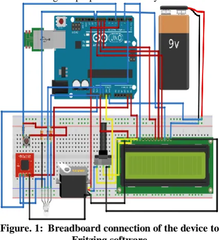
investigate several teaching resources that can support the learning process of magnetism and its applications in industries [16-18]. In this work, the development of a hysteresis-metro using the platform of Arduino microcontroller and sensor, which made it easy enough to understand the interface and help to support learning in institutions, since it operates on a simple software with part of simple plug and plays. Several authors [18,19], pointed out the use of Arduino in designing and developing experimental teaching device for medical, mathematics, programming, physics and the concepts of electromagnetism. The apparatus proposed in this paper was created, as shown in Fig. One on Fritzing and Matlab respectively. In this research, the technologies available in the domestic market were used to ensure low-cost and easy accessibility, without losing the purpose of the study.
Figure. 1: Breadboard connection of the device to Fritzing software
The intention is to design and establish a magnetic-field measuring device using Arduino at this core temperature without generation of heat by the method to disorient the magnetic particles of the materials. The methodology and results presented by researchers [19] were extended over more advanced further analytical techniques of using a 12volt generated device by a computer system connected to the Arduino UNO to produce the necessary voltage needed for the device to run. This reduces heat generated by the device, thereby keeping the arrangement of the particles intact without being disorganized. An open-sourced software Arduino and a commercial one, MATLAB, were used for analytical simulation of the device to determine improvement, accuracy, and reliability of the result obtained. Hence, a low-cost method for magnetic field measurement for medical application to measure the degree of hysteresis, which is easy to operate and control is proposed. The results obtained were satisfying enough to satisfy the objectives of the
research, which make it applicable to the industries and institutions.
II.MATERIALSANDMETHODS
Arduino programming is also available in Arduino IDE software and Fritzing software shown Fig. 1.
1) DESIGNOFSOFTWAREANDCODING
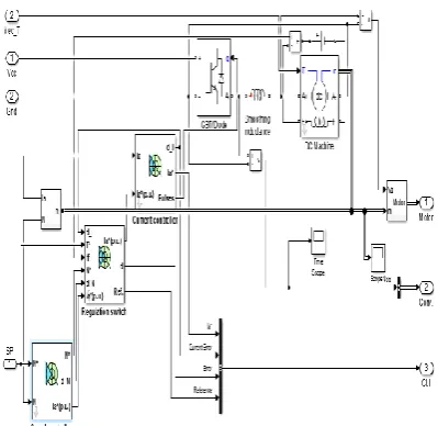
A one-quadrant Direct Current (DC) drive to hysteresis current control with speed regulation was designed to help simulate the equipment. The circuit is based on Simscape Power Systems™ of the DC5. It was model on a one-quadrant chopper buck converter drive of a DC motor. The DC motor of HP supplies with a constant approximately 150V DC. The voltage in the armature is supplied by an IGBT buck converter controlled by two regulators. A 220 V DC voltage source feeds the converter. The first regulator is a PI speed regulator, followed by a hysteresis current regulator. The speed regulator armature controller to obtain an output of the electromagnetic torque needed to reach the desired speed. To avoid sudden changes that could cause overloading of current on the armature and destabilize the system. The armature current is controlled by the current regulator by delivering the correct pulses to the IGBT device to maintain the flow in the armature within the hysteresis loop. The frequency of the IGBT device is limited by the motor inductance and an external inductance placed in series with the armature circuit.
2) HYSRERESIS MEASUREMENT
The hysteresis loop for the hysteresis-meter is plotted by drawing the magnitude of the magnetic field strength H against the importance of the magnetic induction B of the material. The flow of current through the coil causes a magneto-motive force F to generate along the path. Which dependent mostly on the distance travelled by the magnetic field lines. Therefore, the magnetic circuit length like the system results in a substantial magnitude of magnetic field strength H of A/m as the unit, which can be described by equation 1.
(1) This magnetic field magnetizes the material. This principle of magnetization is called magnetic induction or a magnetic flux density B. This degree of magnetization was measured directly by a hall magnetic sensor. However, bring a sensor to sense a magnetic property’s material require to put the sensor in the magnetic path and open the core. Therefore, this will cause a definite change of the susceptibility which makes measurement difficult [20,21]. The algorithm flow of the control system for Hysteresis-meter is shown in Fig. 2a
Figure 2a: Algorithm flow of the control system for Hysteresis-meter
3) Development Hysteresimetro
To visualize the design structure, the initial design can be seen in Figure 2b, showing the coil with sensors installed on the motor and belt, along with the sample port. To facilitate machining on the lathe, the cylinder spindle holder is used to rotate the bobbin. The motor is placed in steps and strap gears, therefore, when moving the step motor, the belt will move the sample from the door to the center of the coil. That we will have the strength of the field with different pressure. Using the capabilities of the ADC, we convert this voltage into numbers. This figure shows the field strength and is displayed on the LCD. The Arduino has six ADC channels. All can be used as inputs for analog voltage.
Figure 2b: DC Drive of Hysteresis Current Control Hysteresis-meter.
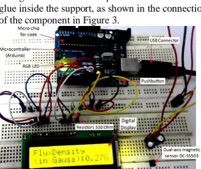
voltage flow the sensor is placed and attached with glue inside the support, as shown in the connection of the component in Figure 3.
Figure 3: Experimental setup of Magnetic Field Measurement with an Arduino micro-controller. Once positioned sensors, was rolled coil in the recessed area of TECHNYL support. The support was turned to have the recess that allowed these sensors to have a coil wound with lower difficulty and quality increase in the result — on the plate where the connectors of the sensors were fixed, mounted to a type button "Push-bottom". To start the stepper motor travel positioning the sample and beginning sensor readings when specimens were appropriately placed in the center sensor for connecting each of the sensors. These wires were attached to a plug-in the pin, so the welding time has been reduced considerably. Connectors were mounted in place in a heat shrink cover each of the sensor terminals, these being isolated from each other. With the position sensors used to allocate the lines field produced by the inductor fall perpendicularly to the sensor element. This one positioning makes the acquisition of the magnetic field measurements more reliable. This program waited until the button was pressed. While the engine was not the positioning step, the outputs of the sensors would be read. When you reach the centre position, was initiated acquisition data and data were made available to the serial port of the Arduino and so collected from an application that linked data from the serial port to a data file in Excel format). When the button was pressed again, the motor would return the sample to the starting position. The Hall Effect sensors were connected to analogue ports 0 to 4 on platform Arduino. The button was connected to the digital port 1, and the stepper motor drive was timed resulting from several calibration measurements. The equipment was assembled, and several tests were carried out with samples of varied commercial ferries. Four samples were chosen ferromagnetic materials in the form of ferrites used in making the core inductors and transformers. The content is magnesium ferrite (MnZn presents a high permeability and low resistivity) is used as a core for frequencies up to 50 MHz and has MGZN low permeability having high resistivity can be used in
rates the hundreds of MHz. We use the ground samples by mechanical process maceration.
The magnetic flux density was measured without tampering the magnetic circuit of the system. The electron magnetic force (EMF) in the windings is directly proportional to the change in flux d within the core, as shown in Equation 2.
(2) Since the product of the magnetic induction and the cross sectional area is equal to flux the density of the core = B·Ac, Therefore, the relationship between
the EMF and change of induction is expressly as equation 3 and a further integration due to change in induction dB as a function of time B result into equation 4
(3)
(4) With the use of Arduino, you can control many different directions and the speed of the motor step by step. You need an additional ULN2003 circuit controller from Arduino, which provides the correct drive to adjust the motor winding. ULN2003 is a series of high voltage and high current Darlington transistors. There are seven pairs of Darlington collectors with standard items. Each channel supports a maximum current of approximately 500 mA and 600 mA. This component is beneficial and is aimed at a wide range of DC motor solenoids, LED display, print head and high-power buffer. The same Atmega 328 microcontroller was used in the selected Arduino UNO platform sensor to read the Hall effect values. The interface of the Arduino card facilitates the detection of the device when reading the values in the USB port of the monitor on the monitor. In this way, both the position of the sample and the measured magnitude of the test take place automatically.
III. RESULTS AND DISCUSSIONS
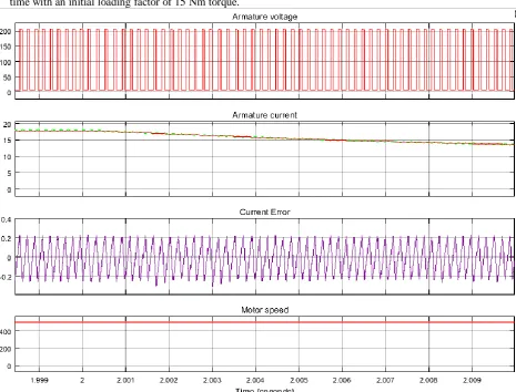
will have access to the practical situations before discussing it theoretically. When simulating the motor armature voltage and current, there was a signal in the IGBT pulses and the motor speed of the device. The current and speed references with the reference voltage and current error of the system are also displayed, as shown in Fig 4A. The speed reference is set at 500 rpm at 0second of time with an initial loading factor of 15 Nm torque.
The motor speed follows the reference ramp accurately 252 rpm/s and reaches steady-state of about 2.5seconds. The armature current follows the current reference accurately and stays within the limit hysteresis band which is explained by Fig. 4B. The recovery of the motor speed was fast and is back at 500rpm of 3second.
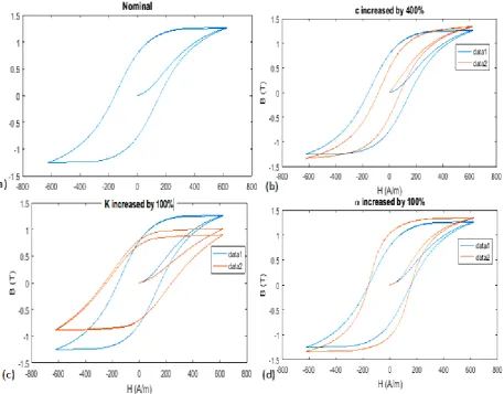
Figure 4B: Hysteresis loop for a ferromagnetic material (a) BH-loops of Nominal (b), BH-loops with C increase by 400% passive with the saturation point (c) BH-loops with K increase of 100% and the saturated
point (d) BH-loops with by 100% and the saturated point
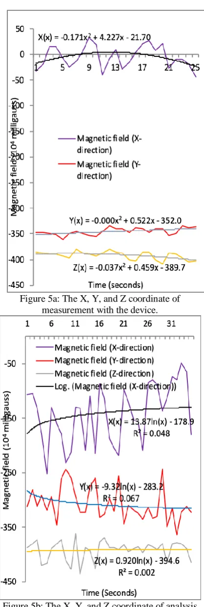
The was increased in the current to approximately 16.7A to generate a higher electromagnetic torque to maintain the reference speed. At 3seconds of the operational time, the speed reference decreases to 350 rpm which makes the armature current to drop for the momentum to decline following the negative rate, the slope of -250 rpm/s as shown in Fig. 5a when loading the torque and the system stabilises at a particular time, approximately 4secons around the reference point, as shown in Fig. 5b The properties of raw material were measured using the developed device. It was ensured that the value on the display screen of the PC was stable before taking the readings serially. The amount of the magnetic text of the x, y, and z-direction are shown in Fig.
Figure 5a: The X, Y, and Z coordinate of measurement with the device.
Figure 5b: The X, Y, and Z coordinate of analysis with simulation software.
We then move the magnet to match the area next to the sensor and write the reading value for each position associated with the sensor. For each value, we will remove the corresponding values when the magnet is away from the device to remove the
Earth's magnetic field. Benefits will be shown after receiving all benefits. To determine the SX and SY matrix from the values measured with the measured values for X and Y respectively, it is logged in the MATLAB software, which makes the spatial distribution of the measurements reliable. This is repeated, and the values are shown in Figures 5a and 5b showing the histogram curve of the TH50 and the loop element in the first quadrant. Measurements taken from the sample after heat treatment to reduce stress can be seen in Figure 6. Observed values for magnetic fields.
Figure 6: Experimental Hysteresis curve for Sample in the first quadrant.
IV. CONCLUSIONS
This research presents the results of the data acquired from the measurement of the magnetic field using Arduino and simulations of the average values of the material. The result obtained shows the possibility and verification of the consistency of the device, which showed satisfactory results and its applicability in Institutions and industries. The following conclusion can be reached.
[1]. Arduino UNO was incorporated into the system with a series of embedded magnetic sensors along the magnetic field. It established the types of materials for their magnetic classification and solved the problem of measuring areas, and sorting articles according to their behavior when subjected to electromagnetic fields.
ability to indicate the average hysteresis properties of inhomogeneous materials.
[3]. The treatment of data acquired was due to typical values and building graphics. Fundamental values were mathematically obtained and compared to the benefits received experientially by analyzing the charts, which were possible to verify linearity equipment, which showed satisfactory results. [4]. The necessary parameters of electric, magnetic and electromagnetic field were proposed and established for Histeresimetro. The optimization of a density magnetic field to enhance the sensitivity of the device was introduced and measures the degree of hysteresis materials with a reduced cost that favor an economic effect.
[5]. The interface between the sensors and the user is made through an Arduino UNO. The cost of energy and heat generation during magnetic field measurement was minimized.
REFERENCES
[1] Jolanta Zwolińska, The use of magnetic fields in the treat. of patients with rheumatoid arthritis. Review of the literature. Reumatologia. 2016; 54(4): 201–206. doi: 10.5114/reum.2016.62475.
[2] Xue Z, Li L, Ichchou MN, Li C. Hysteresis and the nonlinear equivalentpiezoelectric coefficient of MFCs for actuation, Chin J Aero (2016). http://dx.doi.org/10.1016/j.cja.2016.07.002.
[3] Lelièvre D, Colinart T, Glouannec P. Hygrothermal behaviour of bio-based building materials including hysteresis effects: Experimental and numerical analyses. Energy Build 2014; 84:617-27.
[4] Dylan L, Thibaut C, Patrick G. Modeling the moisture buffering behaviour of a coated biobased building material by including hysteresis, Energy Procedia 2015;78:255 – 260.
[5] Oladapo BI, Balogun VA, Adeoye AOM, Ijagbemi CO, Afolabi SO, Daniyan IA, et al. Model design and simulation of automatic sorting machines using proximity sensor, Eng. Sci. Technol. Int. J. 2(2016)2.
[6] Kranz B, Benjeddou A, Drossel WG. Numerical and experimental characterizations of longitudinally polarized piezoelectric d15 shear macro-fiber composites. Acta Mech 2013;224(11):2471–87.
[7] Hu Z, Smith RC, Burch N, Hays M, Oates WS. A modelling and uncertainty quantification framework for a flexible structure with macrofiber composite actuators operating in hysteretic regimes. J Intell Mater Syst Struct 2014;25(2):204–28.
[8] Kranz B, Benjeddou A, Drossel WG. Numerical and experimental characterizations of longitudinally polarized piezoelectric d15 shear macro-fiber composites. Acta Mech 2013;224(11):2471–87.
[9] Oladapo BI, Balogun VA, Oyegoke S, Adeoye AOM, Ijagbemi CO, Afolabi SO, et al. Experimental analytical design of CNC machine tool SCFC based on electro-pneumatic system simulation, Engg Sci and Tech, an Inter J 2016;19:1958–1965.
[10] Chao L, Yi Z, Longqing Q, Hui D, Hans JK, Xiaoming X, et al. Permanent magnet pre-polarization in low field MRI measurements using SQUID. Physics Procedia 2012;36:274 – 279.
[11] Jianli J, Hanbing L, Shuang Z, Bo J, Guanghe L, Odafe E, et al. Magnet bioreporter device for ecological toxicity assessment on heavy metal contamination of coal cinder sites, Sensors and Actuators B: Chemical 2016;222:290– 299.
[12] Hongyue J, Peter A, Timothy M, Yuehwern Y, John WS. Comp. Life Cycle Ass. of NdFeB Magnets: Virgin Prod. versus Mag. Mag. Recycling. Procedia CIRP 48 2016; 48:45 – 50.
[13] Raj JR, Rahman SMK, Anand S. Microcontroller USB interfacing with MATLAB GUI for low-cost medical ultrasound scanners. Engg Sci and Tech, an Inter J 2016;19:964–969.
[14] Ijagbemi CO, Oladapo BI, Campbell HM, Ijagbemi CO. Design and simulation of fatigue analysis for a vehicle suspension system (VSS) and its effect on global warming. Procedia Engg 2016; 159:124 – 132.
[15] Bochkarev IV, Khramshin, RR. Device for monitoring permanent magnet friction brakes. Procedia Engg 2016; 150:26 – 31.
[16] Yuhi Y, Toshiro K. Voltage controlled duplexer-integrated leaky-wave antenna using magnet-less Non-reciprocal Metamaterial (MNM), J. Electr. Syst. Inform. Technol, (2016). http://dx.doi.org/10.1016/j.jesit.2016.10.015. [17] Oladapo B I, Balogun V. A, Afolabi S O, Azeez M T,
Asanta A S. Simulation model to explore the characteristic pump curve of an injection molding machine: a case study of ABUAD water plant, Int. J. Eng. Bus. Enterprise Appl 2015;13(1):63–68.
[18] Freetronics. Hall Effect Magnetic and Proximity Sensor Module. 2010-2015. Available: http://www.freetronics.com.au/products/hall-effect-magnetic-and-proximity-sensor-module#.V3wujfkrLIU. [Accessed 06 July 2016].
[19] Sounds DL, Kodera T, Caloz C. Electromagnetic modeling of a magnetless nonreciprocal gyrotropic metasurface. IEEE Trans 2013;61:(1)221–231.
[20] Dmitry K, Volker P. Busbar arcs at large fusion magnets: Model experiments on busbar arcing in a double-walled feeder tube with the LONGARC device, Fusion Engg and Des 2016;109-111(1):1217–1221.
[21] Measuring the magnetic hysteresis, Last Modification:
September 20, 2013.