TEST PLATFORM, DATA COLLECTION, SYSTEM IDENTIFICATION OF
MULTICOPTER VEHICLE
MSc. Taner Mutlu, Prof.Dr. Cengiz Hacızade
ISTANBUL TECHNICAL UNIVERSITY, FACULTY OF AERONAUTICS AND ASTRONAUTICS, ISTANBUL, TURKEY
E-mail: [email protected] , [email protected]
Abstract: Multicopters are widely used in a professional manner today in film industry, military applications etc. These vehicles are easy to build which have mechanical and electrical parts. Also autopilots are being sold to control these vehicles. However, mostly these vehicles are being built and used with little knowladge about the system dynamics, performance and stability. Mostly wrong propeller motor battery combinations are used. And mostly these vehicles are being used by different payloads. Every change in payload changes dynamics and stability of the vehicle. Very little of users are eligible at PID tuning and increasing the stability of multirotor vehicles. We aim to provide a test platform and methodoly for system identification and increasing stability of Multirotor Vehicles.
KEYWORDS: MULTIROTOR, SYSTEM IDENTIFICATION, KALMAN FILTER, TEST PLATFORM, MATHEMATICAL MODEL
1. Introduction
In this study real time data collection and system identification of dynamic parameters of a multicopter type robotic vehicle is aimed. A test bed for safe testing of the vehicle and isolation of required degrees of freedom is built. Sensors are mounted and data is transferred to computer real time. The PC is used for develeopment of sensor fusion algorithms, real time parameter estimation and adaptive control algorithm development and visualisation. On computer MATLAB Real Time Windows Target is used. The ultimate aim is to precisely model the multicopter vehicle, and build a robust controller. Sub Parts will be modeled as well as the whole vehicle. Stability nalysis of single DOFs and cross coupling will be investigated. Kalman Filter for sensor fusion will be applied[1,5].
2. Design Considerations
Frame: there are many frame types available for multicopter design. The most important parameter of frame is its rigidity which should not let unwanted vibrations to be transferred from motor-props to the sensors. Tricopter: this frame type is formed by three arms and three prop-motors and a servo motor to control the tail motor roll angle. Since it is not symmetrical torque balance is obtained by tail servo. They suffer from less than stellar perfomance and are not suitable for larger sizes. Quadcopter: this frame is most common, it is symmetrical and embody the simplest priniple of operationfor controlling roll, pitch and yaw operation. There are many variations of Quadcopter frames, +, X, Dead Cat, H The X frame is considered best for flight performance and stability since its natural symmetry balances flying forces better. Long endurance multicopters are generally chosen X frame with low RPM high wattage and big size props. İt is possible to obtain 60min flight times. Hexacopter and Octocopter are chosen for professional heavy lift tasks such as professional heavylift cameras. In filming camera vibration is very important and should be omitted. With heavy lifts hexa and octo frames provide more stable less vibration flights. But at a cost of efficiency compared to quadcopters. Also they are more prone to failure since they have more components. It is a possibility with these frames to safely land even with one motor failure. Y6 and X8 frames are double contra rotating prop designs which provide most lift in smaller area, but again at a cost of efficiency. Which is about 20-30%
compared to regular frames. On the contrary, on heavy duty airplanes contra-rotating props have 7% more efficiency. The reason of different results is to be investigated. Maybe it is due to turbulance of downwash of upper propller in multicopters since they turn slower compared to on airplanes. Its advantage is practical frequent usage due to its smaller size.
Power train(Motor-Prop-Battery): The flight time, take-off weight capacity, dynamic behaviour is mostly related to power train. The multicopter design should fit to the task. For long endurance multicopter lesser arm frame with low RPM high power motors matched with big size propellers and suitable voltage-weight battery should be chosen. Also the propeller pitch angle is chosen smaller. The higher the motor RPM needs to be the lesser is the efficiency. The long endurance designs are less stable with heavier payloads due to big prop sizes. For heavy duty applications a little bit higher RPM high power-to-weight motors are chosen. Not too high as airplane, since they use smaller high pitch propellers with high RPM motors. Frame is generally chosen Hexa or Octo for stability and chance of survival on one motor failure. If power to weight ratio high enugh, autopliot will be able to safely control the multicopter, and save the expensive heavy payload.
Picture 1: X type frame quadcopter picture
3. Tests and Data Collection
Test apparatus data collection and system identification has been designed. One test bed is single axis Degree of Freedom ball bearing table for one axis, two axis and three axis dynamic behaviour investigation of multicopter. In this test bed yaw, torque, pilot stick input to roll, ad pilot stick input to pitch respose can be invesitgated and safely recorded for system identification.
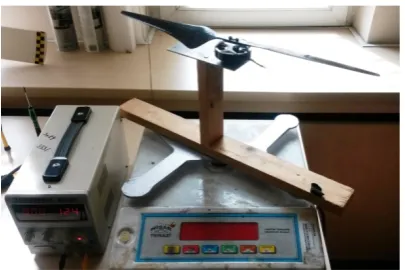
Second test bed is power-train test bed where the the whole components of the power train(Propeller-Motor-Motor Driver-Battery-Pilot input) can be tested at once. This test bed is good for finding the most efficient propller-motor-battery combination, testing the motor driver performance, and collecting data for power-train transfer function system identification mathematical model.
Picture 2: Power train test platform
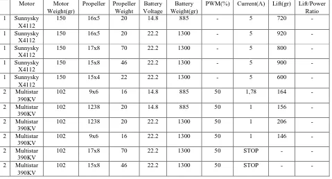
Power train system is tested using a variable power supply, precision scale, motor, propeller and motor driver with variable PWM input. Lift, Voltage, PWM Percentage, RPM, Current Drawn is measured. Also the effect of imbalance of propellers and motors due to RPM can be measured by adding an accelerometer to the test bench. Power train vibration reduction is problem which should be absolutely minimized. In table 1 the power train system measurements can be seen, most the measurements are omittied because of scarce space. 5 different motor, 10 different propellers, two voltage values are simultaneously measured.
Picture 3: 3DOF Test platform for quadcopter, multicopter and
helicopter around ball bearing fixture
4. Sensors and Modelling
Magnetic Sensor Model: The MEMs sensor HMC5883 is used for measurement of Magnetic Heading
IMU Model: The MEMs IMU is MPU6050 , in Simulink IMU model natural frequency, noise, bias, and damping parameters can be simulated.
Power-Train Model: Power train model is considered as combination of Battery-Motor Driver-Motor-Propeller. The input is a Pulse Width Modulation (PWM) signal from autopilot which is 1-2ms interval 50Hz signal(some autopilots may have shorter control loops.)
Earth magnetic model: The earth magnetic deviations are modelled using simulink. The mathematical model accepts date and GPS coordinates and gives the magnetic heading deviation. Earth magnetic model is constructed using USGS measurement database[3].
Figure 1 : Earth Magnetic Deviation Model.
Earth magnetic model shows us that the magnetic deviation is +-20degrees.
GPS model error is +-10m. GPS error is simulated using Zero-Order Gauss Noise.
The generalized coordinates for a rotorcraft are: Q=(x,y,z,θ,φ,ψ)
After calculations following are the non-linear equations of motion[1]:
𝑚𝑚𝑥𝑥̈ = −usinθ
𝑚𝑚𝑦𝑦̈ = ucosθsinφ
𝑚𝑚𝑧𝑧̈ = ucosθcosφ − mg
φ̈ = τ�φ
θ̈ = τ�θ
𝜓𝜓̈ = τ�𝜓𝜓
The first control input is u which is defined as follows:
𝑢𝑢=𝑓𝑓1+𝑓𝑓2+𝑓𝑓3+𝑓𝑓4
𝑓𝑓𝑖𝑖=𝑘𝑘𝜔𝜔2
The desired outputs for each individual motor can be calculated from the following equation:
� 𝑢𝑢 τ�θ
τ�φ
τ�𝜓𝜓
� = � 1 −𝑐𝑐
0 −𝑙𝑙
1 𝑐𝑐 −𝑙𝑙
0
1 −𝑐𝑐
0 𝑙𝑙
1 𝑐𝑐 𝑙𝑙 0
� � 𝐹𝐹1
𝐹𝐹2
𝐹𝐹3
𝐹𝐹4
�
where c is the torque produced by each motor about the ψ axis
and l is the moment arm to each motor[4].
5. System Identification
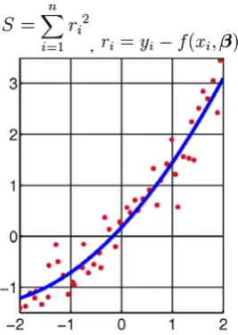
System identificaiton is the process of measuring the inputs and outputs of a dynamical system and obtaining the mathematical model of system. For this purpose precise measurement and correct test system setup is very important. The control inputs scenarios should be carefully selected selected so as much as bandwith of the system is considered. Inputs can
,
Figure 2 : Curve fitting with quadratic function
6. Precautions and means for resolving the problem
Testing the device on air is a time consuming and costly procedure. For overcoming this problem a 3DOF test platform is built. Any axis can be limited to individually test the vehicle while collecting data real time.
7. Simulation
Sensors are modelled and simulated using MATLAB Simulink software. In simulation Earth magnetic model, IMU, GPS are modelled and simulated. Also Senseo integration with Kalman Filter is realized. The GPS error is reduces from 10m to 1m.
8. Conclusion
The dynamics and behaviour of a multirotor vehicle is investigated using a test platform both for complete vehicle and single actuator part only. When modelling not only the vehicle but sub components are also being modeled. Motor-Prop-Battery power train is modeled. Single axis control and output is modelled. Sensor behavious is investigated and modeled.
There are many papers focused on multirotors investigating different aspects. Many investigate mathematical model generally, however the sub parts and vibration effects of sub parts locally and overall are not well investigated. Many research papers invesitgate a preconfigured multicopter, however here we state that multicopter should be precisely designed according to payload and flight performance parameters required.
9. Literature
[1] http://diydrones.com/
[1] Michael A. Demetriou , Design Optimization of a Quad-Rotor Capable of Autonomous Flight, WORCESTER POLYTECHNIC INSTITUTE
[3] Taner Mutlu, Chinghiz Hajiyev, Modelling And Integration Of Navigation Sensors, Xsemetro, Bueonos Aires, 2013 [4] http://geomag.usgs.gov/
[5] R. M. Rogers, “Applied Mathematics in Integrated Nnavigation Systems,” American Institute of Aeronautics and Astronautics, 2000.
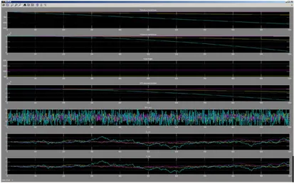
Figure 3 : Sensor Simulation of GPS, Magnetometer, Earth Magnetic Model and IMU
Figure 4 : GPS simulation results(+-10m)
Figure 5: Inertial Axis velocity, position, GPS measurements, GPS real errors, and Kalman Filter estimation outputs are shown. Six Degree of Freedom Motion Platform
Copyright 1990-2010 The MathWorks, Inc.
Yaw moment
h (m)
µ (deg)
l (deg)
Decimal Year Magnetic Field (nT)
Horizontal Intensity (nT)
Declination (deg)
Inclination (deg)
Total Intensity (nT)
World Magnetic Model 2010
Uniform Random Number2 Uniform Random
Number1 Uniform Random
Number ECEFheight
To Workspace7
w_true
To Workspace6
A_true
To Workspace5
w_measured
To Workspace4 A_masured
To Workspace3
GPS_pos_Xe_Ye_Ze
To Workspace2 ECEFposition
To Workspace1 velocity
To Workspace
A
b (m/s 2) ω (rad/s) dω/dt CG (m)
g (m/s2) Ameas (m/s2) ω
meas (rad/s)
Three-axis Inertial Measurement Unit Roll moment
Pitch moment
0
Mzz Slider 0
Myy Slider 0
Mxx Slider
1.Xe
1.φθψ
MATLAB Animation
Kalman Filter Z Z Z
Z_est
X_est Z_est Z_est Z_est Z_est
Kalman Filter Inertial1
Inertial 0.25
Fz Slider 0.5
Fy Slider 1
Fx Slider
Xf
µ l
h
ECEF Position to LLA
2010
Constant5
[0 0 -9.81]
Constant1
(0 0 0)
Constant 1
1 1
0
Clock
Body rad deg
rad deg
Add Fxyz (N)
M
xyz (N-m)
Ve (m/s) Xe (m) φθψ (rad)
DCM
be
Vb (m/s) ω (rad/s)
dω/dt
Ab (m/s2) Body Euler Angles
Fixed Mass
6DoF (Euler Angles)
Velocity in Body Axes Velocity in Inertial Axes
Velocity in Inertial Axes
Position in Inertial Axes Position in Inertial Axes
Euler Angles Euler Angles
Body Rotational Rates
X konum
Y konum
Figure 6 : GPS static position simulation
Figure 7 : Earth magnetic model simulation
Figure 8 : IMU 6DOF simulation model
Table 1: Power train measurements
Motor Motor
Weight(gr)
Propeller Propeller
Weight
Battery Voltage
Battery Weight(gr)
PWM(%) Current(A) Lift(gr) Lift/Power
Ratio
1 Sunnysky
X4112
150 16x5 20 14.8 885 - 5 720 -
1 Sunnysky
X4112
150 16x5 20 22.2 1300 - 5 920 -
1 Sunnysky
X4112
150 17x8 70 22.2 1300 - 5 800 -
1 Sunnysky
X4112
150 15x8 46 22.2 1300 - 5 900 -
1 Sunnysky
X4112
150 15x4 22 22.2 1300 - 5 600 -
2 Multistar
390KV
102 9x6 16 14.8 885 50 1,78 164 -
2 Multistar
390KV
102 1238 20 14.8 885 50 1 156 -
2 Multistar
390KV
102 1238 20 22.2 1300 50 1 206 -
2 Multistar
390KV
102 9x6 16 22.2 1300 50 1 146 -
2 Multistar
390KV
102 17x8 70 22.2 1300 50 STOP - -
2 Multistar
390KV
102 15x8 46 22.2 1300 50 STOP - -
h (m)
µ (deg)
l (deg)
Decimal Year
Magnetic Field (nT)
Horizontal Intensity (nT)
Declination (deg)
Inclination (deg)
Total Intensity (nT) World Magnetic Model 2010
Display4 Display3 Display2 Display1 Display
2010
Constant3 41
Constant2 39
Constant1 100
Constant
Gyro
To Workspace1 IMU
To Workspace Ab (m/s2)
ω (rad/s) dω/dt CG (m)
g (m/s2)
Ameas (m/s2)
ω
meas (rad/s)
Three-axis Inertial Measurement Unit [0 0 -9.81]
Constant1 (0 0 0)