© 2017 IJSRST | Volume 3 | Issue 7 | Print ISSN: 2395-6011 | Online ISSN: 2395-602X Themed Section: Science and Technology
Mitigation of Harmonic Current Using Active Filter with Fuzzy Control in
Distribution System
N. Gurumohan Reddy1, Dr. K. Jithendra Gowd2
1PG scholar, Department of Electrical and Electronics Engineering, JNTUA Anantapur, India 2Assistant Professor, Department of Electrical and Electronics Engineering, JNTUA Anantapur, India
ABSTRACT
Maintaining voltages within tolerable limits is of prime importance in distribution system . Voltage distortion due to harmonics is main concern which affects the distribution voltages to fall out of limits. A shunt connected active filter with Fuzzy logic controller is able to suppress harmonic resonance within the distribution facility. However, inherent phase-lagging in digital signal processing of active filter affects its functioning which might induce unintentional harmonic amplification at alternative locations within the feeder . This paper presents an active filter with fuzzy control to suppress harmonic resonance.. The current control is realized by parallel-connected band pass filters tuned at harmonic frequencies to ensure that the active filter functions as an approximately pure conductance. The electrical phenomenon at dominant harmonic frequencies is individually and dynamically adjusted to ensure the damping performance. Additionally, so as to handle the harmonic resonance, the load distributed-parameter model of a radial feeder is developed with considering harmonic damping by variable electrical phenomenon and admittance, separately. Simulation results show that the active filter with fuzzy control will effectively reduce voltage harmonic distortions. Simulation was done by using MATLAB/Simulink software.
Keywords: Active Filter, Harmonic Resonance, Voltage Distortion, Fuzzy Control.
I.
INTRODUCTION
Equipment operates satisfactorily for the rating they have designed and they withstand some margin of tolerable limits. Voltage distortion, due to harmonic resonance can affects the performance of distribution equipment in ways such as heating, vibration etc. thus it has received serious concerns in the distribution power system [2], [3], [4], [5], [6]. This scenario becomes significant due to extensive use of nonlinear loads as well as high penetration of inverter-based distributed generation systems. Maximum allowable voltage total harmonic distortion (THD) is 5% and individual voltage distortion is 3% in distribution networks below 69kV. This guideline is also included in IEEE standard for interconnecting distributed resources with electric power systems (IEEE std. 1547.2- 2008). Tuned-passive filters are typically adopted to cope with harmonic issues, but their functionality may suffer from component aging, frequency shifting, or unintentional resonances. They
require time to time calibration to maintain their filtering performances.
droop-control [13], on-line optimization [14], [15], particle swarm optimization [16] or single-frequency tuned algorithm [17]. In a nutshell, the active filter working as harmonic conductance is able to suppress the propagation of harmonic voltage on the feeder. However, instead of conductance, the active filter presents inductive characteristic at harmonic frequencies due to the limited bandwidth of the current control [18]. The phase lagging may be further worsening by the controlling delay of the active filter in the digital system. Thus the harmonic admittance deteriorates the damping performance of the active filter, or even result in the “whack-a-mole” issue.
Various current control methods have been proposed for active power filters. Hysteresis current regulator is simplest, but low-order harmonics resulting from variable switching frequency may become a serious concern [19]. Repetitive control with selectively harmonic compensation is very popular. However, this approach may suffer from heavy computing loading [20]. A shunt active filter with asymmetrical predictive current control was presented for harmonic-resonance suppression in the power system [21], [18], and [22]. In this application, current-tracking capability is very sensitive to parameter variations. Analysis of stability margin of the active filter was discussed in [18]. Recently, resonant controls have been applied for the active power filters. Most of research was simply focused on harmonic current compensating at load side [23], [24], [25], [26], [27], [28].
In the previous work, the author has presented the resonant current control for the shunt active power filter to dampen harmonic voltage propagation [29]. The resonant current regulators composed of various parallel-connected band-pass filters tuned at harmonic frequencies to control the active filter as an approximately pure conductance [30], [31]. The conductance of each harmonic frequency is designed to be separately and dynamically adjusted to guarantee the damping performance. In this study, the impact of phase lagging on harmonic damping performance is further investigated by using the line distribution-parameter model. Damping performance of the active filter is also analyzed when different current controls are implemented and when nonlinear loads are deployed at different locations. Experimental results from a
prototype circuit based on 220V/10kVA system verify theoretical analysis.
II.
OPERATION PRINCIPLE
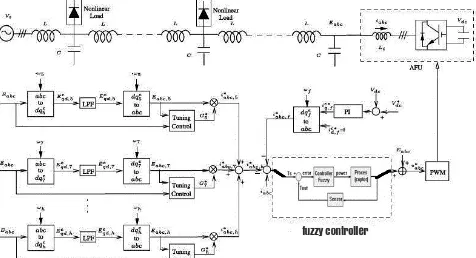
The distribution network is considered as a simplified one-line circuit diagram with active filter and the associated control are shown in Fig.1. The active filter unit (AFU) is installed at the end of a radial line to suppress harmonic resonance. The AFU susceptance is made zero to operate it as a variable conductance for different harmonic frequency as given,
∑ 1
Where h represents the order of the harmonic frequency. The conductance command G*
h is defined as a control
gain to dampen harmonic voltage Eabc,h. As shown in Fig.
1, the control is composed of harmonic-voltage extraction and tuning control, followed by the current regulation and PWM algorithm. Operation principle and design consideration are given as follows.
A. AFU design and control
Synchronous reference frame (SRF) transformation is used to find Harmonic voltage at the different harmonic frequencies. The specific harmonic voltage component becomes a dc value after Eabc is transformed into the
SRF at ωh. The dc value and then the corresponding
harmonic component Eabc, h is obtained when applied to a
low-pass filter (LPF). It is worth noting here that a phase-locked loop (PLL) is required to determine system frequency for implementation of SRF. ωh should be set
as a negative value for negative-sequence component (i.e., fifth) or a positive value for positive-sequence harmonic component (i.e., seventh), respectively. Fig. 2 shows the tuning control for the conductance command
G*h. As illustrated, G*h is determined according to the
harmonic voltage distortion VDh at the AFU installation
point Eabc, in which VDh is defined as the percentage
ratio of the harmonic voltage component Eh (rms value)
to the voltage E (rms value) by
2
√∫
3
√∫
The derivation of VDh is approximately evaluated by
using two LPFs with cut-off frequency at ωc, which are
to filter out ripple components in the calculation. . The error between the allowable harmonic voltage distortion VDh and the actual harmonic voltage distortion VDh is
then fed to a PI regulator to adjust the conductance command Gh
Fig. 1.Block diagram of Active filter with fuzzy control.
Fig. 2. Tuning control of the conductance command
Fig. 3. Current control block diagram of the proposed AFU.
Fig. 4. Voltage control block diagram of the proposed AFU in the distributed power system.
The total current command is the summation of fundamental current command i*abc,f and all harmonic
current commands i*abc, h which is equal to the product
of the harmonic voltage and its corresponding conductance command. i*abc, f shown in Fig.1 is the
in-phase fundamental current command generated by a PI control to control the dc voltage Vdc of the AFU. In
order for the active filter to guarantee current tracking capability, the resonant current regulator is realized by:
∑
where kp is a proportional gain and ki , h is an integral
gain for individual harmonic frequency, respectively. The current control is tuned to resonate at harmonic frequencies ωh, so that various narrow gain peaks
centered at harmonic frequencies are introduced. The damping ratio ξ is designed to determine the selectivity and bandwidth of the current control. Accordingly, the voltage command Vabc is obtained for PWM to
synthesize the output voltage of the active filter.
B. Modeling of Control
Nomenclature used in this section is given as:
Vsh (s): harmonic voltage at the source terminal
Eh(s): harmonic voltage at the installation
location of the active filter
Ih (s) : harmonic current of the active filter
Ih (s) : harmonic current command of the active
filter
Line voltage 11.4 kV Line frequency 60 Hz Feeder length 9 km
Line inductance 1.55 mH /km (4.5 %)
Line resistance 0.36 Ω /km (1.2 %) Line capacitance 22.7 µF / KM
(11.1 %) Characteristic impedance, Z0 8.45 Ω
Wavelength of 5th harmonic,
λ5
17.8 km
Wavelength of 7th harmonic,
λ7
12.7 km
Table 1: parameters of given power line
capability can be simply evaluated by using bode plots of open-loop and closed-loop transfer functions. Fig.4 shows the block diagram for harmonic damping analysis. The distribution network is replaced with a second order resonant tank (Ls, Cs, Rs) as indicated by the dashed box.
Here, the resonant tank is tuned to amplify the harmonic voltage Eh(s). Note that the scheme of harmonic
detection at ωh is equivalent to a single-side band pass
filter in the stationary frame. The transfer function H(s) can be expressed as shown in fig.(4), where ωh is the
harmonic frequency and TLPF is time constant of the
low-pass filter, which is used to filter out the dc component in the rotational reference frames. Thus the damping performance of the AFU can be evaluated by the harmonic-voltage magnification
shown in Fig.
4.
( ) 5
III.
HARMONIC RESONANCE
Parameters of a sample feeder are given in TABLE I. In this section, harmonic resonance along the feeder was found by evaluating the line distributed-parameter model. Harmonic voltage can amplified if harmonic standing wave is generated [10]. The active filter is assumed to be installed at the end of the line (x = 9). Considering both feeder and damping impedance provided by the filter.
Voltage base 220 V Current base 52.5 A Impedance base 2.42 Ω Conductance base 0.413 Ω-1
Table 3: Base values
IV.
FUZZY INFERENCE SYSTEM
Fuzzy logic block is prepared using FIS file in MATLAB 7.8.0.347(R2009a) and the basic structure of this FIS editor file as shown in Fig. 5. This is implemented using following FIS (Fuzzy Inference System) properties:
Fig.5. Fuzzy Inference System
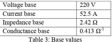
In FLC, basic control action is determined by a set of linguistic rules. These rules are determined by the system. Since the numerical variables are converted into linguistic variables. The FLC comprises of three parts: fuzzification, interference engine and defuzzification. The FC is characterized as i. seven fuzzy sets for each input and output. ii. Triangular membership functions for simplicity. iii. Fuzzification using continuous universe of discourse. iv. Implication using Mamdani‟s, „min‟ operator. v. Defuzzification using the height method.
Fig.6. Fuzzy logic controller
A. Fuzzification: Membership function values are assigned to the linguistic variables, using seven fuzzy subsets: NB (Negative Big), NM (Negative Medium), NS (Negative Small), ZE (Zero), PS (Positive Small), PM (Positive Medium), and PB (Positive Big). The Partition of fuzzy subsets and the shape of membership
CE (k) E (k) function adapt the shape up to appropriate
system. The value of input error and change in error are normalized by an input scaling factor.
Change in error
Error
NS PB PM PS PS Z NM NB Z PB PM PS Z NS NM NB PS PM PS Z NS NM NB NB PM PS Z NS NM NM NB NB PB Z NS NM NM NB NB NB
Table 2: Fuzzy Rules
In this system the input scaling factor has been designed such that input values are between -1 and +1. The triangular shape of the membership function of this arrangement presumes that for any particular E (k) input there is only one dominant fuzzy subset. The input error for the FLC is given as
E (k) =
(6)
CE (k) = E (k) – E (k-1) (7)
C. Inference Method: Several composition methods such as Max–Min and Max-Dot have been proposed in the literature. In this paper Min method is used. The output membership function of each rule is given by the minimum operator and maximum operator. Table 1 shows rule base of the FLC.
(a)
(b)
Fig.7. (a). Membership functions for error (b). Membership functions for change in error
(c)Membership functions for output
B. Defuzzification: As a plant usually requires a non-fuzzy value of control, a defuzzification stage is needed. To compute the output of the FLC, „height‟ method is used and the FLC output modifies the control output. Further, the output of FLC controls the switch in the inverter. In UPQC, the active power, reactive power, terminal voltage of the line and capacitor voltage are required to be maintained. In order to control these parameters, they are sensed and compared with the reference values. To achieve this, the membership functions of FC are: error, change in error and output. The set of FC rules are derived from
u=-[αE + (1-α)*C] (8)
Where α is self-adjustable factor which can regulate the whole operation. E is the error of the system, C is the change in error and u is the control variable.
V.
SIMULATION STUDIES
The active filter with the fuzzy control is simulated by using the alternative transient program (ATP). Fig. 8(a) shows the considered lumped feeder that is arranged with similar per unit value to TABLE I in the previous section. All parameters are given as follows. The harmonic resonance caused by higher order harmonics (>8) is rare in the distribution system, so the resonant current control includes fifth and seventh resonant terms only [3].
• Power system: 3φ, 220 V (line-to-line), 20 kVA, 60 Hz. Base values are listed in TABLE II.
(b)
(c)
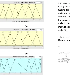
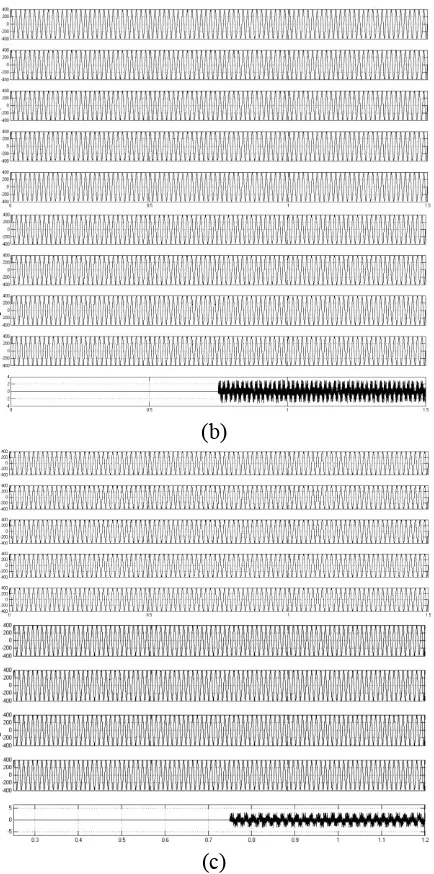
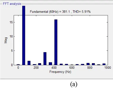
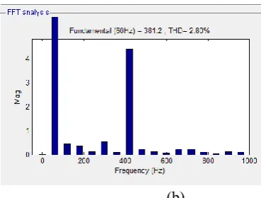
Fig. 8. (a). Simulation circuit configuration .simulation results when (b) AFU is off (c) AFU is on
Line parameters: L=3.1 %, C=13.7 %.
Nonlinear loads: NL1 and NL2 are constructed by three phase diode-bridge rectifiers, and consume real power 0.25 pu, respectively.
Linear loads: Both linear loads are initially off. LL1, LL2 are rated at 0.1 pu (pf=1.0), 0.09 pu (pf=0.9), respectively.
Tuning control: k1=100, k2=2000, ωc=62.8Rad/s, VD h=3.0%.
The AFU is implemented by a three-phase voltage source inverter with PWM frequency 10 kHz
A. Steady-state results
Fig. 8(b) shows bus voltages are severely distorted before the AFU is initiated. For example, voltage THDs at bus 3 and bus 9 are 5.6% and 6.1%, respectively. Fig.9 illustrates voltage VD5, VD7 on each bus. We can
observe cyclic amplification of voltage distortion along the line
G*5 G*7
NLs at Bus 2,5 1014 pu 1.28 pu
NLs at Bus 3,7 1.19 pu 0.32 pu
NLs at Bus 4,6 3.15 pu 1.23 pu
Table 4: AFU CONDUCTANCE COMMANDS
Fig. 9. VD5 and VD7 on all buses before and after the
AFU is in operation.
and seven harmonic resonance is dominant. This result confirms the previous analysis by harmonic distributed-parameter model. After the AFU starts in operation, Fig. 8(c) shows voltage distortion is clearly improved. Voltage THD at bus 9 is reduced from 5.91 % to 2.80%, which contains 3.0% fifth harmonics and 3.0% seventh harmonics. The blue curves of Fig. 9 demonstrate that both VD5 and VD7 become more uniform along the line.
At the steady state, the AFU is operated at G5 = 1.14 pu
(a)
(b)
(c)
Fig. 9. AFU transient behavior (NL1, NL2 are increased at t=1.5 s, t=2.0 s, respectively, and then LL1, LL2 are turned on at t=2.5 s, t=3.0 s, respectively.) (a)
Harmonic-voltage distortion when the AFU is OFF. (b) Active filter conductance commands. (c) Harmonic-voltage distortion when the AFU is ON.
A. Voltage damping analysis
Harmonic suppression capability of the AFU with fuzzy control is evaluated in this section which is evaluated based on Fig. 4 considering AFU control, including phase lagging and current control. The resonant tank (Cs=717uF, Ls=200uH, Rs=0.1) is tuned to amply
seventh harmonic voltage. Fig.8 shows that seventh harmonic voltage is reduced and controlled by harmonic conductance after the AFU is turned on.
Fig. 10. Frequency characteristics of harmonic amplification.
B. Nonlinear loads at different locations
The damping performance of the AFU is evaluated when nonlinear loads are connected to different locations. Fig. 9, Fig. 12(a), Fig. 12(b) demonstrate voltage distortion on all buses when nonlinear loads are connected at bus 2, 5, bus 3, 7, bus 4, 6, respectively. TABLE IV lists the corresponding G5 and G7, respectively. As shown, VD7
can be suppressed for all cases after the AFU is on. However, VD5 may increase in the middle segment of
the line with increasing G 5. Fig. 9 shows both VD5 and
VD7 can be well suppressed when nonlinear loads are at
bus 2, 5. When nonlinear loads are changed to bus 3, 7, Fig. 12(a) shows the damping performance is not clear due to slight distortion. In case of nonlinear loads at bus 4, 6, large fifth harmonic conductance (G5=3.15 pu) is
required to reduce fifth voltage distortion. This results in serious fifth harmonic resonance as shown in Fig. 12(b). Therefore, the termination-installation active filter may unintentionally induce fifth harmonic resonance due to the”whack-a-mole” issue if large G5 is adopted. This
problem might be resolved by using multiple active filters, for example distributed active filter systems [13].
(b)
Fig. 9. (a). total harmonic distortion (a) when PR controller is employed (b). when fuzzy controller is
employed
(a) Nonlinear loads are at bus 3 and bus 7.
(b) Nonlinear loads are at bus 4 and bus 6. Fig. 12. Harmonic damping performances when nonlinear loads are connected to different buses.
VI.
CONCLUSION
The active filter with the Fuzzy logic Control (FLC) is proposed in this paper to suppress harmonic resonances in the distribution power system. The fuzzy control is implemented by various parallel band-pass filters tuned at harmonic frequencies so that the active filter can operate as an approximately pure harmonic conductance. Harmonic distortion by this control is drastically reduced .in order to cope with load change and system variations in distribution system a separate and tuning conductance for different harmonic frequency is also realized. The contributions of this paper are summarized as follows. Due to controlling delay, the damping active filter may unintentionally induce harmonic resonance at other locations in the feeder. This phenomenon is analyzed by using harmonic distributed-parameter model.
Based on simulations the fuzzy control is able to suppress harmonic resonance effectively. We can observe drastic change in results with fuzzy control when compared to proportional resonant current control. Multiple active filters might provide more effective performance compared to the termination installation one.
VII.
REFERENCES
[1]. Tzung-Lin Lee and Shang-Hung Hu, "An Active Filter With Resonant Current Control to Suppress Harmonic Resonance in a Distribution Power System" IEEE journal of emerging and selected topics in power electronics, vol. 4, no. 1, march 2016
[2]. W. K. Chang, W. M. Grady, and M. J. Samotyj, "Meeting IEEE-519 harmonic voltage and voltage distortion constraints with an active power line conditioner," IEEE Trans. Power Del., vol. 9, no. 3, pp. 1531-1537, Jul. 1994.
[3]. E. J. Currence, J. E. Plizga, and H. N. Nelson, "Harmonic resonance at a medium-sized industrial plant," IEEE Trans. Ind. Appl., vol. 31, no. 3, pp. 682-690, May/Jun. 1995.
[4]. H. Akagi, "Control strategy and site selection of a shunt active filter for damping of harmonic propagation in power distribution system," IEEE Trans. Power Del., vol. 12, no. 2, pp. 354-363, Jan. 1997.
[5]. C.-H. Hu, C.-J. Wu, S.-S. Yen, Y.-W. Chen, B.-A. Wu, and J.-S. Hwang, "Survey of harmonic voltage and current at distribution substation in northern taiwan," IEEE Trans. Power Del., vol. 12, no. 3, pp. 354-363, July 1997.
[6]. Y. D. Lee, C. S. Chen, C. T. Hsu, and H. S. Cheng, "Harmonic analysis for distribution system with dispersed generation systems," in International Conference on Power System Technology, 2006, pp. 1-6.
[7]. V. Corasaniti, M. Barbieri, P. Arnera, and M. Valla, "Reactive and harmonics compensation in a medium voltage distribution network with active filters," in IEEE/ISIE International Symposium on Industrial Electronics, 2007, pp. 916-921.
[8]. IEEE Recommended practices and requirements for harmonic control in electrical power systems, IEEE Std. 519-1992, 1993.
[9]. H. Akagi, H. Fujita, and K. Wada, "A shunt active filter based on voltage detection for harmonic termination of a radial power distribution line," IEEE Trans. Ind. Appl., pp. 638-645, May/Jun. 1999.
[11]. P. Jintakosonwit, H. Fujita, H. Akagi, and S. Ogasawara, "Implementation and performance of cooperative control of shunt active filters for harmonic damping throughout a power distribution system," IEEE Trans. Ind. Appl., vol. 39, no. 2, pp. 556-564, Mar./Apr. 2003.
[12]. M. Saito, T. Takeshita, and N. Matsui, "Modeling and harmonic suppression for power distribution system," IEEE Trans. Ind. Electron., vol. 50, no. 6, pp. 1148-1158, Dec. 2003.
[13]. P.-T. Cheng and T.-L. Lee, "Distributed active filter systems (DAFSs): A new approach to power system harmonics," IEEE Trans. Ind. Appl., vol. 42, no. 5, pp. 1301-1309, Sept./Oct. 2006.
[14]. W. K. Chang and W. M. Grady, "Minimizing harmonic voltage distortion with multiple current-constrained active power line conditioners," IEEE Trans. Power Del., vol. 12, no. 2, pp. 837-843, Apr. 1997.
[15]. K. Kennedy, G. Lightbody, R. Yacamini, M. Murray, and J. Kennedy, "Development of a network-wide harmonic control scheme using an active filter," IEEE Trans. Power Del., vol. 22, no. 3, pp. 1847-1856, Jul. 2007.
[16]. I. Ziari and A. Jalilian, "A new approach for allocation and sizing of multiple active power-line conditioners," IEEE Trans. Power Del., vol. 25, no. 2, pp. 1026-1035, Apr. 2010
[17]. X. Sun, J. Zeng, and Z. Chen, "Site selection strategy of single frequency tuned r-apf for background harmonic voltage damping in power systems," IEEE Trans. Power Electron., vol. 28, no. 1, pp. 135- 143, Jan. 2013. [18]. P. Jintakosonwit, H. Fujita, and H. Akagi, "Control and performance of a full-digital-controlled shunt active filter for installation on a power distribution system," IEEE Trans. Power Electron., vol. 17, no. 1, pp. 132-140, Jan. 2002.
[19]. D. M. Brod and D. W. Novotny, "Current control of vsi-pwm inverters," IEEE Trans. Ind. Appl., vol. 21, no. 4, pp. 562-570, Jun. 1985.
[20]. P. Mattavelli and F. P. Marafao, "Repetitive-based control for selective harmonic compensation in active power filters," IEEE Trans. Ind. Electron., vol. 51, no. 5, pp. 1018-1024, Oct. 2004.
[21]. T. G. Habetler, "A space vector-based rectifier regulator for AC/DC/AC converters," IEEE Trans. Power Electron., vol. 8, no. 1, pp. 30-36, Jan. 1993. [22]. T.-L. Lee, J.-C. Li, and P.-T. Cheng, "Discrete
frequency tuning active filter for power system harmonics," IEEE Trans. Power Electron., vol. 24, no. 5, pp. 1209-1217, May 2009.
[23]. L. Asiminoaei, F. Blaabjerg, and S. Hansen, "Detection is key - harmonic detection methods for active power
filter applications," IEEE Ind. Appl. Mag., vol. 13, no. 4, pp. 22-33, July/Aug. 2007.
[24]. C. Lascu, L. Asiminoaei, and F. Blaabjerg, "High performance current controller for selective harmonic compensation in active power filters," IEEE Trans. Power Electron., vol. 22, no. 5, pp. 1826-1835, Sep. 2007.
[25]. C. Lascu, L. Asiminoaei, I. Boldea, and F.Blaabjerg, "Frequency response analysis of current controllers for selective harmonic compensation in active power filters," IEEE Trans. Ind. Electron., vol. 56, no. 2, pp. 337-347, Feb. 2009.
[26]. A. G. Yepes, F. D. Freijedo, J. Doval-Gandoy, O. Lopez, J. Malvar, and P. Fernandez-Comesa, "Effects of discretization methods on the performance of resonant controllers," IEEE Trans. Power Electron., vol. 25, no. 7, pp. 1692-1712, Jul. 2010.
[27]. Q.-N. Trinh and H.-H. Lee, "An advanced current control strategy for three-phase shunt active power filters," IEEE Trans. Ind. Electron., vol. 60, no. 12, pp. 5400-5410, Dec. 2013.
[28]. J. He, Y. W. Li, F. Blaabjerg, and X. Wang, "Active harmonic filtering using current-controlled, grid-connected dg units with closed-loop power control," IEEE Trans. Power Electron., vol. 29, no. 2, pp. 642-653, Feb. 2014.
[29]. T.-L. Lee and S.-H. Hu, "Design of resonant current regulation for discrete frequency tuning active filter," in Conf. Rec. IEEJ IPECSapporo, 2010.
[30]. D. N. Zmood, D. G. Holmes, and G. H. Bode, "Frequency-domain analysis of three-phase linear current regulators," IEEE Trans. Ind. Appl., vol. 37, no. 2, pp. 601-610, Mar./Apr. 2001.
[31]. X. Yuan, W. Merk, H. Stemmler, and J. Allmeling, "Stationary-frame generalized integrators for current control of active power filters with zero steady-state error for current harmonics of concern under unbalanced and distorted operating conditions," IEEE Trans. Ind. Appl., vol. 38, no. 2, pp. 523-532, Mar./Apr. 2002.
[32]. J. Arrillaga, D. A. Bradley, and P. S. Bodger, Power System Harmonics. New York: Wiley, 1985.