Signal Interference Analysis Model
In Near-Field Coupling Communication
Shin Hasegawa
Kyoto Institute of TechnologyMatsugasaki Sakyo - ku Kyoto, Japan
Hitoshi Shimasaki
Kyoto Institute of TechnologyMatsugasaki Sakyo - ku Kyoto, Japan
[email protected]
Ibuki Yokota
Kyoto Institute of TechnologyMatsugasaki Sakyo - ku Kyoto, Japan
Yuichi Kado
Kyoto Institute of TechnologyMatsugasaki Sakyo - ku Kyoto, Japan
[email protected]
Masaki Ishida
Kyoto Institute of TechnologyMatsugasaki Sakyo - ku Kyoto, Japan
Mitsuru Shinagawa
Hosei University 3-7-2, Kajino-cho, Koganei-shiTokyo, Japan
[email protected]
ABSTRACT
Near-field coupling communication (NFCC) is a technology that uses the surface of the human body as a transmission path. To suppress the radiation signal from the human body, NFCC devices use a carrier frequency of less than 10 MHz. Because the radiation signal has the potential to disturb the other NFCC links, the radiation signal from other devices needs to be suppressed to ensure stable NFCC links. This paper describes our investigation of the interfering mechanism in NFCC systems to put the systems into practical use, such as at a ticket gate in the train station. We measured interference signal losses depending on the distance between two phantoms, regarded as human bodies. Based on the experimental and simulated results, an equivalent circuit of the signal interference was proposed. From the interference analytical model, we identified the capacitance that caused the interference problem and found that weakening the effects of this capacitance was important to achieve a stable NFCC link.
Categories and Subject Descriptors
B.4.1 [INPUT/OUTPUT AND DATA COMMUNICATIONS]: Data Communications Devices –Receivers, Transmitters. B.4.2 [INPUT/OUTPUT AND DATA COMMUNICATIONS]: Input / Output Devices -Channels and controllers
General Terms
Measurement, Design, Reliability, Experimentation, Security, Human Factors, Standardization
Keywords
Near-field coupling communication, Electrically isolated measurement, Path/Signal loss, interference problem.
1.
INTRODUCTION
Wireless body area networks (WBANs), which are technologies that support safety and convenience, have attracted attention. For example, WBANs are utilized as convenient new applications in various areas such as medical information, security, and payment systems. Near-field coupling communication (NFCC) is a technology that uses the human body as a data transmission path in the MHz band (i.e., below 10 MHz) and has the convenience of wireless communication and high secrecy by suppressing the radiation from NFCC devices. This communication technology is included in body-channel communication (BCC), which uses the human body as the communication channel to transmit electric signals [1]–[4]. The NFCC system consists of two types of transceivers worn on the body (wearable TRX) and those embedded in equipment or the environment (embedded TRX) [5]. The main advantages of NFCC using a 6.75-MHz frequency are the short radial distance and the establishment of a "touch and connect" intuitive form of communications. (Figure 1).
We should consider the interference problem so as to put the systems into practical use, such as at a ticket gate in the train station. In particular, the radiation signal from other NFCC devices must interfere with the main signal, as shown in Figure 2. The interference signal from other NFCC devices needs to be suppressed to achieve stable communication in crowded places, such as a train station. In this paper, a communication model of signal interference is mainly discussed. The interference signal loss was evaluated while changing the distance between phantoms, which were regarded as human bodies, by using both experiments and simulations. A simplified equivalent circuit was designed and compared with the experimental results we obtained. From these results, we found the main factor of signal interference.
BODYNETS 2015, September 28-30, Sydney, Australia Copyright © 2015 ICST
Figure 1. Hands-free ticket gate system using near-field coupling communication.
Figure 2. Signal interference in ticket gate system.
2.
MEASUREMENTS SYSTEM
2.1
Battery - Powered TX
We developed a battery-powered TX to reduce the signal path enhancement by electrically connecting to a signal generator [6, 7]. The battery-powered TX includes a direct digital synthesizer (DDS) oscillator. It generates a sinusoidal wave. Figure 3 (a), (b), and (c) shows the internal circuits, a block diagram of the TX, and the external shape. To eliminate the effect of a voltage drop in a lithium ion battery, we connected the regulator to the battery. The frequency of the sinusoidal wave can be modified from 50 Hz to 20 MHz by 1 Hz increments. The dimensions of the TX were 85 x 54 x 6.5 mm. The electrodes in the TX were 70 x 50 mm each. The signal voltage of the TX changes 1 to 2 Vp-p while changing
its frequency. The output impedance was 50 Ω.
Figure 3. (a) Internal circuit of battery-powered TX, (b) block diagram of battery-powered TX, and (c) external shape of wearable TRX.
2.2
Phantoms
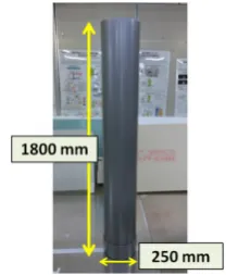
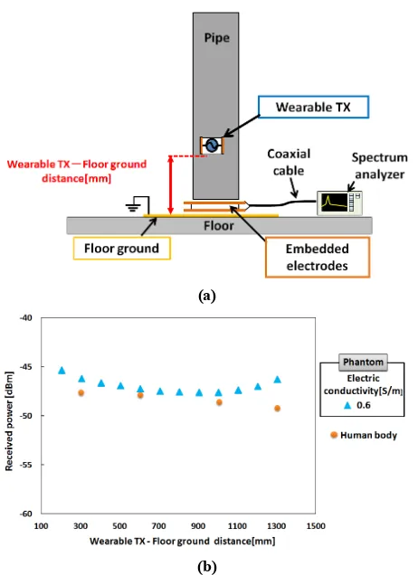
Phantoms, ones having the same electrical characteristics as the human body, were used in our experiments to obtain reproductive results constantly. Figure 4 shows a photograph of a phantom. Its outer shell is a polyvinyl chloride (PVC) pipe. The dimensions of the pipe were a diameter of 250 mm, a thickness of 8 mm, and a height of 1800 mm. The pipe was filled with salt water, the conductivity of which was adjusted to 0.6 S/m at 6.75 MHz (Human body: 0.6 S/m) [8]. The water level was 1500 mm. The relative permittivity of the water was 80. Figure 5 shows the experimental system and the results for evaluating the surface propagation of the main signal. The tendency of the surface propagation of the main signal in the phantom was almost the same as that in a human body. We also experimentally found that the electrical characteristics of the phantom were equivalent to those of the human body from the view of the antenna function for receiving radiation signals from other transmitters.
(a)
(b)
Figure 5. (a) experimental system to evaluate surface propagation of main signal (b) results of experiment.
3.
EXPERIMENTS AND RESULTS
We assumed a situation where a human stands on the embedded electrodes of a ticket gate and where another human wearing a wearable TRX stands behind the first human. We defined the phantom standing on the embedded electrodes as phantom 1 and the other phantom wearing a wearable TRX and standing behind phantom 1 as phantom 2. The human body is regarded as a conductor under 10 MHz. Therefore, the model was composed of seven conductors, such as a signal electrode (#1) and a ground electrode (#2) of the wearable TRX, a floor ground (#3), an embedded lower electrode (#4), an embedded upper electrode (#5), phantom 1 (#6), and phantom 2 (#7), as shown in Figure 6. We call this the signal interference model. Figure 7 shows the schematic of our experimental system. Phantom 1 and 2 were the same as the phantom shown in Figure 4. The battery-powered transmitter generates a sinusoidal wave at 6.75 MHz. We measured the received interference voltage with embedded electrodes while changing the distance between phantom 1 and 2.
The embedded electrodes were connected to a
measurement instrument, and its dimensions were 350 x 350 mm. An 8-mm-thick polyethylene plate was inserted between the electrodes. The floor ground was connected to the power source ground of the AC resource, which was distinguished from the earth ground and measured to be 2000 x 3000 mm. We evaluated the interference signal loss, which was represented by the ratio of the received interference voltage to the transmitted interference voltage defined as
interference signal loss
= − 20 × log transmitted interference voltage dB 1.received interference voltage
Figure 8 shows the interference signal losses that were calculated from the experiment results. The closer the distance between phantom 1 and 2 became, the stronger the interference signals were. These results revealed that the signal interference depends on the distance between phantom 1 and 2.
Figure 6. Signal interference model using seven conductors.
Figure 7. Schematic of experimental system.
4.
SIMULATION
4.1
Equivalent circuit
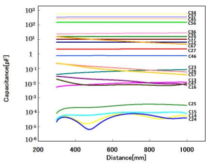
An equivalent circuit of signal interference model is represented by capacitances because conductors are capacitively coupled with each other in the NFCC system [9, 10]. The capacitances between seven conductors were calculated in the 3D electromagnetic field simulation. Figure 9 shows the structures for the simulation. The materials of the conductors were set to copper in the simulation. As shown in Figure 10, these capacitances were applied to the lumped-parameter equivalent circuit for the signal interference model. The conductors shown in Figure 6 are represented as nodes in the equivalent circuit. Figure 11 shows the simulation results of the capacitances according to the change in the distance between phantom 1 standing on the embedded electrodes and phantom 2 wearing the TX.
Figure 9. Structures in electromagnetic field simulation.
Figure 10. Lumped-parameter equivalent circuit.
Figure 11. Dependence of capacitance values between seven conductors on the distance between phantom1 and 2.
4.2
Simplified equivalent circuit
We analyzed the mechanism of the signal interference in the simplified equivalent circuit to find how to suppress it. The simplified circuit was designed in consideration of the capacitance change due to the differences in the distance between phantom 1 and 2. We calculated the capacitances between each of the nodes in the equivalent circuit with the 3D electromagnetic field simulator. With these simulation results, we simplified the original circuit as follows. We omitted C13, C14, C15, C23, C24, C25, C47, and
C57, which were below the capacitances 1 pF because they were
smaller than other capacitances. But C26 was not omitted because
it was one of the capacitances which comprised the main interference signal path of the equivalent circuit. We also omitted C35 because the value of C35 was much smaller than the value of
the series of C34 and C45. In addition, we continuously omitted C46
because the value of C46 was much smaller than the value of the
series of C45 and C56. Simplified circuit A was proposed with all
these omissions. We also obtained a further simple equivalent circuit, which is named simplified circuit B. Simplified circuit B consists of only C12, C17, C26, C35, C37, C45,and C56 representing
the main interference signal path. Figure 12 shows the equivalent circuits of simplified circuit A and B.
4.3
Evaluation of simplified circuits
We calculated the signal transmission for each of the original equivalent circuit and simplified circuit A and B with the circuit simulation software (LTspice: Linear Technology). With the calculated results, we evaluated the interference signal losses by the equation (1). When we evaluated the interference signal losses of the simplified circuit B, the equation (1) was expressed as
interference signal loss = − 20
× log
Z!
Z!jωC%&+ 1
1
jω (C1)*+ 1C+,+ 1C-%+ 1C-*+ 1C&,. +
Z!
Z!jωC%&+ 1
/
= − 20 × log Z Q
+,+ P dB. 2
The angular frequency is ω. The embedded electrodes (#4 and #5) are connected to a spectrum analyzer, and its input impedance is Z0 =50 Ω. The impedance of the capacitive coupling C26 is Z26
=1/ jωC+,. The impedances Q and P are expressed by Z0 and the
capacitances other than C26. On the other hand when we evaluated
the interference signal losses of the simplified circuit A, the equation (1) was expressed as
interference signal loss
= − 20 × log 2SZ Z+,+ R
+,++ TZ+,+ U 7 dB .
3
Here, the impedances R, S, T and U are given by Z0 and the
capacitances other than C26. Figure 13 shows the interference
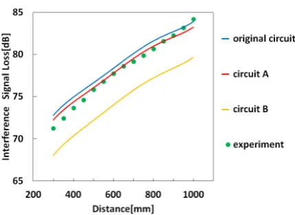
signal losses that were calculated from the original equivalent circuit and simplified circuit A and B. The experimental results are also shown in Fig. 13. To estimate the validity of simplified circuit A and B, we calculated the residual errors between the results of the original circuit and each result of the simplified circuits; moreover, we extracted the square root of the errors. Figure 13 shows that the tendency of simplified circuit A was qualitatively similar to the tendency of the experimental results. Also, the residual error of simplified circuit A was within 1 dB. These results revealed that the accuracy of simplified circuit A was high. On the other hand there was a large difference of 3.8 dB between the experiment and the calculation using circuit B. From these results, we proposed simplified circuit A as a signal interference analysis model.
Figure 13. Interference signal loss according to distance between phantom 1 and 2.
4.4
Main factor of signal interference
We considered the main factor of the signal interference from simplified circuit A. The main interference signal path of simplified circuit A consists of C12, C17, C26, C35, C37, C45,and C56.
The capacitances C12, C17, C35, C37, C45,and C56 are small changes
due to the distance between the two phantoms. However, capacitance C26 depends on the distance between the two
phantoms. The experimental results revealed that the interference signal in the model depends on the distance between the two phantoms. These revealed that capacitance C26 was the main
factor in the signal interference.
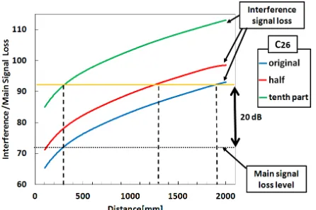
Figure 14 shows the interference signal losses of simplified circuit A of the original and half and one-tenth parts of the value of C26.
The S/N ratio of the NFCC system needs 20 dB to establish stable communication. This condition is equivalent to the condition where the ratio of the main signal loss to the interference signal loss is 20 dB in Figure 14. The main signal loss level of 72.5 dB is also shown in the figure. This value was the simulated result when the height of the wearable TRX was 1150 mm on the phantom. The interference signal loss should be larger than 92.5 dB to establish stable communication. Therefore, we defined the distance that the interference signal loss level was equal to 92.5 dB as the interference distance. The interference distance means the threshold distance to establish stable communication in the NFCC system. The interference distances of the original, half, and one-tenth parts of value were 1900 mm, 1300 mm, and 300 mm, respectively. These results revealed that the interference distance was shortened by reducing C26. We also found that the capacitive
coupling C26 of ground electrode (#2) of the wearable TRX and
Figure 14. Effect of interference signal loss by varying C26.
5.
CONCLUSIONS
We investigated the interfering mechanism in NFCC systems to mitigate the interference problem. We measured interference signal losses depending on the distance between two phantoms and proposed an equivalent circuit of the signal interference as an analytical model. From the model, we identified the main factor of signal interference, which was the capacitive coupling C26
between phantom 1 (#6) and ground electrode (#2) of a wearable TRX. To design a stable NFCC link, we need to weaken the coupling capacitance between of C26.
ACKNOWLEDGMENTS
Part of this work was supported by a Grant-in-Aid for Scientific Research (A) 23246073 from the Ministry of Education, Culture, Sports, Science and Technology of Japan.
REFERENCES
[1] T. G. Zimmerman. 1996. Personal Area Networks:
Near-field intrabody communication. IBM System. J, 35(3/4) 609-617.
[2] N. Cho, J. Yoo, S. J. Song, J. Lee, S. Jeon, and H. J. Yoo. 2007. The Human Body Characteristics as a Signal Transmission Medium for Intrabody Communication. IEEE Trans. Microwave Theory and Techniques. 55, 1080-1086. [3] A. Fazzi, S. Ouzonov, and J. v. d. Homberg. 2009. A
2.75mW Wideband Correlation-Based Transceiver for Body-Coupled Communication. IEEE ISSCC. 204-205. [4] J. Bae, H. Cho, K. Song, H. Lee, and H. J. Yoo. 2012. The
Signal Transmission Mechanism on the Surface of Human Body for Body Channel Communication. IEEE Trans. Microwave Theory and Techniques. 60, 582-593. [5] Y. Kado, T. Kobase, T. Yanagawa, T. Kusunoki, M.
Takahashi, R. Nagai, O. Hiromitsu, A. Hataya, H. Shimasaki, and M. Shinagawa. 2012. Human-Area Networking
Technology Based on Near-Field Coupling Transceiver 2012 IEEE Radio & Wireless Sym. (Santa Clara, California, USA, January, 2012). 119 - 122.
[6] M. Ishida, T. Nakamura, M. Nozawa, N. Watanabe, Y. Kado, and M. Shinagawa. 2014. MHz-Band RF Signal Propagation
Characteristics on Human-Equivalent Phantom for Intra-body Communication. EuCAP 2014. 2284-2288. [7] M. Ishida, T. Nakamura, M. Nozawa, N. Watanabe, Y. Kado,
and M. Shinagawa. 2014. MHz-Band RF Signal Propagation Characteristics on Human Body for Intra-body
communication. I2MTC 2014. 797-801.
[8] SGabriel, R.W.Lau and C.Gabriel. 1996. The dielectric properties of biological tissues: Ⅱ.Measurements in the frequency rage 10 Hz to 20 GHz. Phys. Med. Biol. 41, 2251-2269.
[9] N. Haga, K. Motojima, M. Shinagawa, Y. Kado. 2014. System of equations describing charges of multiple conductors immersed in electrostatic fields. IEICE Electronics Express. 11, no. 19.
[10]Y. Hayashida, R. Sugiyama, Y. Ido, A. Suzuki, Y. Takizawa, M. Shinagawa, Y. Kado, and N. Haga. 2014. Capacitance Model of Embedded Transceiver for Intra-body