© 2017 IJRAR July 2017, Volume 4, Issue 3 www.ijrar.org (E-ISSN 2348-1269, P- ISSN 2349-5138)
Design of Micro Channel Heat Sink
Pappuri Hazarathaiah*, Assistant Professor, Y.Ashok Kumar Reddy, Associate Professor, and S.Indumati, Professor, Department of Mechanical Engineering, N.B.K.R. Institute of Science and Technology, Vidyanagar
Andhra Pradesh, India - 524 413
Abstract—Microchannels are of current interest for use in com- pact heat exchangers, microbiochips, micro reactors, VLSI system where very high heat transfer performance is desired.These electronic equipments are virtually synonyms with modern life applications such as appliances, instruments and computers. The dissipation of heat is necessary for the proper functioning of these instruments Microchannels provide very high heat transfer coefficients because of their small hydraulic diameters. Here, an investigation of fluid flow and heat transfer in microchannels is conducted. Fluid flow and heat transfer experiments were conducted on a silicon microchannel heat exchanger (MHE) .A three-dimensional Computational Fluid Dynamics (CFD) model was built using the commercial package, FLUENT, to investigate the conjugate fluid flow and heat transfer phenomena in a silicon based rectangular microchannel heat sink. This work focused on laminar flow (Re ¡ 200) within rectangular microchannel with hydraulic diameter 86m for single-phase liquid flow.The influence of the thermophysical properties of the fluid on the flow and heat transfer, are investigated by evaluating thermophysical properties at a reference bulk temperature.
The micro-heat sink model consists of a 10 mm long silicon substrate, with rectangular microchannels, 57m wide and 180m deep, fabricated along the entire length. water at 293K is taken as working fluid. The results indicate that thermophysical properties of the liquid can significantly Influence both the flow and heat transfer in the microchannel. Assumption of hydrodynamic, fully developed laminar flow is valid here on basis of Langhaars equation. The local heat transfer coefficient and averaged Nusselt number is calculated and plotted for pressure drop of 50kpa, 30kpa and 10kpa.also result is verify for heat flux 50W/cm2, 90W/cm2and 150 W/cm2.
Keywords—Micro Channel Heat Sink, ANSYS Models
I. INTRODUCTION
In present study a numerical model with fully developed flow is presented and used to analyze three dimensional microchannel heat sink for Re numbers (¡ 160 with hydraulic diameter 86 m). In the current investigation, three different cases (qw=90 W/cm2, p= 50kpa, 15kpa, and 10kpa) were considered .we examine it for heat flux for 50 W/cm2,90
W/cm2 and 150W/cm2 . The average Nusselt number is carefully defined and after a series of calculations for different total pressure drops in the channel the relation between the Nusselt number and the Reynolds number is analyzed and plotted The numerical model is based on three dimensional conjugate heat transfer.
FLUENT, a commercial package employs continuum model of Navier Stokes with SIMPLE algorithm, is used for this
investigation. The numerical solver codes are wellestablished and thus provide a good start to more complex heat transfer and fluid flow problems. FLUENT provides adaptability to variation of thermo physical properties with respect to tem- perature effect. The thermo physical properties are chosen at a reference temperature A series of calculations were carried out to analyze rectangular silicon-based microchannel heat sink with a geometry Computations were performed for different total pressure drops in the channel to obtain the relation between the overall averaged Nu number and the Re number for this specific geometry of heat sinks.
A fan often aids a heat sink by providing increased airflow over the heat sink thus maintaining a larger temperature gradient by replacing the warmed air more quickly than passive convection achieves alone this is known as a forced air system. If a fan is specified for a system, pressure drop, volumetric flow rate and flow cross sectional area also become system constraints. Otherwise they are the design parameters.
Pressure drop :- Pressure drop is the resistance to the air movement and it is related with flow cross sectional area, fin spacing and fin length. The heat sink should be designed so as to yield a smaller pressure drop than the static pressure of the fan. The heat sink selected or designed changes the total pressure drop of the system, although it is not a very major difference, the operating point which is the intersection of the system impedance curve and the fan impedance curve may shift.
Volumetric flow rate :- Volumetric flow rate is the velocity times the cross sectional area of the flow. Velocity magnitude of the incoming air is the dominant factor creating turbulence. Therefore if the fan is specified, the velocity of the air and the flow regime are known. Flow inlet velocity as a design parameter is also surveyed in the literature. Increasing the flow inlet velocity thus the volumetric flow rate, which results in turbulence, the thermal resistance may be reduced by 35 percent compared to the same geometry with laminar flow.
Flow cross sectional area :- Flow cross sectional area is known as long as the fan dimensions are known. Designing a heat sink with a smaller cross sectional area than the flow area creates the by-pass of air. Since some of the air delivered by the fan will not participate in the heat transfer, efficiency is reduced. Ducting the coolant fluid to and from the heat sink through tubes, it is demonstrated that larger heat removal capabilities are achievable as the by-pass of air is prevented.
II. LITERATURE REVIEW
from conventional theory. Peng and Peterson found disparities between conventional flow theory and experimental results for microchannels. They tested microchannels with hydraulic diameters ranging from 133 µ m to 367 µm, and they showed a friction factor dependence on hydraulic diameter and channel aspect ratio [4].
Judy [5] did pressure drop experiments on both round and square microchannels with hydraulic diameters ranging from 15 to 150 µm. They tested distilled water, methanol and iso propanol over a Reynolds number range of 8 to 2300. Their results showed no distinguishable deviation from laminar flow theory for each case.
Liu and Garimella [6] conducted flow visualization and pres- sure drop studies on microchannels with hydraulic diameters ranging from 244 to 974 µm over a Reynolds number range of 230 to 6500. They compared their pressure drop measurements with numerical calculations. Computations were performed for different total pressure drops in the channel to obtain the relation between the overall averaged Nu number and the Re number for this specific geometry of heat sinks.
Choi [7] also suggested by their experiments with mi- crochannels inside diameters ranging from3 to 81m that the Nusselt number did in fact depend on the Reynolds number in laminar microchannel flow. Experimental measurements for pressure drop and heat transfer coefficient were done by Rahman [8] he use water as a working fluid and tests are conduct on channel of different depths.
With the advancements of computing in the past few decades, electronics have become faster, smaller, and more powerful, resulting in an ever-increasing strain on the devices cooling system. Dr. Gordon Moore stated that, semi-conductor transistor intensity, and hence performance, doubles roughly every 18 months , meaning that the amount of heat requiring dissipation proportionately increases [9]. This observation can be seen in the majority of todays personal computers (PC) chips. In most cases, the chips are cooled through the use of forced air convection fans . However, when dealing with components that contain billions of transistors, working at high frequencies (a few GHz), temperatures can reach critical levels where standard-cooling methods are not sufficient. In an
effort to improve methods for high heat flux cooling, liquids were forced through micro-channels manufactured within the component.
Mainfold microchannel heat sinks were first suggested by choi and Barron [10] and numerically studied by Rahman and Fedorov [9]. Compared to conventional microchannel heat sinks, manifold microchannel heat sinks feature many inlet and outlet manifolds, alternating at a periodic distance along the length of the microchannels. Coolant flows from the inlet port in to the manifolds and forms separate streams. Each stream flow through a short section of microchannels. If fully developed laminar flow fixed flow rate are assumed, at the pressure drop is reduced by a factor equal to the number of manifold inlet/outlet compared with conventional microchan- nel heat-sink, on the other hand the same temperature variation exists for manifold microchannel in a much shorter distance. There are also concerns on the heat transfer efficiency for the region underneath the manifolds.
Assuming fully developed conditions, Le [11] conducted an optimization study to minimize the temperature gradient and the maximum temperature for microchannel heat sink. It was demonstrated that further reduction in maximum temperature and temperature gradient could be achieved by verying the cross-sectional dimensions of the microchannel. The penalty of this method is the dramatically increased pressure drop due to the acceleration along the flow direction.
J. Li and G.P. Peterson [12] numerically simulated a forced convection heat transfer occurring in silicon based micro channel heat sinks has been conducted using a simplified three- dimensional conjugate heat transfer model (2D fluid flow and 3D heat transfer) consists of a 10 mm long silicon substrate, with rectangular micro channel, 57 m wide and 180 m deep, fabricated along entire length with hydraulic diameter 86 m. The influence of the geometric parameters of the channel and thermo physical properties of the fluid on the flow and the heat transfer, are investigated using temperature dependent thermo physical property method. Result indicates that this properties of the liquid can significantly influence both the flow heat transfer in the micro channel heat sink. The result indicates that the variations in the way the Nusselt number is defined may results in different conclusions even using the same experimental data. Then compare the numerical results with other published numerical results and experimental data available in literature.
Modeling of transport in micro channels can be divided in to two categories. In the first, method used for macro-scale channels are directly implemented to evaluate the performance of micro channel heat sinks. In the second category, new effects are taken into account to explain the deviation of the measured results from classical theory. The former range from simple 1- D models to three dimensional conjugate studies (Weisberg and Bau [13],Yin and Bau[14], Fedorov and Visakanta [9] . However, existing analytical studies are still inconclusive.
III. MICRO CHANNEL HEAT SINK
© 2017 IJRAR July 2017, Volume 4, Issue 3 www.ijrar.org (E-ISSN 2348-1269, P- ISSN 2349-5138)
A. Design Parameters
The design parameters include the heat sink material, the number and geometry of the fins and their alignment and the base plate thickness as shown in Fig. 1. In order to obtain the minimum thermal resistance and pressure drop, each of these parameters must be designed well.
Fig. 1. Heat Sink Design Parameters
B. Heat Sink Materials
Heat sinks are made from a good thermal conductor such as copper or aluminum alloy. Copper (401 W/m K at 300 K) is significantly more expensive than aluminum (237 W/m K at 300 K) but is roughly twice as efficient as thermal conductor. Aluminum has the significant advantage that it can be easily formed by extraction, thus making complex crosssections possible. Aluminum is also much lighter than copper, offering less mechanical stress. on delicate electronic components. Some heat sinks made from aluminum have a copper core as a trade off as in Swiftech 462-A heat sink . Although the thermal conductivity of zinc is lower compared to that of aluminum and copper, it may also be a good material for electronic cooling purposes Figure (1.7). When zinc added to an alloy, it eliminates porosity in the casting process, which is an advantage over aluminum and copper since they are not pore free after the casting.
C. The Number of Fins
A heat sink usually consists of a base with one or more flat surfaces and an array of comb or fin-like protrusions to increase the heat sink’s surface area contacting the air, and thus increasing the heat dissipation rate. In Fig (1.8) Cu MHE with channels molded, plenums cut, and holes drilled is measured in micro level.
It is one of the most important factors for heat sink per- formance. A heat sink designed for electronics cooling is a
Fig. 2. Thermal conductivities of common heat sink materials and possible candidates
compact heat exchanger for which the ratio of heat transfer area to occupied volume is very large. Therefore increasing the number of fins provides more area for heat transfer. Increasing the number of fins from 238 to 294, Hedgehog increased the heat transfer area by 8.4 percent and approximately 10 percent efficiency is assured in the succession of Hedgehog-238M to Hedgehog-294M. However, it should be noted that increasing the number of fins creates an adverse effect, which is the increased static pressure drop. In order to overcome higher pressure drops, higher pumping powers are needed, which requires the installation of more powerful fans or blowers.
Fig. 3. Cu MHE with channels molded, plenums cut, and holes drilled
D. Fin Shapes
Fig. 4. Two Heat Sinks with different fin geometry
E. Other Parameters
A fan often aids a heat sink by providing increased airflow over the heat sink thus maintaining a larger temperature gradient by replacing the warmed air more quickly than passive convection achieves alone this is known as a forced air system. If a fan is specified for a system, pressure drop, volumetric flow rate and flow cross sectional area also become system constraints. Otherwise they are the design parameters.
Pressure drop :- Pressure drop is the resistance to the air movement and it is related with flow cross sectional area, fin spacing and fin length. The heat sink should be designed so as to yield a smaller pressure drop than the static pressure of the fan. The heat sink selected or designed changes the total pressure drop of the system, although it is not a very major difference, the operating point which is the intersection of the system impedance curve and the fan impedance curve may shift.
Volumetric flow rate :- Volumetric flow rate is the velocity times the cross sectional area of the flow. Velocity magnitude of the incoming air is the dominant factor creating turbulence. Therefore if the fan is specified, the velocity of the air and the flow regime are known. Flow inlet velocity as a design parameter is also surveyed in the literature. Increasing the flow inlet velocity thus the volumetric flow rate, which results in turbulence, the thermal resistance may be reduced by 35 percent compared to the same geometry with laminar flow.
Flow cross sectional area :- Flow cross sectional area is known as long as the fan dimensions are known. Designing a heat sink with a smaller cross sectional area than the flow area creates the by-pass of air. Since some of the air delivered by the fan will not participate in the heat transfer, efficiency is reduced. Ducting the coolant fluid to and from the heat sink through tubes, it is demonstrated that larger heat removal capabilities are achievable as the by-pass of air is prevented.
IV. MATHEMATICAL FORMULATION
Here the micro-heat sink model consists of a 10 mm long substrate and dimension of rectangular microchannels have a width of 57 m and a depth of 180 m as shown in Fig (3.1). The heat sink is made from silicon and water is used as the cooling fluid. The electronic component is idealized as a constant heat flux boundary condition at the heat sink bottom wall. Heat transport in the unit cell is a conjugate problem which combines heat conduction in the solid and convective heat transfer to the coolant (water).Here we consider a rectangular
channel of dimension (900x100mx10mm) applied constant heat flux of 90W/cm2 from bottom as given table(1). Water flowing through channel at temperature 293k on account of pressure loss of 50kpa the model in this study uses a unit grid dimension of 99X90X10 as in Fig (3.2).
Here we assumed to have a constant heat flux, q(90W/cm2 )at the bottom wall .The other wall boundaries of the solid region are assumed perfectly Insulated with zero heat flux. The water flow velocities are taken from different Reynolds numbers, from 96 to 164, with reference to the hydraulic diameter of 86 m.
A. Description Of The Designed Cooling Model
© 2017 IJRAR July 2017, Volume 4, Issue 3 www.ijrar.org (E-ISSN 2348-1269, P- ISSN 2349-5138)
×
Fig. 5. Geometric dimensions of single channel
B. Assumptions
* Laminar flow.
* Uniform wall heat flux.
* Negligible radiation heat transfer * Constant heat flux 9 105 * Incompressible fluid
* Variable thermo physical properties
In this paper the fundamental governing equations are con- tinuity, momentum and energy equations which are derived from basic principles of heat and fluid flow. The equations are posed to implement SIMPLE (Semi-Implicit Method for Pressure Linked equation) algorithm. Consequently the Navier- Stokes equations are solved.
V. RESULTS
A series of numerical calculations have been conducted by fluent and the results are presented in order to show the effects of heat flux and mass flow rate on the temperature distribution in the microchannel heat sinks. The results are de- voted to the local temperature distribution in micro-heat sinks, the average bulk characteristics of heat transfer, and further general discussion. Furthermore, in order to better compare the computational results obtained here with the experimental data available in the literature, the average overall Nusselt number is defined and analyzed with respect to the variations in the Reynolds number. Here the thermal properties of water were chosen at a reference temperature. Because the thermophysical properties are temperature dependent, particularly the liquid viscosity, the velocity and consequently the Reynolds numbers are different under the same pressure drop conditions.
As discussed previously, the thermophysical properties of the liquid are based upon the estimated liquid bulk temperature .For ∆p =50kpa and 90W/cm2 variation in the reference tem-
perature from 200C to 320
C, changes the mean velocity from 1.12 to 1.38 m/s, and results in a corresponding change in the Reynolds number from 99 to 146.here reference temperature is taken 320C.
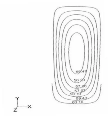
A. Temprature contour
The temperature of the liquid at the inlet is initially uni- form (at 200C). The temperature Profiles shown is due to the assumption of hydrodynamic fully developed Flow .It is interesting to note that the temperature is highest at the channel corner. This is due to the low velocity of the flow and maximum temperature of fluid at exit of channel. The reference temperature for the thermophysical properties of water was chosen as TRef= Tin+Tout . The principal issues in heat sink
underway to actually measure the temperature and pressure gradients in these microchannels It is apparent here that the asymptote, average Nusselt number 4.1 lies between the values for a constant axial wall heat flux, 4.8, and a constant axial wall temperature, 4.0, for fully developed laminar flow in ducts, of rectangular cross-section with approximately (W: H = 1: 3). The silicon conducts more heat through the channel walls results temperature rise of water from 293K to 309K. From, this observation it is evident that the silicon material of heat sink is more useful and efficient to dissipate heat from the electronics chips. For prediction of fluid flow and thermal characteristics ,contour of temperature in the fluid at the inlet and outlet of channel is shown in Fig.7.
Fig. 6. local temperature distribution in X-Y plane at X=50µ m for ∆p=50 kpa
and heat flux 90 W/cm2
Fig. 7. Temperature contour of Silicon material at X = 50µm for ∆p=50 kpa
and heat flux 90 W/cm2at outlet
Here we consider the Pressure difference of 10kpa and heat flux of 90W/cm2. It is evident from Fig. 10 due to less Velocity the fluid get sufficient time to heat up so highest temperature obtained in this case. Further we see pressure drop of 15 kpa and heat flux 90W/cm2 and pressure drop of 50kpa and heat flux 90W/cm2 are shown in the Fig.11 and Fig. 12 respectively.
For further analysis we take constant pressure drop of 50kpa
2
Fig. 8. Temperature of Outlet at Adiabatic wall conditions for double parallel channel
Fig. 9. Temperature contour at Isothermal (300k) wall condition for parallel channel
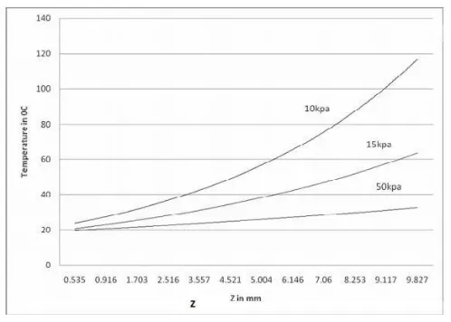
In the current investigation, three different cases ( q”= 90
W/cm2 ,∆p =50kpa, 15kpa and 10 kpa) were considered here and local temperature distribution along the channel length was shown in Fig.16.Here the maximum temperature rise in case of 10kpa because the flow of fluid is very slow so fluid get sufficient time to heat up.
Fig.13, Fig.14 and Fig. 15 displays the filled contours of temperature at outlet of the micro-channel for heat fluxes of 50
W/cm2, 90 W/cm2 and 150 W/cm2 at a pressure difference of
50 kpa. As the heat flux increases, the outlet temperature goes on increasing because the fluid gets heated up more and more due to convective heat transfer which is evident from the contour profiles Fig.16 and Fig.17 displays the temperature at outlet of the micro-channel for heat fluxes of 50, 90 and 150 W/cm2 at a pressure difference of 50 kpa. As the heat flux increases, the outlet temperature goes on increasing because the fluid gets heated up more and more due to convective heat transfer which is evident from the contour profiles.
T150 > T90 > T50 (At 50 kpa)
Fig. 10. Temperature contour of fluid at outlet for Pressure difference of
10kpa and heat flux of 90W/cm2
Fig. 11. Temperature contour of fluid at outlet for Pressure difference of 15
© 2017 IJRAR July 2017, Volume 4, Issue 3 www.ijrar.org (E-ISSN 2348-1269, P- ISSN 2349-5138)
Fig. 12. Temperature contour of fluid at outlet for Pressure difference of
50kpa and heat flux of 90W/cm2
Fig. 13. Temperature contour of fluid at outlet for Pressure difference of
50kpa and heat flux of 50 W/cm2at X=50µm
B. Velocity Contour
Velocity contour at outlet of channel for pressure difference of 50kpa and heat flux of 90 W/cm2 shown in Fig.17
C. Average heat transfer coefficient
The variation of heat transfer coefficient is shown in Fig.18. It is found that the heat transfer coefficient sharply decreases at 1/10th of micro-channel. For this the temperature is also found less at the entrance region of water.
D. Average Nusselt Number
Here we plot the average heat transfer variation for different
Fig. 14. Temperature contour of fluid at outlet for Pressure difference of 50kpa
and heat flux of 90 W/cm2
Fig. 15. Temperature contour of fluid at outlet for Pressure difference of 50kpa
and heat flux of 150 W/cm2
by results here that the average Nusselt number 4.1 obtained here lies between the values for a constant axial wall heat flux, 4.8, and a constant axial wall temperature, 4.0, for fully developed laminar flow in ducts, of rectangular crosssection with approximately [W: H = 1: 3 (57:180)].
It is clear that if the definitions for the heat transfer coefficient and Nusselt number are used; the heat transfer will be underestimated at the entrance portion of the channel (especially close to the inlet) and overestimated towards the end of the channel. Here we do not consider either the heat conduction in the substrate and the conjugate heat transfer influence on the local heat flux variation along the longitudinal direction.
k
Fig. 16. Average temperature of liquid for different pressure drops and
constant heat flux 90 W/cm2at X=50µm
Fig. 17. Velocity contour at outlet of channel for pressure difference of 50
kpa and 90 W/cm2
Fig. 18. Average heat transfer coefficient variation along channel for for
Pressure difference of 50 kpa and heat flux of 90 W/cm2
developed here. The average Nusselt number is simply defined as hDh .
The average heat transfer coefficient variation and the av- erage Nusselt number variation for these three cases can be
Fig. 19. Average heat transfer coefficient variation for different pressure drop
(50kpa,15kpa, 10kpa) at q”= 90 W/cm2at X=50µm
Fig. 20. Average Nusselt number variation for different pressure drop
(50kpa,15kpa, 10kpa) at 90 W/cm2at X=50 µm
determined and are shown in Fig.20 .The natures of output results are comparable with conventional results. From these two figures it can be concluded that the variations of the heat transfer coefficient and the Nusselt number along the flow direction is quite small for this type of microchannel heat sink after the thermal entrance lengths. It should be noted that since the grid size in the flow direction is relatively coarse, the local heat transfer is not as accurate or detailed as the case for the y- and x-direction. However the resolution is sufficient to aid in the design of micro heat sinks for industrial applications and also to provide information and insight in to the fluid flow characteristics in the flow direction.
Here we plot the average heat transfer coefficient variation along the channel length for different heat flux of magnitude 50
W/cm2, 90 W/cm2and 150 W/cm2 in Fig.21.
E. Nusselt number variation for different heat flux
Here we plot the Nusselt no variation along the chan- nel length for different heat flux of magnitude 50 W/cm2, 90
© 2017 IJRAR July 2017, Volume 4, Issue 3 www.ijrar.org (E-ISSN 2348-1269, P- ISSN 2349-5138)
Fig. 21. Axial variation of average heat transfer coefficient for different heat fluxes at ∆p=50kpa
Fig. 22. Axial variation of Nusselt number for different heat fluxes at
∆p=50kpa
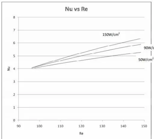
F. Reynolds Number Vs Nusselt Number
he average Nusselt number corresponding to their Reynolds number for different pressure drop at constant heat flux are plotted in Fig.23 In order to compare the experimental results with the simulation results, we considered different Prandtl number of water for different Reynolds number. Comparisons between the simulated results and the experimental results are plotted in Fig.24 The error is estimated to be 3 percent which is less than 5 percent so acceptable.
VI. CONCLUSION
The analysis performed, provides a fundamental understand- ing of the combined flow and conjugate convectionconduction heat transfer in the three-dimensional micro-channel heat sink. The model formulation is general and only a few simplifying assumptions are made. Therefore, the results of the analysis as well as the conclusions can be considered as quite general
Fig. 23. Comparison between Nusselt number vs Reynolds number for and
different heat flux of 50 W/cm2, 90 W/cm2and 150 W/cm2at ∆p=50kpa
Fig. 24. Variation of Reynolds no vs Nusselt no in experimental work and simulated work
and applicable to any three-dimensional conjugate heat transfer problems.
A three-dimensional mathematical model, developed using incompressible laminar NavierStokes equations of motion, is capable of predicting correctly the flow and conjugate heat transfer in the micro-channel heat sink. It has been validated using experimental data reported in the literature, and a good agreement has been found between the model predictions and measurements.
recirculation zones in the highly conducting silicon substrate where the fluid and solid are in direct contact. Here we have compare of the numerical results with other published results and experimental data available in the literature for Reynolds numbers less than 200 based on a hydraulic diameter of Dh = 86 m. The influence of the geometric parameters of the channel and the thermophysical properties of the fluid on the flow and the heat transfer, are investigated with a temperature dependent thermophysical property. A correlation for the averaged Nusselt number with the Reynolds number is developed and discussed. The results indicate that variations in the way the Nusselt number is defined in different conditions. As with the increase in pressure drop ,flow velocity as well as Reynolds number increase hence Nusselt number increases in consistence with Reynolds number analogy
The local heat fluxes from the solid to the coolant in the small inlet region of the micro-channel are larger than those in the further downstream portion by more than two orders of magnitude. This is because the average convective heat transfer coefficient is much larger in the upstream locations (the boundary layer thickness is small) and also because the highly conducting channel walls support very effective heat re- distribution from the downstream (large convective resistance) to the upstream (small convective resistance) regions of the channel. This finding supports the concept of the manifold micro-channel (MMC) heat sink where the flow length is greatly reduced to small fraction of the total length of the heat sink by using a design with multiple inter-connected inlets and outlets.
The result shows average Nusselt number increases with increase in pressure drop as well as heat flux.
REFERENCES
[1] S. G. Kandlikar and W. J. Grande, “Evaluation of single phase flow
in microchannels for high heat flux chip coolingthermohydraulic
performance enhancement and fabrication technology,” Heat transfer
engineering, vol. 25, no. 8, pp. 5–16, 2004.
[2] J.-Y. Jung and H.-Y. Kwak, “Fluid flow and heat transfer in microchan-
nels with rectangular cross section,” Heat and Mass Transfer, vol. 44, no. 9, pp. 1041–1049, 2008.
[3] N. Obot, “Toward a better understanding of friction and heat/mass trans-
fer in microchannels–a literature review,” Microscale Thermophysical
Engineering, vol. 6, no. 3, pp. 155–173, 2002.
[4] S. Mehendale, A. Jacobi, and R. Shah, “Fluid flow and heat transfer at
micro-and meso-scales with application to heat exchanger design,”
Applied Mechanics Reviews, vol. 53, no. 7, pp. 175–193, 2000.
[5] J. Judy, D. Maynes, and B. Webb, “Characterization of frictional pressure
drop for liquid flows through microchannels,” International Journal of
heat and mass transfer, vol. 45, no. 17, pp. 3477–3489, 2002.
[6] D. Liu and S. V. Garimella, “Investigation of liquid flow in microchan-
nels,” Journal of Thermophysics and heat transfer, vol. 18, no. 1, pp. 65–72, 2004.
[7] Q. Weilin, G. M. Mala, and L. Dongqing, “Pressure-driven water flows
in trapezoidal silicon microchannels,” International journal of heat and
mass transfer, vol. 43, no. 3, pp. 353–364, 2000.
[8] M. M. Rahman, “Measurements of heat transfer in microchannel heat
sinks,” International Communications in Heat and Mass Transfer, vol.
27, no. 4, pp. 495–506, 2000.
[9] P. Kumar, Numerical Investigation of Fluid Flow and Heat Transfer in
Microchannel. PhD thesis, 2009.
[10] A. G. Fedorov and R. Viskanta, “Three-dimensional conjugate heat
transfer in the microchannel heat sink for electronic packaging,” Inter-
national Journal of Heat and Mass Transfer, vol. 43, no. 3, pp. 399–415, 2000.
[11] A. Bejan, “A study of entropy generation in fundamental convective heat
transfer,” Journal of heat transfer, vol. 101, no. 4, pp. 718–725, 1979. [12] J. Li, G. Peterson, and P. Cheng, “Three-dimensional analysis of heat
transfer in a micro-heat sink with single phase flow,” International Journal of Heat and Mass Transfer, vol. 47, no. 19-20, pp. 4215–4231, 2004.
[13] K. K. Ambatipudi and M. M. Rahman, “Analysis of conjugate heat
transfer in microchannel heat sinks,” Numerical Heat Transfer: Part A:
Applications, vol. 37, no. 7, pp. 711–731, 2000.
[14] H.-P. Zhou, P. Wang, L.-X. Zheng, W.-Q. Geng, J.-H. Yin, X.-P. Gan,