Stress & strain analysis of mobile tower
crane (luffing jib) using finite element
method
1
Atul shanker suman, 2Jyoti vimal, 3Vedansh chaturvedi 1
Research Scholar, 2Asst. Professor, 3Asst. Professor Department of Mechanical Engineering
Madhav Institute of Technology & Science, Gwalior, Madhya Pradesh 474005 Email: [email protected], [email protected], [email protected],
ABSTRACT
In present scenario, infrastructure is a basic need for the development of any country. The tower crane plays a vital role in the infrastructure field. The failure of the tower crane may be occur during loading & unloading due to failure of, its design. Tower crane are use to lift and carry heavy materials. This study focus on the prevention of crane damage which occur due to heavy load.
In this study, by using the SOLID WORKS-12 software the crane parts material which is made by plain carbon steel is modeled one-by-one, with specific dimensions. Afterwards the stress distribution analysis & the deformation analysis are done by SOLID WORKS-12 software. As the conclusion the safe design of mobile tower crane for 900 at a load of 800 kg on a different length of jib is recommended.
Key words: Mobile tower crane (luffing jib), plain carbon steel, SOLIDWORK-12, INTRODUCTION
Mobile tower crane are the self erecting/self folding tower crane. Operation can be easily affected by a single operator, through a remote control pod. This crane is mounted on a towable type trailer with compact dimensions for easy transportation. To minimize the dead weight for long distance transportations the counter weight box is designed with trap doors to enable general ballast use as a counter weight. The chassis design enables a short turning radius & easy positioning. Stabilizers are out & down type and can be reiterated into the lower chassis to satisfy the road clearance codes. An optional prime mover with a built in 20KVA generator makes. Mobile tower crane totally independent of any outside electric source and have separate carrier vehicle. The crane uses only a part of the power & generator can be used for other site equipment like mixers, vibrators & job site lighting system. Some mobile tower crane is controlled by a remote. This facilitates the operator position himself in such way that he can see both picking as well as dumping points for precise load & positioning.
In this study, a mobile tower crane is modeled in 3D using SOLIDWORK-12 computer software. Then, the generated components are meshed in SOLID WORKS-12 software. The meshed components are mounted on each other and the meshed model of the tower crane is obtained. Finite element analysis is accomplished considering the load combination in FEM norms.
MAIN BODY
Model Reference
Figure:
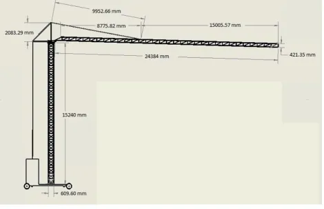
Figure 1: Pr
2 front & top vie
Mater
Yield
Tensi
Elasti
Poisso
Mass
Shear
Therm coeffi
roperties of plain
ew of the luffing j
M rial name
strength
ile strength:
ic modulus
on's ratio:
density
r modulus
mal expansio icient
n carbon steel
jib modeled in so
Properti
Material prop
Plain Ca
2.20594e
3.99826e
2.1e+011
0.28
7800 kg/
7.9e+010
n 1.3e-005
olid work
ies
perty
arbon Steel
e+008 N/m^2
e+008 N/m^2
1 N/m^2
g/m^3
0 N/m^2
5 /Kelvin 2
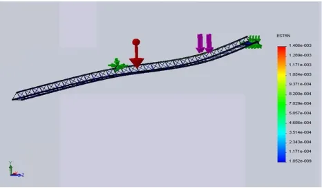
RESULT
Stress an
T & DISCUS
nalysis
SSION
Figure 4: final
Figure: (a): 800
l view of the mob
kg applied at the
bile tower crane
By the an In figure shown th In figure
nalysis of the (a) the analy hat the stress (v e (b) the analy
F
mobile tower ysis shown tha von mises) ge ysis shown th
Figure: (b): 800
Figure: (c): 800 k
jib using SOL
at whenever th enerated throu hat whenever t
kg applied at the
kg applied at the b
LID WORKS-1
he load (800k ughout the leng
the load (800
e middle of the jib
beginning of the j
12 software th kg) is applied gth of the jib i 0kg) is applied
b
ib
he above figur on the corner is 15421.5 N/m d on the midd
re shown that… r of the jib th /m2.
dle of the jib …
In figure (von mis In above the begin
Strain a
(c) the analy es) generated
result shown nning of the le
analysis
sis shown tha through the le n at constant lo ength.
at whenever th ength is 694.1 oad i.e. 800kg
Figure: (d): 800
Figure: (e) 800 k
he load (800kg 1 N/m2.
g the stress di
kg applied at the
kg applied at the
g) is applied o istribution is m
e corner of the jib
middle of the jib
on the beginn maximum at c
b
ning of the jib corner and mi
The strain In figure shown th In figure generated In figure generated Conclusi The cons middle, a for stress And it’s m The resul applied a jib. This con carried ou Referenc [1] Kazuy CRAN 820 [2] Lanfe of Me [3] Ismai of ma [4] Nenad proce [5] Vivia (2011
n analysis of t (d) the analy hat the strain g e (e) the analy d through the (f) the analys d through the
ion
stant load of and beginning s shown that t minimum whe lt for strain sh at the corner o nclusion suppo
ut by the begi
ce
ya ITOH, Naoak NE IN SOFT CL
eng Yu, 2007 “CA echanical Science il gerdemeli, serp achinery and asso d D. Zmic, Srda edia engineering 1 an W.Y. Tam, Iva 1) 208–215.
F
the mobile tow ysis shown tha generated thro
ysis shown th length is 4.54 sis shown tha length is 1.85 800 kg is app g. The SOLID
the stress gene en load applie hown that, the of the jib and s ort the genera inning of the j
ki SUEMASA, S
LAY” 13th World
ALCULATION M e and Technology
il kurt, okan delik ociated technology an M. Bosnjak,
10 (2011) 2238–2
an W.H. Fung 20
Figure: (f) 800 kg
wer jib using S
at whenever th ughout the len at whenever t 42e-009.
t whenever th 2e-008. plied on the m D WORK 12 is
erated through ed at the begin e strain genera strain generati al material han
ib length and
Satoshi TAMAT Conference on E
METHOD AND y 22 (2008) 829~8
katas, “FINITE E y, TMT2010, Me Valda M. Gasic
2243.
010 “TOWER CR
g applied at the b
SOLID WORK
he load (800k ngth of the jib the load (800 he load (800kg
mobile tower s used for ana hout the lengt nning of the jib
ation througho ion is minimu ndling practic minimum loa
TE 2004 “DYNA Earthquake Engin CONTROL VAL 834 ELEMENT ANA editerranean, 11-1 c, 2011“FAILUR RANE SAFETY
eginning of the ji
KS-12 softwar kg) is applied b is 6.539e-008 0kg) is applied g) is applied o
r crane jib at alysis of the v th is maximum
b.
out the length um when the lo
ce of the towe ad is carried ou
AMIC LOADING neering Vancouv
LUE OF STATIC
ALYSIS OF THE 18 September 201 RE ANALYSIS O
IN THE CONST ib
re the above fi on the corner 8.
d on the midd on the beginn
three differen von misses stre m when load i
of jib is max oad is applied er crane where
ut by the corn
G TEST FOR PI er, B.C., Canada
C STIFFNESS OF
TOWER CRANE 10.
OF THE TOWE
TRUCTION IND
figure showed r of the jib th dle of the jib ning of the jib
nt locations i. ess & strain. T is applied at th ximum when t d at the beginn e the maximu ner.
ILE SUPPORTE August 1-6, 200
F TOWER CRAN
E” trends in the d
ER CRANE COU
DUSTRY” Safety that… e analysis the strain the strain .e. corner, The result he corner. the load is ning of the um load is
ED TOWER 04 Paper No.
NE” Journal
development
UNTERJIB”