FUZZY LOGIC CONTROLLER OF DFIG
TO RIDE THROUGH RECURRING
GRID FAULTS
Mani Kumar Gutti
Dept of EEE, NSRIT,Visakhapatnam [email protected]
Nalini Telu
Assistant Professor,
Dept of EEE, Lendi Institute of Engineering & Technology [email protected]
Dr.Kiran Kumar Kalyana
Professor,
Dept of EEE, Aitam University, [email protected]
Abstract: The penetration of Wind Turbine Systems (WTS) is increasing in recent years. The new grid codes saying that the WTS must remain connected to utility grid at voltages below rated and also under recurring grid faults. The rotor side crowbar with vector control can ride through single grid fault. The rotor side crowbar fails to Ride Through recurring grid faults due to large electromagnetic torque fluctuations. This may affect mechanical system which leads to damage the gear box of WTS. This paper presents fuzzy logic control to investigate Doubly Fed Induction Generator (DFIG) WTS to fault ride through (FRT) recurring symmetrical grid faults. A rotor natural current is injected into the rotor circuit during voltage recovery under grid faults. By this the decay time of stator natural flux can be minimized. This will suppress the electromagnetic torque fluctuations and improves the mechanical system. The system is modeled by using MATLAB software.
Keywords: Wind turbine systems (WTS); doubly fed induction generator (DFIG); Fault raid through (FRT); Fuzzy logic controller (FCL).
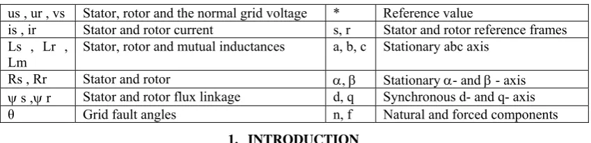
Table. 1 Nomenclature
us , ur , vs Stator, rotor and the normal grid voltage * Reference value
is , ir Stator and rotor current s, r Stator and rotor reference frames Ls , Lr ,
Lm Stator, rotor and mutual inductances a, b, c Stationary abc axis Rs , Rr Stator and rotor , Stationary - and - axis s ,r Stator and rotor flux linkage d, q Synchronous d- and q- axis
θ Grid fault angles n, f Natural and forced components
1. INTRODUCTION
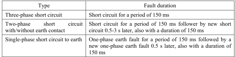
Table 2. Grid code requirements of wind farm during recurring faults
Type Fault duration
Three-phase short circuit Short circuit for a period of 150 ms Two-phase short circuit
with/without earth contact Short circuit for a period of 150 ms follower by new short circuit 0.5-3 s later, also with a duration of 150 ms Single-phase short circuit to earth One-phase earth fault for a period of 150 ms followed by a new one-phase earth fault 0.5 s later, also with a duration of 150 ms
The variable speed WTS mainly uses DFIG as a generator. The stator winding is connected directly to the grid and the rotor winding is connected by a back-to-back converter. A multi stage gear box is necessary in this drive. This WTS with DFIG has many advantages. They are of high controllability, easy to synchronize to grid, maximum power extraction and reactive power compensation by using back to back power converters of rating near to 25-30% of the generator capacity [4]. The main disadvantage is the gear box will take more time to repair, if damage occurs [5]. The DFIG is more sensitive to grid voltage disturbances and voltage dips due to grid faults [6]. This voltage dips will produce an extra stator natural flux in the stator winding. The extra flux can be controlled by conventional vector control [7], [8].This flux may introduce over current and voltage in the rotor circuit and may damage the rotor windings [9], [10]. To avoid this, rotor current is required to inject in rotor circuit. The injected current should in phase opposition to stator natural flux. So, the decay of the stator natural flux can be accelerated [11 – 13]. In general the crowbar is used to bypass the high current in the rotor circuit under grid faults [14]. The crowbar is connected under voltage dips to limit the rotor current. The crowbar is disconnected after 100 ms and rotor side convertor (RSC) is connected back to support the reactive power [15 – 17]. For a recurring fault, the stator natural flux may exist at the time of next fault. Even though the vector control is applied, the DFIG may fail to ride through the recurring grid faults [18]. This is due to large time constant of stator is around 1 to 2 s and shortest duration between two faults is about 500 ms according to grid code [19]. So, the control strategies for FRT of single grid faults are not a solution for recurring grid faults. An improved control strategy is implemented during voltage recovery after the voltage dips occur. In this control a rotor natural current is injected into the rotor circuit with rotor rotational frequency. The injected current is in phase opposition to the direction of the stator natural flux. This results the damping of stator natural flux gets accelerated [20]. In this paper an advanced controller is used for the above said improved control strategy. The conventional PI controller is replaced with fuzzy Logic Controller (FLC). By implementing FLC the transient current and voltage of rotor under recurring faults can be controlled better than conventional PI controller. Hence the electromagnetic torque fluctuations can be suppressed and the reliability of the mechanical system can be improved. The brief outline of this paper is organized as follows: Section 2 presents the vector control of DFIG WTS under normal working condition. Section 3 presents the DFIG WTS with rotor side crowbar under voltage dips. Section 4 presents the DFIG WTS under recurring grid faults when crowbar is not active and in active condition during voltage recovery. Section 5 describes the improved control strategy of DFIG WTS for recurring grid faults. Section 6 presents the implementation of advanced controller to DFIG WTS to ride through recurring grid fault is verified by simulation in MATLAB software. Section 7 contains the simulation results and the conclusions are drawn in Section 8.
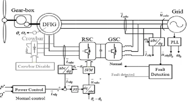
II. VECTOR CONTROL OF DFIG WTS
The vecto are prese
The rotor current in crowbar
Where
or control of D ented and discu
r side crowba n the rotor cir [20]. The dyn
DFIG WTS un ussed in sectio
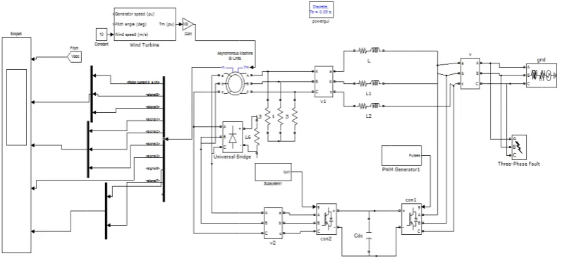
Fig.2. Matla
III. DFI ar is generally
rcuit to protec namic model o
Fig.1.Ve
nder recurring on 7.
ab/Simulation mo
IG WTS WIT y used for DF ct the convert of DFIG is rep
ector control of D
g grid faults is
odel diagram of D
TH ROTOR S FIG under gri ter circuit. Th presented by E
FIG WTS
s modeled in M
DFIG WTS with v
SIDE CROW id faults. The he fig.3 shows Eq.1 in stator α
Matlab is show
vector control
WBAR crowbar is u s the DFIG W
αβ reference f
wn in fig.2.Th
used to bypas WTS with roto
frame [21, 22]
(1)
he outputs
s high or side
Under gr magnitud The DFIG presented This sect recovery a. Case The react At t0 the crowbar recovery between In this c electroma
rid fault the cr de of the volta G WTS under d and discusse
tion explains t and the crowb e.1: Crowbar i
tion of DFIG first fault is is disabled. T
starts. The n two faults is 5 condition the agnetic torque
rowbar is trig age drop acro r recurring gri ed in section 7
Fig.4. Ma
IV. DFIG the DFIG WT bar is active d is not active d with rotor sid happen and t The vector co
ext fault happ 500 ms, the cr
DFIG may e (around 2 p.
Fig.3.DF
ggered. The vo ss the crowba id faults with 7.
atlab/Simulation
WTS UNDE TS under recu during voltage during voltage de crowbar no the crowbar i ontrol comes pens at t3, the rowbar cannot
fails to ride u) at this cond
FIG with rotor sid
oltage across ar is the produ
crowbar is mo
model diagram o
R RECURRI urring grid fau e recovery.
recovery ot active unde
s enabled. Th into the circu same action t withstand fo though the r dition may dam
de crowbar
rotor side con uct of rotor cu odeled in Mat
f DFIG WTS wit
ING GRID F ults when crow
er recurring gr he RSC is abl uit for reactiv
will takes pla r high transien recurring fau mage the mec
nverter is conn urrent and res tlab is shown i
th crowbar
FAULTS wbar is not ac
rid faults are e le to control t ve power con ace like first f nt current at th ults with crow chanical system
nected to crow sistance of the
in fig.4.The o
ctive during v
explained in F the DGIG at ntrol. At t2 th fault.If the tim he time of sec wbar alone. D
m [19, 20].
wbar. The e crowbar. utputs are
voltage
Fig.5.Response of DFIG during recurring grid faults with crowbar not active after voltage recovery
b. Case.2: Crowbar is active during voltage recovery
The reaction of DFIG with rotor side crowbar is active under recurring grid faults are explained in Fig.6 [20]. Up to t2 the operation is same as previous case. At t2 the crowbar is active again. The stator natural flux will decrease well as compared with the case 1. But still there is a disadvantage by using this control is that, large electromagnetic torque appears (around 1 p.u). This will leads to damage the gear box [20].
Fig.6.Response of DFIG during recurring grid faults with crowbar active again after voltage recovery
V. IMPROVED CONTROL STRATEGY OF A DFIG WTS FOR RECURRING GRID FAULTS The purpose of this control is to accelerate the damping of stator natural flux at the voltage recovery time. So, the electromagnetic torque can be suppressed and to improve the reliability of the mechanical system. Fig.7 (a) shows the response of DFIG with this improved control. The improved control is applied only at voltage recovery time. This will introduce a rotor natural current which is in opposite direction to stator natural flux. Due to this the damping of stator natural flux is accelerated and at same time the electromagnetic torque can be suppressed. The Fig.7 (b) shows the resultant flux during t2 and t3 when improved control is applied [20].
(a) (b)
Fig.7 DFIG during recurring grid faults with improved control: (a) response of DFIG and its stator flux and
(b) Vector diagram of rotor current and stator current flux with improved control
The RSC has to generate rotor current with two different frequencies. They are the rotor natural current and rotor forced natural current. They are represented in the Eq.2
(2) Where are stator natural and forced flux and k1 and k2 are proportional coefficients.
By Eq.2 in Eq.1 the rotor natural current and forced current will be represented in Eq.3
(3) By considering the safety limits the best accelerating effect of the RSC is represented in Eq.4 [20].
(4) Hence the rotor current vector can be expressed as
(5) The Fig.8 shows the improved control. This control accelerates the damping of stator natural flux and at the same time the electromagnetic torque will be suppressed. Hence the reliability of mechanical system is improved.
The improved control method of DFIG WTS under recurring grid faults is modeled in MATLAB is shown in fig.9.The outputs are presented and discussed in section 7.
Fig.9 Matlab/Simulation model diagram of DFIG WTS for Improved control method
VI. IMPLEMENTATION OF ADVANCED CONTROLLER TO DFIG WTS FOR RIDE THROUGH RECURRING GRID FAULTS
A new fuzzy logic control is used to implement the controller of DFIG WTS for ride through recurring grid faults. The PI controller is tuned for a specific linearized model. It may not provide required damping for all operating conditions caused by disturbances/voltage dips/faults and parameter uncertainties. This may cause severe electromagnetic torque fluctuations. Further the mechanical system of WTS may affects/damaged. To improve the mechanical system of WTS over a wide range of operating points, the use of a fuzzy controller is proposed in this paper. The fuzzy controller is used for ride through symmetrical grid faults of DFIG WTS. The fuzzy-logic based controllers have shown better performance than the conventional PI controller. Some of the advantages of fuzzy logic controller than PI controller are listed. They are, the mathematical model is not necessary to controller synthesis, it tolerates parameter imprecision or parameter variations, and allows the agreement between opposing control actions. Fuzzy logic is mostly preferred due to high precision, good response, works efficiently and perfectly. The proposed Fuzzy Logic control model is implemented to DFIG WTS in MATLAB/SIMULINK and Fuzzy Logic Toolbox [23].
The fuzzy logic controller is implemented on the DFIG WTS under recurring grid faults. The purpose is to accelerate the damping of stator natural flux at the voltage recovery time. So, the electromagnetic torque can be suppressed and to improve the reliability of the mechanical system. The controller injects the rotor natural current to accelerate the damping of the stator natural flux. Fig.10. shows the fuzzy logic control model in MATLAB/SIMLINK. The Fig.11. shows sub-circuit of implemented model. The outputs are presented and discussed in section 7.
Fig.11Sub-circuit of advanced controller to DFIG WTS
VII. SIMULATION RESULTS
Simulation is done of 1.5MW DFIG model in simulink/MATLAB. The parameters of the DFIG are shown in Appendix of this paper. The performance of DFIG under recurring grid faults for different control strategies are simulated and the results are shown in fig.12. The control strategies are as follows:
(a) Vector control (b) Crowbar active again
(c) Improved control after voltage recovery and (d) Advanced controller with FLC
The voltage dips taken in this simulation model is 80% of grid voltage for both faults and the duration between the faults is 500 ms. The faults happens at t0 = 1.5s and t3 = 2.18s respectively.
a. Vector control
The vector control method is applied at t2 = 1.67s at the time of voltage recovery. The stator natural flux is decreases slowly. For next fault at t3 it is observed that the voltage dip and stator natural flux is suppressed, but the transient currents of rotor and stator are large and the electromagnetic torque fluctuations are more. The rotor transient current under first fault is 1 pu but under second fault it reaches around 1.5 pu. The stator transient current under first fault is 2.3 pu but under second fault it reaches around 3.8 pu. The response of DFIG with vector control is shown in fig.12 (a).
b. Crowbar active again
The crowbar is active again at t2 for 250 ms duration after voltage recovery. The damping of stator natural flux is accelerated. For next fault the response of DFIG is same for transient currents and electromagnetic torque fluctuations. It is observed that a large electromagnetic torque reaches around 2 pu. This may affects the mechanical system. The response of DFIG with crowbar active again after voltage recovery is shown in fig.12(b).
c. Improved control after voltage recovery
The improved control method is applied after voltage recovery at t2. The rotor natural current is injected into the rotor circuit is given by Eq. (5). After injecting the rotor current, the transient rotor and stator currents are controlled. It is observed from the response of DFIG by improved control, the electromagnetic torque fluctuations are very small after voltage recovery. The response of DFIG with improved control after voltage recovery is shown in fig.12(c).
d. Advanced controller with FLC
The fuzzy logic controller is implemented on the DFIG WTS under recurring grid faults. The voltage dips taken in this simulation model is 50% of grid voltage. The performance of DFIG under recurring grid faults with crowbar and improved control with fuzzy logic controller is shown in fig.12 (d). It is observed that the performance of DFIG with fuzzy logic controller compared with conventional PI controller is good. The response time and accuracy of FLC is better than the PI controller. The damping of stator natural flux under voltage recovery time is accelerated and electromagnetic torque is suppressed. Which improve the reliability of the mechanical system.
(a) (b)
(b) (d)
Fig.12.Performance of DFIG under recurring grid faults (a) Vector control (b) Crowbar active again (c) Improved control after voltage
recovery and (d) Advanced controller with FLC
VIII. CONCLUSIONS
Appendix
Parameters of DFIG
Parameters Rating
Rated power 1.5 MW
Rated voltage (L-L) 670 V
Frequency 50 Hz
Stator resistance R s 2.139 mΩ
Stator inductance Ls 4.05 mH Rotor resistance R r 2.139 mΩ
Rotor inductance L r 4.09 mH Mutual inductance L m 4.00 mH
Inertia 63.87 Kg/sq.m
Friction factor 0 N-ms
Pole pairs 2
References
[1] Manaullah, Arvind Kumar Sharma, Hemant Ahuja, Arika Singh,“Performance Comparison of DFIG and SCIG based Wind Energy
Conversion Systems”, International Conference on Innovative Applications of Computational Intelligence on Power, Energy and Controls with their Impact on Humanity (CIPECH14) 28 & 29 November 2014.
[2] Peter E. Sutherland“Canadian grid codes and wind farm interconnections”, Industrial & Commercial Power Systems Technical
Conference (I&CPS), 2015 IEEE/IAS 51st.
[3] Energinet.dk,”Technical regulation 3.2.5 for wind power plants with a power output greater than 11 kW”, available on:
http://energinet.dk
[4] Hemant Ahuja, G. Bhuvaneswari, R. Balasubramanian,” Performance Comparison of DFIG and PMSG based WECS”, Renewable
Power Generation (RPG 2011), IET Conference
[5] F. Spinato, P.J. Tavner, G.J.W. van Bussel, E. Koutoulakos,” Reliability of wind turbine subassemblies”, IET Renew. Power Gener.,
2009, Vol. 3, Iss. 4, pp. 387–401
[6] J. Hu, Y. He, L. Xu, B.W. Williams, "Improved Control of DFIG Systems During Network Unbalance Using PI–R Current
Regulators," IEEE Trans. Ind. Electron, vol.56, no.2, pp.439 - 451, 2009.
[7] L. Jesus, S. Pablo, S. Xavier, M. Luis, “Dynamic behavior of the doubly fed induction generator during three-phase voltage dips”,
IEEE Trans. Energy Convers. , Vol.22, No.3, pp. 709-718, Sep 2007.
[8] X. Kong, Z. Zhang, X. Yin and M. Wen, “Study of fault current characteristics of the DFIG considering dynamic response of the
RSC”, IEEE Trans. Energy Convers., vol.29, no.2, pp. 278-287, June. 2014.
[9] J. Morren and S. W. H. de Haan, “Short-circuit current of wind turbines with doubly fed induction generator,” IEEE Trans. Energy
Convers., vol. 22, no. 1, pp. 174–180, Mar. 2007.
[10] S. Xiao, G. Yang, H. Zhou and H. Geng, “Analysis of the control limit for rotor-side converter for doubly fed induction
generator-based wind energy conversion system under various voltage dips”, IET Ren. Power Gen., vol.7, iss. 1, pp. 71-81, 2013
[11] D. Xiang, L. Ran, P. J. Tavner, and S. Yang, “Control of a doubly-fed induction generator in a wind turbine during grid fault
ride-through”, IEEE Trans. Energy Convers., vol. 21, no. 3, pp. 652-662, Sep. 2006.
[12] L. Zhou, J. Liu and S. Zhou, “Improved Demagnetization Control of a Doubly-fed Induction Generator under Balanced Grid Fault”,
IEEE Trans. Power Electron., early access, 2014.
[13] S. Hu, X. Lin, Y. Kong and X. Zhou, “An improved low-voltage ride through control strategy of doubly fed induction generator during
grid faults”, IEEE Trans. Power Electron., vol 26, no.12, pp. 3653-3665, Dec. 2011.
[14] J. Morren, and S. W. H. de Haan, “Ride Through of Wind Turbines with Doubly-Fed Induction Generator during a Voltage Dip”,
IEEE Trans. on Energy Convers., Vol. 20, No.2, pp. 435-441, Jun. 2005.
[15] J. Vidal, G. Abad, J. Arza and S. Aurtenechea, “Single-phase DC crowbar topologies for low voltage ride through fulfillment of
high-power doubly fed induction generator-based wind turbines”, IEEE Trans. on Energy Convers., Vol. 28, No.3, pp. 435-441, 2013.
[16] M. Mohseni and S. M. Islam, “Transient control of DFIG-based wind power plants in compliance with the Australian grid code”, IEEE
Trans. Power Electron., vol. 27, no. 6, pp.118-130, June. 2012.
[17] D. Zhou, F. Blaabjerg, T. Franke, M Tonnes and M. Lau, “Reduced Cost of Reactive Power in Doubly Fed Induction Generator Wind
Turbine System with Optimized Grid Filter”, IEEE Trans. Power Electron., early access, 2014.
[18] A. H. Kasem, E. F. EI-Saaday, H. H. EI-Tamaly and M. A. A. Wahab, “An improved fault ride-through strategy for doubly fed
induction generator-based wind turbines,” IET Renew. Power Gen., vol.2, no. 4, pp 201 – 214, 2008.
[19] W. Chen, F. Blaabjerg, N. Zhu, M. Chen and D. Xu, “Doubly Fed Induction Generator wind turbine system subject to recurring grid
faults” in Proc. IEEE Applied Power Electronics Conference and Exposition (APEC), pp. 3097 – 3104, 2014.
[20] Wenjie Chen, Dehong Xu, Nan Zhu, Min Chen, Frede Blaabjerg, “Control of Doubly Fed Induction Generator to Ride Through
Recurring Grid Faults” in IEEE Transactions on Power Electronics ( Volume: 31, Issue: 7, July 2016 )
[21] M. Mohseni, S.M. Islam and M.A.S. Masoum, “Impacts of symmetrical and asymmetrical voltage sags on DFIG-based wind turbines
considering phase-angle jump, voltage recovery, and sag parameters”, IEEE Trans. Power Electron., vol. 26, no.5, pp. 1587-1598, May 2011.
[22] M. Mohseni, S.M. Islam and M.A.S. Masoum, “Enhanced Hysteresis-Based Current Regulators in Vector Control of DFIG Wind
Turbines”, IEEE Trans. Power Electron., vol. 26, no.5, pp. 1587-1598, May 2011.