SYNTHESIS OF PARALLEL
MECHANISM BASED ROBOT
MANIPULATORS FROM STRUCTURAL
POINT OF VIEW
DR. JAGDISH M. PRAJAPATI
Department of Mechanical Engineering Maharaja Sayajirao University of Baroda, Vadodara
Vadodara, Gujarat, India
Abstract:
Because of their potential merits, the parallel mechanisms are more popular than serial mechanisms based robot manipulators in specific applications. One of the ways of classifying the parallel manipulators is according to their platform types and connection between them. Methods for designing different types of parallel manipulators with one or more platforms are presented. The classification of parallel mechanism based manipulators and synthesis of them from structural point of view are presented in this paper. The step by step procedure is presented with help of examples.
Keywords: Synthesis; Parallel Mechanism; Manipulator.
1.Introduction
Structural synthesis is one of the basic questions to be answered in designing a robot manipulator. The kinematic pairs will be over loaded, if this problem were not focused. If designing of robot manipulators is done from structural point of view it is possible to refine and correct the robot structure.
Davis and Crossley [1] used Frank’s condensed notations for structural analysis of planer kinematic chains. Dobrianskyi and Freudenstein [2] used the graph theory for structural synthesis of mechanisms. Sohn and Freudestein [3] used dual graph concept and generated with up to 11 links and 2 degree of freedom. The method presented by Rao and Deshmukh [4] is based on the concept of loop formation, which eliminates the test requirements for isomorphism. A computer aided method for generating planer kinematic chains was introduced by Sohn [5]. Tischler and coworkers [6] presented the method to create the chains using a test for avoiding isomorphism.
In the method, presented here, for given set of parameters of synthesis, first, simple structural graphs are identified. Then a manipulator is formed by adding number of required actuators to the group. In addition to this, other requirements related to manipulator design like geometry and kinematics is also taken into account from structural point of view.
2. General Structural Formulation of Parallel Manipulators
The parameters connected to synthesis of the parallel manipulators are number of branches, platforms and the sum of mobility of kinematic pairs. Hence, the structural formula for a parallel manipulator is a function of above said parameters. A parallel manipulator can be constituted only when a platform is connected by at least three legs and/or branches. So, a platform is a link having pairs, where, 3.
In a parallel manipulator a mobile platform is connected to a fixed link by serial kinematic chains. Generally, these kinematic chains are referred as legs. It is possible to have a parallel manipulator having more than one mobile platform, then these mobile platforms are connected to each other by means of serial kinematic chains – branches.
Consider a general parallel manipulator with following notations: = the number of mobile platforms
= total number of joints on the platform = total number of branches
= total number of legs
(1) So, the total number of moving links, is given by
(2)
with assumption that each leg and branch of the manipulator is made up of only one link. But in actual practice it may possible that, a leg or branch may consist of more than one link. Considering the general case, let a leg is having ′ number of additional links. So, the total number of moving links of a leg are 1 ′. Also, because of these, there will be ′ number of additional joints on the leg to connect the additional links such that ′ ′. And as a result of same treatment for a branch will give ′ ′, where, ′ and ′ are the number
of additional joints and links on a branch. So the next form of the “Eq. (2)” will be
∑ ′,
∑′, (3)
Similarly, considering that each leg or branch in a structural group consists only one link. Hence, each branch constitutes two joints on different mobile platforms and each leg forms two joints, one on a mobile platform and other on a fixed link. So, in the structural group total numbers of joints are given by
(4)
Again considering the general case, a leg or a branch is made up of more than one link, the “Eq. (4)” is extended as
∑ ′, ∑ ′,
(5)
In a closed kinematic chain, the numbers of independent loops are given by
(6)
Involvement of “Eq. (3)” & “Eq. (5)” in “Eq. (6)” will give the formula to know number of independent loops as:
(7)
According to definition a branch connects two mobile platforms while a leg connects a mobile platform and a fixed link. So, the total number of joints on the mobile platforms in a general parallel manipulator is given as:
2 (8)
Using “Eq. (1)” in “Eq. (8)”
(9)
Substitution of “Eq. (9)” into “Eq. (7)” gives
(10)
The degree of freedom of a spatial mechanism is given as
∑ (11)
Where, is the degree of freedom of the mechanism, is the total number of joints in the mechanism, is the mobility of the ith joint, is the number of independent closed loops and is the degree of freedom of an unconstrained rigid body moving in the work space of the mechanism. Putting “Eq. (7)” into “Eq. (11)” to obtain
∑ ! (12)
Similarly, involvement of “Eq. (10)” in “Eq. (11)” will give
∑ ! (13)
Consideration of degree of freedom to be zero in “Eq. (12)” and “Eq. (13)” will give equation for structural groups
∑ ! (14)
∑ ! (15)
“Eq. (14)” and “Eq. (15)” represent structural groups of parallel manipulator having minimum one mobile platform.
3. Structural Synthesis of Parallel Manipulators
Selection of right structural group and addition of required number of actuators will give a parallel manipulator with required degree of freedom. The sum of mobility of all joints in the structural group is given by " ∑ . So, “Eq. (15)” can be rewritten as
" ! (16)
In this method to initiate, we need to decide the number of mobile platforms and total number of joints on platforms . The first step, for structural synthesis by this method is to find the number of possible different structural groups using these parameters. The following conditions are required to be justified for formation of a structural group with mobile platforms, branches and legs.
(2) Two mobile platforms should be connected at least by one branch.
(3) A mobile platform and the fixed link should be connected at least by two legs.
The minimum number of branches required to satisfy the 2nd condition minimally are 1 Due to this configuration, the total numbers of unconnected joints left on the mobile platform are: 2 1!. So, The first condition will force us to have total number of legs 2 1!.
Thus in this situation, we will have a structural with maximum total number of branches and legs, given as: $% , , $%
& $% 1! 2 1!!
& $% 1 (17)
To minimally satisfy the 3rd condition 2.
In this situation the total number of joints on the platforms left to connect the branches are 2. So the total number of branches will be 2!/2 0.5 1.
In this case we can say that the minimum number of branches and legs that can be used in a structural group is given by , $% , 0.5 1 2
1 0.5 (18)
In the situations, the total number of joints being an odd number, then the value of is rounded up. “Eq. (17)” and “Eq. (18)” collectively can establish the following relation.
1 0.5 * * 1 (19)
For given number of mobile platforms , we can say from “Eq. (15)” that the number of different structural groups, depends on the number of different values those can be taken by . As is a natural number existing in a closed interval +, $%,, the number of different values that may take is given by $% 1; that is;
- 1 0.5 (20)
Hence - is the number of structural groups possible for given & . If value of is an odd number the value of - is rounded down.
Problem: Synthesize a six degree of freedom spatial parallel manipulator from structural point of view.
(1) Decide the number of mobile platforms and the total number of joints on the platforms . Let us take two hexagonal platforms. So, 2, 6 6 12, 6, 6.
(2) Decide the number of different structural groups - with help of “Eq. (20)”. - 1 0.5 5 (3) Decide the total number of connections (i. e. the sum of total number of branches and total number of
legs) by “Eq. (19)”. From “Eq. (19)” possible values of are between 1 0.5 & 1 . & 7 * * 11
(4) Calculate the number of branches with “Eq. (9)”. For 7, we find 12 7, hence 5
(5) Calculate the number of legs from “Eq. (1)” , & 7 5 , & 2
(6) Calculate the sum of mobility of all joints with “Eq. (16)”.
Sum of mobility of all joints " !, & " 6 7 2! 30
Since, we have total number of seven branches and legs so it will be desirable to place four joints on each branch and five joints on each leg.
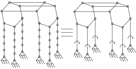
(7) The arrangement of 7 is shown in Fig. 1.
Fig. 1. Structural synthesis for 7
(8) Find out the places where to add actuators. We need to place same number of actuators as the number of degree of freedom. One may place the actuators on the legs or branches and also more than one actuator may be placed on the same leg or branch. Putting one actuator on each leg and four actuators on four branches.
Fig. 2. Structural synthesis for 8
In same way we can proceed for different values of up to 11. And we find different configurations. But it is desirable to put all actuators resting on the frame. This will reduce the inertia and required force/torque in manipulation of manipulator. This results in that no actuator is placed in any branch, but all actuators are placed in legs and in each leg only one actuator is placed.
For this criteria in consideration, take number of legs is equal to the degree of freedom . 2nd step is not required to be followed and numbers of branches are computed using “Eq. (8)”. In 3rd step, can be known from “Eq. (1)”. The remaining steps are as they are to be followed. Only one such group exists for a given set of and 2.
Taking the same example, with this criterion. Here, 2, 12 and 6. Use of “Eq. (8)” gives 3 and “Eq. (1)” gives 9. And sum of mobility 42. Here total number of branches and legs are nine. As total number of joints are 42, let us put six joints on each leg and two joints on each branch.
Fig. 3. Structural synthesis for 9
4. Structural Classifications
• Number of mobile platforms decide the class of structural group.
• Type of a structural group is expressed as a set of numbers, such that each number in the set is the number of joints on one of the mobile platforms.
• Number of branches identifies the kind of a structural group. • Order of the structural group is nothing but number of legs it having.
5. Geometrical (Structural) Synthesis
5.1. Simple branch and leg configurations
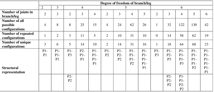
Table 1. Possible configurations.
To understand, consider 3rd column, a chain having 3 degree of freedom. So, possible number of joints are P1 – P1 – P1 (last raw). There are 8 possible configurations: P-P-P; P-P-R; P-R-P; P; R-R-R; R-R-P; R-P-R; P-R-R. But, P-P-R & R-P-P and R-R-P & P-R-R are the same from the structural point of view (Raw 5). So, we can have 8 - 2 = 6 unique configurations (Raw 6).
5.2. Complex branch and leg configurations
This paper presents synthesis of parallel manipulators from structural point of view having serial branch or leg structures. However a leg or a branch can also be a combination of serial kinematic chains and simple structural groups. A new methodology should be search out for this kind of situations.
5.3. Modular parallel manipulator.
With use of complex structural groups, modular parallel manipulators can be constructed. Many times it is possible that a complex structural group can be made by combining two or more simple structural groups. So, it is important to identify such complex structural groups.
6. Conclusion
This paper presents a structural formula of parallel manipulators with moving platform/s. with simple structural groups, how the structures of parallel manipulators are synthesis is explained. A classification for parallel manipulators based on the number of mobile platforms, number of joints on the mobile platforms, number of legs & branches and types of kinematic pairs is given.
References
[1] Davies, T. H.; Crossley, F. R. E. (1966) Structural analysis of plane linkages by Franke’s condensed notation, J. Mech. 1 pp. 171 -
183.
[2] Dobrjanskyi, L.; Freudenstein, P. (1967) Some applications of graph theory to the structural analysis of mechanisms, Trans. ASME J.
Eng. Ind. pp.153 – 158.
[3] Hwang, W. M.; Hwang, Y. W. (1992) Computer-aided structural synthesis of planer kinematic chains with simple joints, Mech. Mach.
Theory 27 (2). pp. 189 – 199.
[4] Rao, A. C.; Deshmukh, P. B. (2001) Computer aided structural synthesis of planer kinematic chains obviating the test for
isomorphism,Mech. Mach. Theory 36. pp. 489 – 506.
[5] Sohn, W. J.; Freudenstein, F. (1986) An application of dual graphs to the automatic generation of kinematic structures of mechanisms,
Trans. ASME 108 pp. 392 – 398.
[6] Tischler, C. R.; Samuel, A. E.; Hunt, K. H. (1995) Kinematic chains for robot hands – I orderly number synthesis, Mech. Mach.
Theory 30. pp. 1193 – 1215.
Degree of freedom of branch/leg
2 3 4 5 6
Number of joints in
branch/leg 2 3 2 3 4 2 3 4 5 2 3 4 5 6
Number of all possible configurations
4 8 8 25 15 4 24 62 26 1 32 122 130 42
Number of repeated
configurations 1 2 3 11 5 2 10 31 10 0 14 58 62 19
Number of unique
configurations 3 6 5 14 10 2 14 31 16 1 18 64 68 23