FACE COMPONENT BASED
REAL-TIME PERSONAL VERIFICATION
SYSTEM
CHAI WUH SHING1, BAKHTIAR A. ROSDI2, SHAHREL A. SUANDI3
Intelligent Biometric Group, School of Electrical & Electronic Engineering, Engineering Campus, Universiti Sains Malaysia, 14300 Nibong Tebal,
Seberang Perai Selatan, Pulau Pinang, Malaysia.
1[email protected] 2[email protected] 3[email protected]
Abstract:
This paper describes a technique to verify an identity using both eyes and mouth, instead of entire face area (holistic method). The algorithm employs template matching as the principal technique in verification engine. Each of these components is utilized as an independent component in the verification engine. As a result, the system can perform well even though the mouth is covered or temporal occlusion occurred. The system starts by detecting the face, eyes and mouth. It performs the verification within 15 degrees from frontal pose in real-time. The proposed method does not require any manual initialization and parameter tuning.
Keywords: Face component; verification system.
1. Introduction
Every human face is a unique feature and it is a pattern of infinite variety. The combinations of the facial components allow us to differentiate a person’s identity. Thus, the face plays an important role in the recognition process. Face recognition is applicable in many scopes. Furthermore, it can be categorized into face verification, face identification, face classification and so on. The most useful practical applications such as entrance security, crowd surveillance, video content indexing, personal identification, bankcard identification, access control and so on. A facial verification system is a computer application for automatically verifying a person from a static digital image or video source. One of the methods is by comparing the desired facial components from the input image and a facial database. It is normally used in security systems and can be combined with other biometrics such as eye iris or fingerprint verification systems. This non-intrusive person authentication system makes it an important advantage over other biometric technologies. Generally, face recognition is performed by using two approaches. The first approach is component-based which uses the geometric relationship among the facial components like mouth, nose, and eyes (Brunelli and Poggio, 1993); (Song et al., 2004). The second approach is appearance-based which utilizes entire face (Beymer, 1994); (Li et al., 2004); ( Georghiades et al., 2001).
For face and facial components detection, Erukhimov and Lee (2008) have built a general framework for detecting a set of individual facial components such as eyes, nose and lips using a bottom up approach. A joint model of discriminative and generative learners is employed providing unprecedented results in terms of both detection rate and false positives rate. An Adaboost cascade learner is used to find candidates for facial components and a graphical model selects the most likely combination of features based on their individual likelihoods as well as relative positions and infers the missing components. In Mu et al. (2001), the system uses a template matching approach along with a training algorithm for tuning the performance of the system to solve two types of problems simultaneously: 1. Correct classification experiments: correctly recognize and identify individuals who are in the database and 2. False positive experiments: reject individuals who are not part of the database. Experimental results given which indicate that this training method is capable of consistently producing high correct classification rates and low false positive rates.
compared to geometrical matching (90% recognition rate) and was also easier to be implemented. Since the principal components analysis (also known as eigenfaces or eigenfeatures) are linear combinations of the templates in the database, the technique cannot achieve better results than correlation (Brunelli and Poggio, 1993), but it may be less computationally expensive.
2. Face and Facial Components Detection
In order to verify ones identity through multiple facial components, we need to locate the region of face, right eye, left eye and mouth. This step has been performed by EMoTracker (Suandi et al., 2004). EMoTracker will first locate the face region, then proceed with the eyes and mouth detection within the face region. This application will provide all the region of interest. EMoTracker extracts the human face from an image using color information. The tracker locates the skin like regions by performing color segmentation. For human skin color segmentation, it is sufficient to consider rg color space as discriminating color information. Using the rg color space as in Equation (1), the parameters for each domain have been fixed as follows: 0.37 ≤ r ≤ 0.47 and 0.28 ≤ g ≤ 0.35 (Suandi et al., 2004).
,
B
G
R
R
r
+
+
=
B
G
R
G
g
+
+
=
(1)Generally, approach using human skin-color distribution is preferred due to its’ simplicity in computation and robustness towards complex scene. Unfortunately, there is a drawback behind this approach. When skin color regions such as faces or hands are imaged under natural environments, their color appearance is frequently affected by variations in illumination intensity and chromaticity. For skin color based detection and tracking, changing intensity is often dismissed either with the use of normalized, intensity invariant color coordinates or by additionally modeling possible skin intensities (Martinkauppi et al., 2005). In our work, we noticed that EMoTracker suffers from illumination variation. To overcome this problem, we decided to use Viola and Jones (2001) face detector to perform face detection. Their algorithm is based on asymmetric AdaBoost and cascade detector Cascade. It provides extremely fast detection with high detection rates, very low false positive rates. The face detection system can process 15 frames per second achieving over 90% detection, and a false positive rate of 1 in a 1,000,000.
Fig. 1. Performance of the EMoTracker with different approaches: (a)Input image, (b)Binary image, (c)Output using skin color detection,
(d)Output using Viola and Jones (2001) face detector.
Fig. 2. Performance of the EMoTracker with different approaches: (a)Input image, (b)Binary image, (c)Output using skin color detection,
(d)Output using Viola and Jones (2001) face detector.
Fig. 3. Performance of the EMoTracker with different approaches: (a)Input image, (b)Binary image, (c)Output using skin color detection,
(d)Output using Viola and Jones (2001) face detector.
For example in Fig. 1, Fig. 2 and Fig. 3, (a) are the input images, (b) are the binary images, whereby black color pixels are the skin color pixels of the input images, (c) are the output of EMoTracker with skin color detection approach, (d) are the output of EMoTracker with Viola and Jones (2001) face detector. For Fig. 1(b), the system only defines the left side of the face as the face region. For Fig. 2(b), the skin color scarf has confuses the system. For Fig. 3(b), the system even cannot find the skin color region of the face. All of these conditions have made the system performs in an unusual way, which subsequently makes the detection rate for facial components drop significantly. On the other hand, Fig. 1(d), Fig. 2(d) and Fig. 3(d) show that the Viola and Jones (2001) face detector performs well under different illumination conditions.
3. Verification Engine
The proposed method utilizes template matching as its principal technique in verification engine. Template matching is a technique in digital image processing for finding small parts of an image which match a template image. This technique can be performed on grayscale images. The normalized correlation coefficient ρX,Y
between two random variables X and Y with expected values μX and μy and standard deviations σX and σYcan be
computed using Equation (2):
Y X Y X Y X Y X,
σ
σ
)]
μ
-)(Y
μ
-E[(X
σ
σ
Y
X,
cov
ρ
=
(
)
=
(2)where, E is the expected value operator and cov means covariance. The range of the normalized correlation coefficient is as follow: -1 ≤ρX,Y≤ 1.
In this research, variables X are the input values of the selected component after normalization. In other words, the input value is a 10 x10 array due to the normalization of the component into 10 x10 pixels template. On the other hand, variables Y are the corresponding database values. These three facial components (right eye, left eye and mouth) have their own correlation value. Table 1 shows all possible outcomes of the system; 1 and 0, where 1 is correctly verified and 0 means rejected. 1 and 0 are defined using Equation (3).
<
≥
=
.
ρ
,
0
,
ρ
,
1
Y X, Y X,th
th
Vi
(3)where Viis the verification results (1 or 0), th is the threshold value and i is the index for ’left eye’, ’right eye’,
and ’mouth’. As shown in Table 1, if more than two 1’s are yielded, the identity is verified correctly, or otherwise rejected.
Table 1. The list of all possible outcomes.
Vle Vre Vm Verification Output
0 0 0
0 0 1
0 1 0
0 1 1 ✓
1 0 0
1 0 1 ✓
1 1 0 ✓
1 1 1 ✓
4. Thresholding (False Acceptance / False Rejection Rates)
In our work scores are used to express the similarity between a pattern and a biometric template. The higher the
score is, the higher is the similarity between them. Access to the verification system is granted only, if the score for the person that the pattern is verified against is higher than a certain threshold.
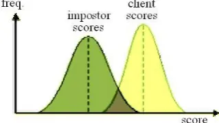
In theory, client scores (scores of patterns from persons known by the system) should always be higher than the scores of impostors. If this would be true, a single threshold, that separates the two groups of scores, could be used to differ between clients and impostors. Due to several reasons, this assumption isn’t true for real world biometric systems. In some cases impostor patterns generate scores that are higher than the scores of some client patterns. For that reason (it is a fact), that however the classification threshold is chosen, some classification errors occur. Basically there are two types of errors: the false acceptance rate (FAR) and the false rejection rate (FRR). A FAR is the rate when a non-matching pair of biometric data is wrongly accepted as a match by the system. A FRR is the rate when a matching pair of biometric data is wrongly rejected by the system. The choice of the threshold value becomes a problem if the distributions of the client and the impostor scores overlap, as shown in Fig. 4. In Fig. 5, the corresponding false acceptance and false rejection rates are displayed.
Fig. 5.
Illustration of false acceptance, false rejection and equal error rates (SYRIS Technology Corp., 2004).
Fig. 6.
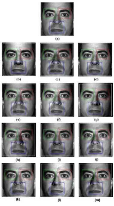
The labeled face images for subject yaleB08 with different single light source direction: (a) A+00E+00(reference image), (b) A+00E+20, (c) A+00E-20, (d) A+05E+10, (e) A+05E-10,
(f) A+10E+00, (g) A+20E+10, (h) A+20E-10, (i) A-05E+10, (j) A-05E-10, (k) A-10E+00, (l) A-20E+10, (m) A-20E-10.
In a biometric verification system, the relative false acceptance and false rejection rates can be set by choosing a particular operating point. Very low (close to zero) error rates for both errors (FAR and FRR) at the same time are not possible. By setting a high threshold, the FAR error can be close to zero, and similarly by setting a significantly low threshold, the FRR rate can be close to zero. A meaningful operating point for the threshold is decided based on the application requirements, and the FAR versus FRR error rates at that operating point may be quite different. To provide high security, biometric systems operate at a low FAR instead of the commonly recommended equal error rate (EER) operating point where FAR = FRR.
In this project, the proposed method also aims to deal with different illumination conditions, so we choose to use Yale Face Database B (SYRIS Technology Corp., 2004) as our face database to determine FAR, FRR, EER and suitable threshold for each region of interest (ROI). 130 images of 10 subjects from the Yale Face Database B have been used for this research purpose. All images are in the frontal pose; 10 of them are used as reference images and the remaining 120 images are the test images deal with the different azimuth and elevation of the single light source direction. Fig. 6 shows the labeled face images for subject yaleB08 with different single light source direction.
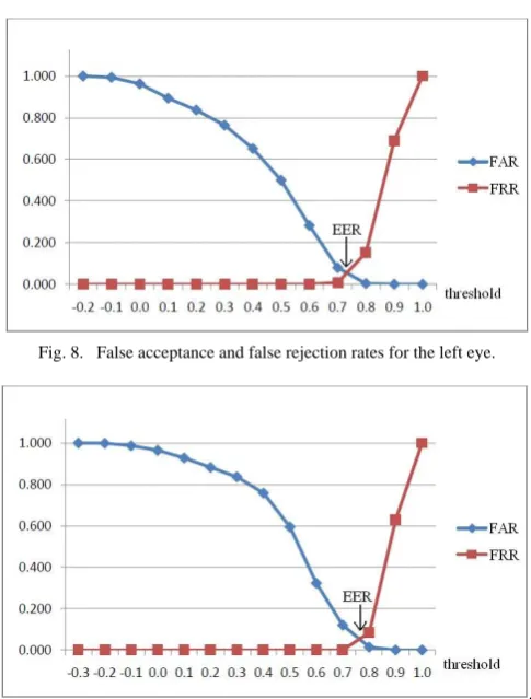
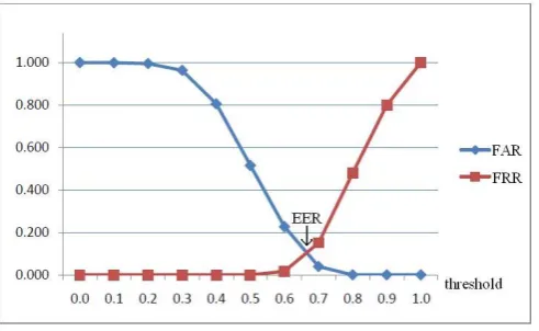
Fig. 7 ~ Fig. 10 show the FAR and FRR for a varying threshold for face and the three facial components, left eye, right eye and mouth respectively. From FAR and FRR, we easily obtained EER, the rate at which both acceptance and rejection errors are equal. The lower the equal error rate value is, the higher the
Fig. 7.
False acceptance and false rejection rates for the face.
Fig. 8.
False acceptance and false rejection rates for the left eye.
accuracy of the biometric system. From Table 2, the EER for facial components are lower than face, this is one of the benefits for applying component based method in face verification system. We then obtain the threshold for each of ROI from the point of EER, as shown in the Table 2.
Table 2. The EER and threshold for each ROI.
ROI EER Threshold
Face 0.11 0.78
Left Eye 0.06 0.74
Right Eye 0.06 0.77
Mouth 0.10 0.67
As described in the preceding section, if the threshold is reduced, there will be less false non-matches but more false accepts. Correspondingly, a higher threshold will reduce biometric systems operate at a low FAR (therefore, high FRR) instead of the commonly recommended EER operating point, we increase the threshold value for each ROI to 0.80. Table 3 shows the FAR for each ROI when threshold = 0.80.
Table 3. The FAR for each ROI when threshold = 0.80.
ROI FAR Face 0.03 Left Eye 0.00
Right Eye 0.01
Mouth 0.00
5. Experiment and Results
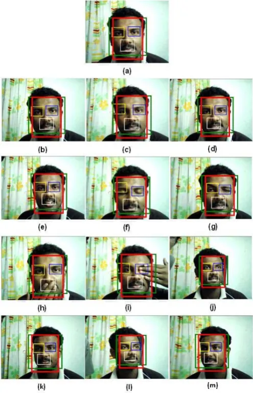
There are 130 color images from self created face database have been used to evaluate the performance of the proposed algorithm. The size of each image is 320 x 240 pixels and consists of 10 subjects. The database has 13 categories for each 10 subjects; 5 different poses, 6 different facial expressions and 2 different occlusions. These categories are shown in Table 4 and the example images for each category are shown in Fig. 11.The size of the face database is not large but the variety of faces, subjects and categories are more than adequate to test the robustness of the system.
5.1. Component-based Method
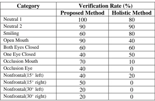
From Table 5, we can say that the proposed method is able to handle the neutral 1, neutral 2 and open mouth categories very well. It is hard for the system to verify a person in categories of nonfrontal 30 degree to left and to right. The system performs moderately for the remaining categories.
Fig. 10.
False acceptance and false rejection rates for the mouth.
5.2. Holistic Face Method
From Table 5, we can say that holistic face method can handle the neutral 1, neutral 2 and smiling categories very well. Unfortunately, it is hard for the system to verify a person in the categories of occlusions and non-frontal poses. The system performs moderately for the remaining categories.
Table 4. Categories of self-created database.
5 Different Poses: 6 Different Facial Expressions: 2 Different Occlusions: Frontal pose
Nonfrontal pose (15 degree to left) Nonfrontal pose (15 degree to right) Nonfrontal pose (30 degree to left) Nonfrontal pose (30 degree to right)
Neutral 1 Neutral 2 Smiling Open mouth Both eyes closed One eye closed
Occlusion eye Occlusion mouth
5.3. Comparison between Component based Method and Holistic Face Method
Proposed method achieves higher verification rate in most of the categories except smiling and one eye closed categories. For smiling and one eye closed cases, one of the reasons for having better results using holistic method is the poor facial components detection when using component based method. Examples of failed facial component detection are shown in Fig. 11(c), Fig. 11(f) and Fig. 11(i).
Fig. 11.
Processed images for one of the subjects: (a) Reference image, (b) Neutral 1, (c) Neutral 2, (d) Smiling, (e) Open mouth, (f) Both eyes closed, (g) One eye closed, (h) Occlusion mouth,
(i) Occlusion eye, (j) Nonfrontal(15°left), (k) Nonfrontal(15°right), (l) Nonfrontal(30°left),
Table 5. Successful personal identity verification rate using proposed method and holistic method.
Category Verification Rate (%)
Proposed Method Holistic Method
Neutral 1 100 80
Neutral 2 90 90
Smiling 60 80
Open Mouth 90 40
Both Eyes Closed 60 60
One Eye Closed 40 50
Occlusion Mouth 70 10
Occlusion Eye 40 0
Nonfrontal(15°left) 40 20
Nonfrontal(15°right) 50 0
Nonfrontal(30°left) 20 0
Nonfrontal(30°right) 20 0
As expected, the effect was the greatest in the cases of facial images that have partial occlusions. The performance of this proposed method has been proven better than holistic face method by testing with the same face database. Using Equation (4), where
α
is the improved percentage, Pavg and Havg are the averageverification rate for proposed method and holistic method, the component-based method outperforms the holistic method by 61.90%.
%
(%)
H
(%)
H
(%)
P
α
avg avg avg100
x
−
=
(4)
6. Conclusion
The proposed method is an unconstrained identity verification system which is simple, fast and reliable. We have introduced a method to verify a person using facial components and identified the threshold to be 0.80. The system need only one frontal pose facial image to be enrolled as the reference image. Personal identity verification using template matching can be improved by using component-based method as discussed. Based on our experimental results, our approach shows to be more superior due to component based technique only relies on each facial component’s appearance independently, rather than taking the entire face area, which is more prone to luminance conditions. In the future, this proposed algorithm will be tested with a larger face database and additional images with different illuminations. This proposed method will be compared with other famous methods such as eigenface, neural networks, support vector machine and fisherface.
7. Acknowledgement
This work is partially supported by Universiti Sains Malaysia (USM) Postgraduate Incentive Grant (1001/PELECT/801023) and Malaysia Ministry of Finance University-Cradle Investment Programme (UCIP) project no. P1040003.
References
[1] Suandi, S. A.; Enokida, S.; Ejima, T. (2004): EMoTracker: Eyes and mouth tracker based on energy minimization criterion, 4th Indian Conference on Computer Vision, Graphics and Image Processing (ICVGIP04), pp. 269-274.
[2] Brunelli, R.; Poggio, T. (1993): Face recognition: Features versus templates, IEEE Transactions on Pattern Analysis and Machine Intelligence, 15(10) pp. 1042–1052.
[3] Song, Y.; K. He; J. Zhou; Z. Liu; K. Li. (2004): Multi-resolution feature extraction in human face, Proceedings of International Conference on Information Acquisition, pp. 417-421.
[4] Beymer, D.J., (1994): Face recognition under varying pose, Proceedings of the IEEE Conference on Computer Vision and Pattern Recognition, pp. 756–761.
[5] Li, C.M.; Y.S. Li; Q.D. Zhuang; Z.Z. Xiao. (2004): The face localization and regional features extraction, Proceedings of the 3rd
International Conference on Machine Learning and Cybernetics, pp. 26–29.
[6] Martinkauppi, B.; Soriano, M.; Pietikinen, M.. (2005): Comparison of skin color detection and tracking methods under varying illumination, Journal of Electronic Imaging, Vol. 14(4), pp. 14-19.
[7] Viola, P.; Jones, M. (2001): Fast and robust classification using asymmetric adaboost and a detector cascade, Advances in Neural Information Processing System 14, MIT Press., pp. 1311-1318.
[8] Bichsel, M. (1991): Strategies of robust object recognition for identification of human faces, Ph.D. thesis, Eidgenossischen Technischen Hochschule, Zurich.
[9] Chai, T.Y.; Rizon, M.; Woo, S.S.; Tan, C.S. (2009): Facial features for template matching based face recognition, American Journal of Applied Sciences, 6(11), pp. 1897–1901.
[10]Erukhimov, V.; K.C. Lee. (2008): A bottom-up framework for robust facial feature detection, Proceedings of the 8th IEEE International
Conference on Automatic Face and Gesture Recognition, pp. 1.
[11]Mu, X.; Artiklar, M.; Hassoun, M. H.; P. Watta. (2001): Training algorithms for robust face recognition using a template matching approach, Proceedings of International Joint Conference on Neural Networks (IJCNN ’01), 4, pp. 2877-2882.
[12]Georghiades, A.S.; Belhumeur, P.N.; Kriegman, D.J. (2001): From Few to Many: Illumination Cone Models for Face Recognition under Variable Lighting and Pose, IEEE Transactions on Pattern Analysis and Machine Intelligence, 23(6), pp. 643-660.