OPTIMIZATION OF
SHELL-THICKNESS IN MULTILAYER
PRESSURE VESSEL AND STUDY ON
EFFECT OF NUMBER OF SHELLS ON
MAXIMUM HOOP STRESS
Niranjan Kumar
Jadavpur University, Department of Mechanical Engg., City-Kolkata, State-West Bengal, ZIP/Zone-700032, Country-India
Dulal Krishna Mandal
Jadavpur University, Department of Mechanical Engg., City-Kolkata, State-West Bengal, ZIP/Zone-700032, Country-India
Samar Chandra Mondal
Jadavpur University, Department of Mechanical Engg., City-Kolkata, State-West Bengal, ZIP/Zone-700032, Country-India
Sanjib Kumar Acharyya
Jadavpur University, Department of Mechanical Engg., City-Kolkata, State-West Bengal, ZIP/Zone-700032, Country-India
Abstract:
Multilayer pressure vessel is designed to work under high pressure condition. In this paper, optimization of thickness of each layer in multilayer vessel is carried out by Genetic Algorithm and then stress distribution is analyzed under optimum shrink-fit condition. The fatigue life is calculated for shrink-fit multilayer vessel. Thickness of each vessel is considered as design variable and objective function is maximum hoop stress through-out the thickness at the given working pressure. Multilayer vessel is assumed to be constructed by insertion of different vessels with zero interference and zero clearance such that interface pressure at the mating surfaces is equal to the pressure generated at the same surface due to interference fit. The mathematical model is derived from basic governing equation of thick cylinder. The appropriate boundary conditions are applied to each successive layer. Effect of number of shells on the maximum value of hoop stress is analyzed. Apart from this, effect of overall thickness of pressure vessel on the effectiveness of multi-layering is brought into focus. Stress distribution and fatigue life for the obtained thickness of each vessel from Genetic Algorithm is nearer to that obtained from Lagrange’s multiplier method.
Keywords: Optimization; Multi-layer vessel; Autofrettaged vessel; Shell thickness; Genetic Algorithm; Fatigue Life; FE Analysis.
1. Introduction
Effect of autofrettage has been discussed by X. Huang and T. Moan [Huang and Moan, (2009)]. They analyzed elastic-plastic autofrettage process considering Bauschinger effect. X. P Huang and W.C. Cui [Huang and Cui, (2006)] worked together and discussed the effect of Bauschinger effect and yield criterion on autofrettage. But as far as multilayer vessel is concerned, Bauschinger effect is no more valid, since thickness of each layer reduces [Hill, (1998)].
Multi-layering of shells is another effective method of reducing hoop stress by introduction of shrink-fit residual stress. In earlier time, multilayer of pressure vessels was done by helical winding of roll strip on a cylindrical portion formed by a pipe. But now a day, multilayer vessels are designed by insertion of different cylindrical vessel by means of interference fit. Construction of multilayered vessel is discussed in [Fryer and Harvey, (1997)].
This analysis is based on the fact that when working pressure is zero then interface pressure at the mating surfaces is equal to the pressure generated at the same surfaces due to interference-fit. Amount of interference is given by H.L.Cox [Brownell and Young, (2009)]. As the working pressure is increased, interface pressure is the combined effect of working stress and shrink-fit residual stress. In this way, interface pressure is generated at all the mating surfaces. Then stress-calculation of each layer is done from Lame’s relationship of thick cylinder subjected to pressure at inner and outer surfaces (interface pressure for all vessels except the outer vessel). The mathematical formulations were first presented by H.L.Cox in 1936. This is an alternative way to find out the working stress without finding the amount of interference if the vessel is subjected to shrink-fit. Stress distribution in shrink-fitted multilayered vessel is the function of loading conditions and thickness of each vessel. Thus, at given working pressure thickness of each vessel is considered as design variable of Genetic Algorithm.
1.1.Introduction to Genetic Algorithm
Genetic algorithm is computerized search and optimization algorithm based on the mechanics of natural genetics and natural selection. Firstly, this concept of optimization was studied by Professor John Holland of University of Michigan in 1975 [Deb, (2003)]. GA analysis is done on Matlab-7.
First of all an objective function (f) is defined and then depending on minimization or maximization problem, fitness function is defined. If the objective function has to be maximized, then fitness function F(x) = f, while for minimization the objective function F(x) =1/ (1+f). Then the design variables (xi) are selected with respect to which fitness value is to be maximized. In GA, these variables are first coded into binary codes. Length of binary string decides the accuracy of desired solution. GAs mimics the survival of the fittest principle of nature to make a search process.
The operation of GAs begins with a population of random strings representing design variables. Thereafter, each string is evaluated to find the fitness value. The population is then operated by three main operators–
reproduction, crossover, and mutation, to create new population of points. The new population is further evaluated and tested for termination. If the termination criterion is not met, the population is iteratively operated by the above three operators and evaluated. The process is continued until the termination criterion is met.
1.2.Introduction to FE analysis
FE analysis is conducted on ABAQUS 6.9. Solution obtained from GA is compared with FE solution under the same optimized thickness.
2. Mathematical model Let us consider,
“di, d1, d2… dn-1, dn (=do)” = diameter of ‘n’ successive inter-shell surfaces, (For outermost layer (nth), the co-ordinate of pressure and diameter is: (pn, dn ) ≡ (po, do)),
pi, po = internal & external pressure respectively,
p1, p2 …, pn-1 = successive interface pressure due to multi-layering, fq = hoop stress developed at the innermost shell surface due pi & po, Kr+1 =ratio of outer diameter to inner diameter of (r+1)
th
shell (dr+1/dr),
2.1. Determination of Hoop stress for Multilayer vessel
r
r p
d b * a r
b a
f
2
2 2
4
(fr=-pr, because fr is compressive) (1)
Here, a & b are integral constants.
Applying above equation for the next layer with the incorporation of boundary condition of hoop stress and then performing substitution method, final expression stands as:
1
F p p p
fq o i o
(2)
This is equation of hoop stress due to multilayering. Where,
n r
r*C ...*C
C * .... C * C * C
F 1 2 3 1 ,
2 1 2
1 1
1
*
2
r r r
K
K
C
, & r r r
d d K 1 1
Hence, hoop stress varies with the number of layers.
2.2.Determination of Interface pressure
Interface pressure is developed due to combined effect of shrink-fit stress and working pressure and hence can be calculated from thickness of each circle as it is function of F only (eqn. (2)). Equation (2) gives interface pressure as:
From eqn. (2),
i o q*(F ) F*p p
f 1
Let, interface pressure between rth & (r+1) th shell is pr, then n
r r*C ....*C
C
F 1
& above eqn reduces to:
r o n r
r n
r r
q
C
C
C
C
C
C
p
p
f
*
(
*
1....
*
1
)
(
*
1....
*
)
*
2.3.Determination of Hoop stress on the inner & outer shell surface
Since inner & outer pressure of each multilayer shell is known. So, we can apply Lame’s equation:
2 2 2 2 2 2 2 2 2 i o o i o i i o o o i i t d d p p * d d * d d d d * p d * p f
(4)
pi & po for each shell is taken as interface pressure at inner & outer mating surface respectively.
2.4.Minimization of Hoop stress
Mathematically, from (2), for smallest value of maximum hoop stress under similar condition of loading, value of F should be maximum, which is possible for all value of ‘K’ to be equal (From Lagrange’s multiplier method).
Under this condition, diameter of nth shell should vary as:
dn= Kn*di, (5)
Hence, nth shell thickness = (Kn-Kn-1)*di/2
Applying (5) in (4), following relation is obtained as Lagrange’s solution of minimum hoop stress:
1 n o i o q C p p p f Where, 2 2 1 2 K K * C
(6)
And interface pressure,
o o i n r n
r
p
p
p
C
C
p
)
(
*
)
1
1
(
(7)2.5.Fatigue cycle calculation
The Paris law [Anderson, (1994)] describes the fatigue crack growth of material subjected to variable loading. Paris law is recognized as:
n
K
C
dN
da
*
(8)Where,
C and n are material properties (For A723-1130 steel C=2.41e-11MPa-1m1/2 and n=2.80 [8]),
a= crack length, N= No. of cycles
ΔK is related to stress behavior as: 2 / 1
)
(
*
a
K
As residual stress is generated in the vessel, hence Δσ are positive range of the sum of Lame hoop stress (depending on nature of cyclic loading) and residual hoop stress [Troiano et al, (2003)]. i.e.
Hoop sidual Hoop
Lame( )
Re ,
(9)Solving Paris equation takes the form:
]
[
*
)
2
/
1
(
*
*
1
(1 /2) (1 /2)2 / n o n f n
n
a
a
n
C
N
(10)Where, ao and af are decided from ASME code standards. From above number of fatigue cycles can be calculated.
3. Results and discussion
ro = 297.66 mm pi = 137.9 MPa po =0 MPa
Earlier to that it is necessary to obtain the optimum number of shells for which reduction in maximum hoop stress is effective (Table I).
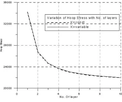
3.1.Effect of no. of layer on maximum hoop stress:
With increase in no. of shells, hoop stress reduces. But reduction in hoop stress is not uniform. For n=2,
reduction in maximum hoop stress is quite large compared to n>2. So, ‘n’ need to be optimized depending on application.
Variation of hoop stress for different no. of layer has been obtained from (2) & (6):
Table I Effect of number of shells on hoop stress at the innermost surface
No. of shells
K = Const. K = Variable
(Thickness = const.)
Max. Hoop Stress % Reduction Max. Hoop Stress % Reduction
1 235.8007 - 235.8007 -
2 184.09 22.02 184.7795 21.52
3 169.611 28.15 170.3005 27.78
4 162.7163 30.99 163.4057 30.71
5 158.5794 32.63 159.2689 32.40
Since for n=2, reduction in maximum hoop stress is 22.02 %, while for n=3 this value is 28.15 %. For n>3, decrease in hoop stress is not effective. Hence n>3 is opted only under severe condition of loading.
Rate of reduction also depends on difference between outside & inside diameter. e.g. for three layer vessel with different thickness, reduction percent is given in table II.
Table II Effect of total thickness of vessel on the effectiveness of multilayering
Sl. No. Dimension of monobloc vessel (ri, ro) in mm
Difference in radius (thickness, mm) % Reduction
n=2 n= 3
1. (152.4, 457.2) 304.8 36 45.35
2. (152.4, 297.66) 145.26 22 28.15
3. (152.4, 228.6) 76.2 12.5 16.31
4. (152.4, 165.1) 12.7(thin) 2.1 2.8
From table II, it is obvious that effect of double layering (n=2) is getting reduced from 36% to 2.1% as thickness of vessel is reduced from 304.8 mm to 12.7 mm respectively. Similar behaviour is observed in case of triple-layering of vessel. Hence, multitriple-layering is effective for greater value of overall thickness. But at the same time, overall thickness needs to be minimized so as to prevent material consumption.
3.2.Optimization of thickness of each layer
For different combinations of shell-thickness in 3-layered vessel, different value of hoop stress distribution across radial position is generated (fig. 3(a), (b)) at a given working pressure as obtained from (3) & (4). Then hoop stress under same working pressure is calculated by means of Lagrange’s multiplier method (fig. 5) and found that hoop stress throughout the thickness is less for this combination of shell-thickness. An optimization of shell-thickness is carried out with the help of Genetic Algorithm and compared with Lagrange’s multiplier [5]. This solution as obtained from GA is closer to that obtained from Lagrange’s multiplier method (Table III, & fig. 6, & 7).
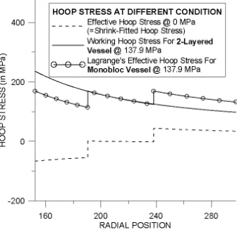
Difference in hoop stress between multilayer & monobloc vessel at each surface is known as shrinkage stress. Plot of hoop stress for different value of shell thickness:
Based on Lagrange’s -multipliers method, hoop stress distribution (based on (6), & (7)) is plotted in fig (4) and (5).
a) b)
Fig 3a) & b) Hoop stress distribution for 3-layered vessels with the given thickness (in mm) [(10, 40, 95.26) & (40, 40, 65.26) respectively]
Hoop stress distribution is analyzed for optimized thickness of multilayered vessel and then compared with that of Lagrange’s. Hoop stress distribution for the optimized thickness is validated by FE analysis of multilayered vessel of the same optimized thickness.
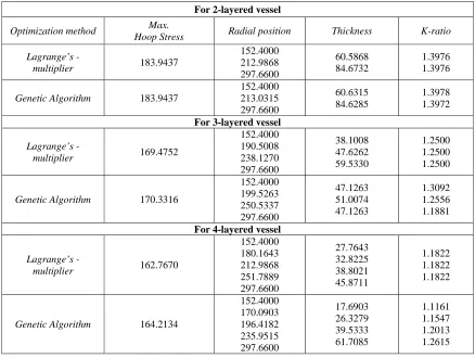
Comparison between optimum hoop stress distribution as obtained from GA, FE and Lagrange’s multipliers method is shown below (fig. (6) & (7), Table III):
Table III comparison of hoop stress as obtained by means of GA and Lagrange’s multiplier method
For 2-layered vessel
Optimization method Max.
Hoop Stress Radial position Thickness K-ratio
Lagrange’s
-multiplier 183.9437
152.4000 212.9868 297.6600
60.5868 84.6732
1.3976 1.3976
Genetic Algorithm 183.9437
152.4000 213.0315 297.6600
60.6315 84.6285
1.3978 1.3972
For 3-layered vessel
Lagrange’s
-multiplier 169.4752
152.4000 190.5008 238.1270 297.6600
38.1008 47.6262 59.5330
1.2500 1.2500 1.2500
Genetic Algorithm 170.3316
152.4000 199.5263 250.5337 297.6600
47.1263 51.0074 47.1263
1.3092 1.2556 1.1881
For 4-layered vessel
Lagrange’s
-multiplier 162.7670
152.4000 180.1643 212.9868 251.7889 297.6600
27.7643 32.8225 38.8021 45.8711
1.1822 1.1822 1.1822
Genetic Algorithm 164.2134
152.4000 170.0903 196.4182 235.9515 297.6600
17.6903 26.3279 39.5333 61.7085
1.1161 1.1547 1.2013 1.2615
Fig. (6) & Fig. (7) show the closeness of theoretical and FE analysis.
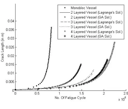
3.3.Calculation of Fatigue cycle
Nature of loading is of repeated in nature (i.e. loading-unloading in compressive zone is neglected). Hence, Δσ of equation (9) is summation of working hoop stress at 137.9 MPa and net residual stress in each cases.
Initial crack length is assumed to ao= 0.5 mm and critical crack length (af) is calculated from ASME code [ASME, (2007)]. For different cases, af are:
Monobloc Vessel: af = 36.3 mm and maximum fatigue life is 81382cycles. Two layered vessel:
o Lagrange’s solution: af = 15.1 mm and maximum fatigue life is 148270 cycles. o G A solution: af = 15.2 mm and maximum fatigue life is 148280 cycles. Three layered vessel:
o Lagrange’s solution: af = 9.5 mm and maximum fatigue life is 173450 cycles. o G A solution: af = 11.8mm and maximum fatigue life is 177210 cycles. Four layered vessel:
From above it is absolutely clear that with increase in number of layers, fatigue life increases. Above plot shows closeness of fatigue life cycle for the Lagrange’s and GA solution. Though value of Hoop stress as obtained from GA is slightly greater than that of Lagrange’s, but fatigue life cycle is greater than that as obtained from later solution (n=3).
Multilayering can be done in more effective way by shrink-fitting each autofrettaged shell of optimized thickness [Jahed et al, (2006)].
4. Conclusion
In present paper, effect of number of layers on maximum hoop stress throughout the thickness is studied and stress behaviour under different conditions is brought into focus. Effect of multilayering on fatigue life is also pointed out. From this work, following conclusions are drawn:
Maximum hoop stress at the innermost surface decreases due to multilayering.
Multilayering of vessel decreases the difference between maximum and minimum hoop stress. Thus material is safer compared to monobloc or autofrettaged vessel.
Though hoop stress decreases with increase in number of layers, but decrease in hoop stress is more effective up to n=3. Hence, number of layers used in pressure vessel depends on requirement.
Multilayering is more effective for greater values of overall thickness, but at the same time it needed to be limited.
Hoop stress at the mating surfaces for the optimized combination of thickness as obtained by GA is closer to that of Lagrange’s multiplier method.
Hoop stress distribution for optimized thickness is compared with the FE solution under the same condition of thickness and found to be almost same.
It is clear that fatigue life increases with increase in number of layers. Fatigue life for the GA solution and Lagrange’s solution is quite nearer.
References
[1] Anderson, T.L. (1994): Fracture Mechanics, Fundamentals and Applications, Third Edition, Taylor & Francis, Chapter-(10). [2] ASME (2007): An International Code, “ 2007 ASME Boiler & Pressure Vessel Code,” KD-412, pp- 74.
[3] Brownell, Llyod E.; Young, Edwin H. (2009): Equipment Design, Wiley Eastern Limited, Chapter- (15) [4] Deb, Kalyanmoy (2003):Optimization For Engineering Design, P H I Pvt. Ltd., Chapter - (6).
[5] Fryer, Donald M.; Harvey, John F. (1997): High Pressure Vessels, International Thomson Publishing, Chapter- (5). [6] Hill, R.(1998):The Mathematical Theory of Plasticity, Oxford University Press, Chapter V.
[7] Huang, Xiaoping; Koan, Torgeir (2009): Residual Stress in an Autofrettaged Tube Taking Bauschinger Effect as a function of the Prior Plastic Strain, Journal of Pressure Vessel Technology, Vol. 131, Issue 2, 021207.
[8] Huang, X. P; Cui, W. C. (2006): Effect of Bauschinger Effect and Yield Criterion on Residual Stress Distribution of Autofrettaged Tube, Journal of Pressure Vessel Technology, Vol. 128, pp. 212-216.
[9] Jahed, Hamid; Fershi, Behrooz; Karimi, Morvarid (2006): Optimum Autofrettage and Shrink-Fit Combination in Multi-layer Cylinders, Transactions of the ASME, Vol 128, pp 196-200.
[10] Troiano, Edward; Parker, Anthony P.; Underwood, John; Mossey, Charles (2003): Experimental Data, Numerical Fit and Fatigue Life Calculations Relating to the Bauschinger Effect in High Strength Armament Steel , Journal of Pressure Vessel Technology, Vol. 125,