Effect of various parameters on the
performance of capillary tube
Rahul Gulati
ME IV Semester (Heat Power Engg.) Mechanical Engineering Department Jabalpur Engineering College, Jabalpur (M.P.)
Prof. R.C.Gupta
Associate Professor Mechanical Engineering Department Jabalpur Engineering College, Jabalpur (M.P.)
Abstract :
In this paper analysis the performance of capillary tube under the different condition. The following condition : condensing temperature 40-55˚c , subcooling 0-5˚c , capillary tube diameter 1.2 – 2.4mm , mass flow rate 5 – 50 g/s , various friction factor given by different authors is used to predict the performance of capillary tube with R-22 , R-134a , R-410A refrigerant.
Key words: Capillary tube; Adiabatic; Alternative refrigerant ; Friction factor.
1.Introduction
A typical residential air conditioner consists of a compressor , evaporator , condenser and expansion devices and capillary tubes has been extensively used as the expansion device for the past flow decades. Now a day electronic expansion valves and / or short tube orifices are considered as future expansion devices for some what large size air- conditioners heat pump.
HCFC 22 has been used superior as the working fluid in residential air conditioners due to its excellent properties and fit for combining with various materials. HCFC 22 contains hydrogen and chlorine atoms and its ozone depletion potential is 0.05. Since HCFC 22 has the ozone depleting chlorine it is to be phased out eventually according to the montreal protocol amendments adopted by the participating countries [1]. The alternative of HCFC 22 are HFC 134a , R-407C (23% R-32/25% R-125/52% HFC-134a) and R-410A (50%R-32/50%R-125).
Nomenclature
A=cross-sectional area of inside of tube, m2 D=ID of tube, m
f = friction factor, dimensionless h = enthalpy, KJ/Kg
hf = enthalpy of saturated liquid, KJ/Kg
hg= enthalpy of saturated vapor, KJ/Kg
∆L = length of increment , m P = pressure , Pa
Re = Reynolds number v = specific volume , m3/kg
vf= specific volume of saturated liquid, m
3
/kg vg = specific volume of saturated vapor, m3/kg
V = velocity of refrigerant, m/s W= mass rate of flow, kg/s
x = fraction of vapor in mixture of liquid and vapor µ = viscosity, Pa.s
µf= viscosity of saturated liquid, Pa.s
2. Mathematical modeling
Initially, a generalized mathematical model has been developed for straight capillary tube and for other geometries like helical and spiral capillary tubes the necessary modifications have been made in the developed model for the flow through a straight capillary tube.
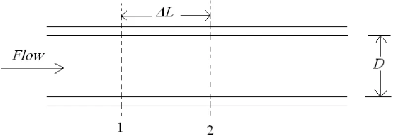
The fundamental equations applicable to the control volume bounded by point 1 and 2 in fig. (A) are (1) conservation of mass,(2) conservation of energy, and (3) conservation of momentum.
Figure 1 :- Incremental length of capillary tube
.
The equation for conservation of mass states that
W = V1A/v1 = V2A/v2 (1)
W/A = V1/v1 = V2/v2 (2)
And W/A will be constant throughout the length of the capillary tube.
The statement of conservation of energy is
1000h1+ V12/2 = 1000h2+ V22/2 (3)
Which assumes negligible heat transfer in and out of the tube.
The momentum equation in words states that the difference in forces applied to the element because of drag and pressure difference on opposite ends of the element equals that needed to accelerate the fluid
[(p1- p2) – f(∆L/D)(V 2
/2v)]A = W(V2-V1) (4)
As the refrigerant flows through the capillary tube , its pressure and saturation temperature progressively drop and the fraction of vapor x continuously increases. At any point
h = hf(1-x) + hg x (5)
and
v=vf (1-x) + vg x (6)
In Eq. (4) V, v , and f all change as the refrigerant flows point 1 to point 2 but some simplification results from Eq .(2) which shows that V/v is constant so that
f(∆L/D)(V2/2v)= f(∆L/D)(V/2)(W/A) (7)
Vm = (V1+V2)/2 (8)
Since expressing the friction factor f for the two phase flow is complex, we shall use different friction factor to predict the performance of capillary tube given by Erth [2] , Sami [3] , Pate [4] , Hopkins [5] respectively .
f = 3.1/Re0.5 Exp((1.0-x0.25/2.4)) f = 3.1/[Re(1-x)]0.5 Exp((1.0-x0.25)/2.4) f = 3.4/Re.47
f = .217/Re0.2 (9)
The viscosity of the two-phase refrigerant at a given position in the tube is a function of the vapor fraction x. viscosity of the two-phase can be calculated by Mcadams et al. [6] or Duckler et al. [7]
µ = µf (1-x) + µg x (10)
The mean friction factor fm applicable to the increment of length
1-2 is
fm = (f1+f2)/2 (11)
2.1 Calculating the length of an increment
The essence of analytical calculation method is to determine the length of the increment 1-2 in Fig. (A) for a given reduction in saturation temperature of the refrigerant. The flow rate and all the conditions at point 1 are known, and for an arbitrarily selected temperature at point 2 the remaining conditions at point 2 and the ∆L will be computed in the following specific steps.
1. Select t2 .
2. Compute p2 , hf2, hg2 , vf2 , and vg2, all of which are function of t2 .
3. Combine the continuity equation (2) and the energy equation (3)
1000h2 + (v22/2)(W/A)2 = 1000h1+ V12/2 (12)
Substitute Eqs. (5) and (6) into Eq. (12)
1000hf2+1000(hg2-hf2) x+[vf2+(vg2-vf2)x]2/2(W/A)2 = 1000h1+ V12/2 (13)
Everything in Eq.(13) is known except x , which can be solved by the quadratic equation
x = [-b ± √(b2-4ac)]/(2a) (14)
where
a = (vg2-vf2) 2
(W/A)2(1/2)
b = 1000(hg2-hf2) + vf2 (vg2-vf2) (W/A)2
c = 1000(hf2-h1) + (W/A) 2
(1/2) vf2 2
– V1 2
4. With the value of x known, h2, v2, and V2 can be computed.
5. Compute the Reynolds number at point 2 using the viscosity from Eq. (10) , the friction factor at point 2 from Eq. (9) , and the mean friction factor for the increment from Eq. (11).
6. Finally, substitute Eq. (7) and Eq. (8) into Eq. (4) to solve for ∆L.
3. Analysis of the calculation results
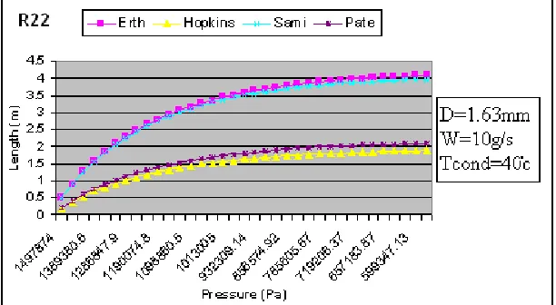
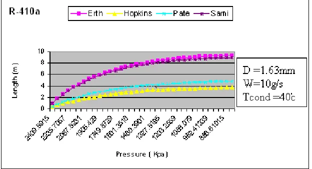
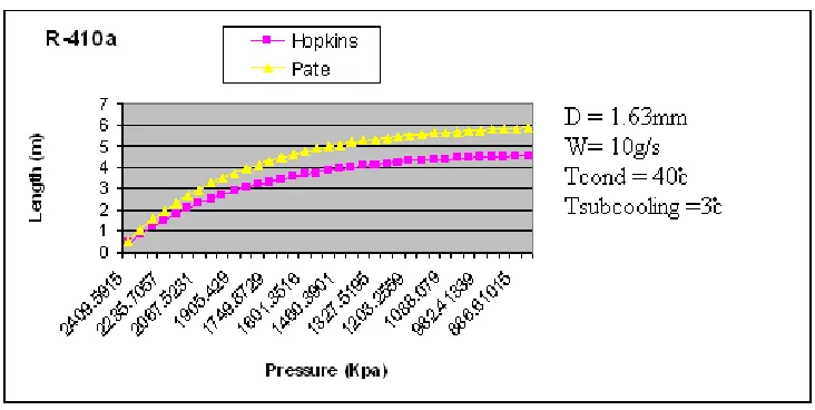
In order to analysis the performance of adiabatic capillary tube different parameter are used with different friction factor given by authors. Performance of capillary tube with 0˚c subcooling , D=1.63mm, w =10g/s, Tcond=40˚c is shown by Fig. 2 to 4 and with 3˚c sub cooling, D=1.63mm, w =10g/s, Tcond=40˚c is shown by Fig. 5 to 7.
Fig. 2 Pressure variety versus the increment of capillary tube length without subcooling for R-22
Fig. 4 Pressure variety versus the increment of capillary tube length without subcooling for R-410a
Fig. 5 Pressure variety versus the increment of capillary tube length with subcooling for R-22
Fig. 7 Pressure variety versus the increment of capillary tube length with subcooling for R-410a
4. Conclusions
In this paper, the performance of adiabatic capillary tubes used is predicted for R-22, R-134a , R-410A. The following conclusions can be drawn.
(1) Duckler’s equation is not better than McAdams’ equation for two -phase viscosity calculation. (2) Kinetic energy term in energy conservation equations is not impacting on the final results.
(3) pressure drop due to area contraction is impacting on the model so it needs to be considered in the model.
(4) Erth [2]and sami [3] friction factor can not take for predicting the performance of capillary tube under the any subcooling condition.
(5) From the above analysis for predicting the performance of capillary tube Hopkins [5] friction factor gives optimum result under the all conditions.
References
[1] United Nations Environment Programme, Decisions of the Fourth Meeting of the Parties to the Montreal Protocol on substances that
deplete the ozone layer, Copen-hagen, Denmark ,1992.
[2] Erth RA. Two-phase flow in refrigeration capillary tubes: analysis and prediction. Doctoral dissertation, Purdue University, 1970.
[3] Sami SM. Private communication, Moncton University, Moncton, Canada.
[4] Melo c, Ferreira RTS, Boabaid Neto c, Goncalves JM, Thiessen MR. (1994) Experimental analysis of Capillary tubes for CFC-12 and
HFC-134a. p.347±52.
[5] Hopkins NE. (1950) Rating the restrictor tube method of determining flow capacities for Freon-12 and Freon-22. Refrigerating
Engineering 58(11) : 1087± 95
[6] Stoecker WF , Jones JW. (1982) Refrigeration and air conditioning. 2nd
ed. McGraw Hill. p.260±72.
[7] Collier Gj ,Thome JR. (1996) Convective boiling and condensation. 3rd