Analysis of ECRH Pre-Ionization for Plasma Start-Up in JT-60SA
∗
)
Kazuyoshi HADA, Kazunobu NAGASAKI
1), Kai MASUDA
1), Ryota KINJO, Shunsuke IDE
2)and Akihiko ISAYAMA
2)Graduate School of Energy Science, Kyoto University, Uji, Kyoto 611-0011, Japan
1)Institute of Advanced Energy, Kyoto University, Uji, Kyoto 611-0011, Japan 2)Japan Atomic Energy Agency, Naka, Ibaraki 311-0193, Japan
(Received 9 December 2011/Accepted 31 May 2012)
Plasma start-up assisted by electron cyclotron resonance heating (ECRH) pre-ionization is theoretically stud-ied for the superconducting tokamak JT-60SA by using a zero-dimensional (0-D) model. Because the toroidal electric field is limited to 0.5 Vm−1, we clarify the conditions for a robust plasma initiation. Five temporal
equations are solved for a spatially-uniform plasma: the electron and neutral density equations, the electron and ion energy density equations, and the electric circuit equation. The numerical calculation results show that an absorbed ECRH power of 150 kW is required to start up the plasma, assuming an initial neutral density of 3.0×10¹⁸m−3, and that reducing the oxygen and carbon impurity densities facilitates successful start-up. We
discuss the dependence of the absorbed ECRH power on the neutral density and impurities. The simulation qualitatively reproduces experimental results from JT-60U.
c
2012 The Japan Society of Plasma Science and Nuclear Fusion Research
Keywords: pre-ionization, electron cyclotron resonance heating, superconducting tokamak, JT-60SA, zero-dimensional model
DOI: 10.1585/pfr.7.2403104
1. Introduction
Plasma is initiated by a loop voltage generated by solenoid coils in tokamaks. In superconducting tokamaks, which aim at steady-state operation, the loop voltage gen-erated for plasma breakdown is lower than that of normal conducting tokamaks due to a limited current ramp rate and thick vacuum vessel wall. Therefore it is difficult to start up plasmas if the radiation loss is large, that is, if the vac-uum chamber wall is not in good condition. To ensure re-liable plasma breakdown, pre-ionization using electron cy-clotron resonance heating (ECRH) has been proposed, and successful start-up with ECRH at a low loop voltage has been demonstrated in normal conducting tokamaks such as JT-60U [1] and DIII-D [2] and in the superconducting tokamak KSTAR [3]. In the International Thermonuclear Experimental Reactor (ITER), the toroidal electric field is limited to 0.3 Vm−1, and pre-ionization using 170 GHz
ECRH is planned for plasma start-up [4]. Because the JT-60SA superconducting tokamak, which is now under con-struction at the JAEA [5], also has a limited toroidal elec-tric field (0.5 Vm−1), we need to clarify the conditions for
robust plasma initiation. Application of the second har-monic 110 GHz ECRH is under consideration for reliable start-up. However, it is not yet clear how much ECRH power is necessary for plasma start-up and how plasma conditions such as impurities affect the plasma start-up.
A zero-dimensional (0-D) model that describes author’s e-mail: [email protected]
∗)This article is based on the presentation at the 21st International Toki
Conference (ITC21).
ECRH-assisted start-up in ISX-B was proposed by Kulchar et al. [6], and more advanced models were developed by Lloyd et al. [7] and Bae et al. [8]. Lloyd et al. included the effects of impurities, and Bae et al. considered the er-ror field effects and poloidal field coil circuit equations. In this paper, we study plasma start-up assisted by ECRH pre-ionization in JT-60SA (major radius, R0=2.97 m;
mi-nor radius, a=1.18 m; and toroidal magnetic field, BT =
2.25 T) by using a 0-D model. The model consists of the electron and neutral (hydrogen atom) density equations, the electron and ion (hydrogen ion) energy density equa-tions, and the electric circuit equation. The main purposes of this paper are to examine the conditions for reliable start-up in JT-60SA and clarify the dominant physical pro-cess in ECRF plasma initiation.
This paper is organized as follows. The 0-D model is described in Sec. 2, and the calculation results are dis-cussed in Sec. 3. The conclusion is presented in Sec. 4.
2. Zero-Dimensional (0-D) Model
The ECRH pre-ionization effects are theoretically in-vestigated by a 0-D model to examine the conditions for a reliable start-up in JT-60SA and to understand the physical process. The 0-D model consists of five temporal equa-tions: the electron and neutral density equations, the elec-tron and ion energy density equations, and the electric cir-cuit equation. These equations are solved for spatially-uniform plasma. In this model, we assume that the ma-jor and minor radii remain constant and all of the injectedc
2012 The Japan Society of Plasma
ECRH power is absorbed.
The electron density neis given by
dne
dt =S n0ne−
ne
τp,
(1) where n0 is the neutral density, the particle confinement
timeτp is considered as 100 ms, and S is the coefficient
rate for electron ionization, given by
S = 2×10
−13
6+Te/13.6
Te
13.6exp
−13.6
Te
. (2)
Teis the electron temperature in electronvolts.
We assume that the total number of particles are con-served,
dn0
dt =− dne
dt . (3)
The impurity density assumed to be much smaller than the hydrogen density.
The electron and ion temperatures are determined by the electron and ion energy density equation,
dUe
dt =pECRH+pOH−pIONIZ−pBREM
−pIRAD−pEQU−Ue(νerr+νdr+νE), (4)
dUi
dt =pEQU−pCX−UiνE, (5) where Ue=3neTe/2 is the electron energy density and Ui
=3niTi/2 is the ion energy density. Here pECRHis the
ab-sorbed ECRH power density. Because the electron density and temperature vary with time, the ECRH power absorp-tion efficiency can be considered in future. The ohmic heating power density pOH is given by pOH = I2pRp/Vp,
where Rp is the plasma resistance, and Vp is the plasma
volume.
The ionization and radiation loss pIONIZis given by
pIONIZ=
Vn
Vp
n0neS WD, (6)
where Vnis the volume occupied by neutrals, and WD, the
total energy lost per ionization, is considered to be 30 eV. The bremsstrahlung power loss pBREMis given by
pBREM=1.53×10−38neTe1/2
⎛ ⎜⎜⎜⎜⎜ ⎝nD+
I nI Z2
I ⎞ ⎟⎟⎟⎟⎟ ⎠, (7) where nD is the hydrogen ion density, and Z2
I is the mean-square charge.
The line radiation loss through the interaction between electrons and impurity ions pIRADis given by
pIRAD=nenI ×10f, (8)
where f =−33.93+4.888Q−2.432Q2 +0.3697Q3for
the carbon impurity and f =−34.06+4.194Q−1.827Q2
+0.2467Q3for oxygen impurities with Q=log T e. The
impurity density nI is treated as nI = fIne, where fI is the ratio of the impurities to the electron density.
The equipartition loss transferred from electrons to ions pEQUis given by
pEQU=7.75×10⁻³⁴(Te−Ti)
nelnΛ
Te3/2
×
⎛ ⎜⎜⎜⎜⎜ ⎜⎜⎝nD
2 +
I nI Z2
I AI
⎞ ⎟⎟⎟⎟⎟
⎟⎟⎠, (9)
where lnΛis the Coulomb logarithm, and AI is the impu-rity ion mass number.
The charge exchange loss between hydrogen atoms and hydrogen ions pCXis given by
pCX=
Vn
Vp
enDn0(Ti−T0) SCX, (10)
where T0 is the temperature of background neutrals, and
SCXis the rate coefficient for charge exchange,
SCX=1.066×10⁻¹⁴Ti0.327. (11)
For the detailed formulae, see [7, 8]. In the initial phase, the error field causes direct connection of the field lines to the vacuum chamber wall; consequently, the electrons escape from the plasma along the lines. The error field loss rateνerris given by
νerr=
δB
B VT
a 1−
Ip
Ic
, (12)
for Ip < ICand byνerr=0, for Ip > IC, where VT is the
thermal velocity of electrons, and ICis the critical current,
IC=4πaδB/μ0. The drift loss rate due to gradB drift and
curvature drift [9],νdr, is given by
νdr=4.95×10⁻⁹
Te
aR0B.
(13) HereνEis the energy loss rate given by the empirical law
based on “neo-Alcator scaling”.
The electric circuit equation is given by dIp
dt =
VL−IpRp
L , (14)
where VLis the applied loop voltage, and L is the plasma
inductance,
L=μ0R0
ln8R0
a −1.75
. (15)
Although the plasma inductance is a strong function of the current profile and varies rapidly with time as the current channel forms, for simplicity, we assume a flat current pro-file and treat the plasma inductance as a constant. The plasma inductance is L=4.67µH for R0 =2.97 m and a
=1.18 m.
3. Simulation Results
3.1
Simulation results for JT-60SA
We calculated plasma start-up using the 0-D model with the JT-60SA parameters. Figure 1 shows the temporal behavior of the loop voltage and absorbed ECRH power. The ECRH power was turned on at t=0.0 s; that is, it was applied before the loop voltage is turned on. The loop volt-age of approximately 9 V, which corresponds to 0.5 Vm−1, was applied from t=0.05 s to 0.15 s. We scanned the ini-tial electron temperature and density in the range of Te=
0.1-2.0 eV, from ne=1.0×10¹⁵to 1.0×10¹⁷m−3and
con-firmed that these changes have little impact on the temporal behavior of the main variables. We assume the following initial parameters: an electron density of 1.0×10¹⁶m−3,
a neutral density of 3.0×10¹⁸m−3, electron and ion
tem-Fig. 1 Temporal behavior of the loop voltage and the absorbed ECRH power.
(a)
(b)
Fig. 2 (a) Time evolution of electron and neutral densities for a
successful start-up. Absorbed ECRH power is pECRH =
400 kW. (b) Time evolution of electron and ion temper-atures and current for a successful start-up. Absorbed
ECRH power is pECRH=400 kW.
peratures of Te = 1.0 eV and Ti = 1.0 eV, respectively,
carbon and oxygen densities of 0.1% of the electron den-sity, and an absorbed ECRH power of pECRH=400 kW. In
this paper, we define successful start-up as occurring when the electron temperature becomes sufficiently high, so that
pIRADis no longer a large fraction of the total power loss
from the plasma. This generally applies when Te>100 eV.
Figure 2 shows the temporal behavior of the electron and neutral densities, the electron and ion temperatures, and the plasma current in a successful start-up. The electron den-sity rises promptly to near 3.0×10¹⁸m−3, and the neutral
density decreases with increasing electron density. These electrons are produced by pre-ionization using ECRH. In contrast, when the ECRH power is reduced, the discharge fails. Figure 3 shows the temporal behavior of the elec-tron and neutral densities, elecelec-tron and ion temperatures, and plasma current in an unsuccessful start-up. In the ini-tial phase, the line radiation power due to impurity ions, ionization power, and equipartition power are the domi-nant losses in the electron energy density equation. In this case, the plasma cannot overcome the radiation barrier. The electron energy density is much smaller than that in successful start-up, and the electron temperature remains low.
Figure 4 shows the dependence of the electron tem-perature and plasma current at t =1.0 s on the absorbed ECRH power. The initial conditions are an electron density of 1.0×10¹⁶m−3 and a neutral density of 3.0×10¹⁸m−3.
The carbon and oxygen densities are the same as that
(a)
(b)
Fig. 3 (a) Time evolution of electron and neutral densities for an
unsuccessful start-up. Absorbed ECRH power is pECRH=
100 kW. (b) Time evolution of electron and ion tempera-ture and plasma current for an unsuccessful start-up.
Fig. 4 Electron temperature and plasma current at t=1.0 s.
Fig. 5 Electron temperature at t=1.0 s for a neutral density of
2.0-5.0×10¹⁸m−3.
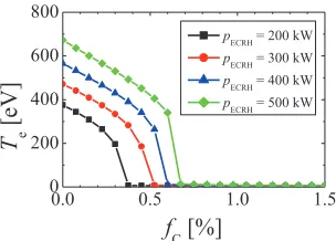
Fig. 6 Electron temperature as a function of the fraction of car-bon impurities for an absorbed ECRH power of 200-500 kW.
shown in Fig. 2. The figure reveals a threshold in ECRH power for successful start-up; an ECRH power of approxi-mately 150 kW is required when the initial neutral density is 3.0×10¹⁸m−3.
Figure 5 shows the electron temperature at t=1.0 s versus the absorbed ECRH powers. The initial neutral density was scanned from 2.0×10¹⁸m−3to 5.0×10¹⁸m−3.
More ECRH power is required as the initial neutral den-sity increases because the radiation power loss increases. Below the threshold power, the radiation barrier cannot be overcome, and the electron temperature remains as low as 1 eV. Impurities have an important role in plasma start-up. Figures 6 and 7 show the electron temperature at t=1.0 s for various ratios of impurities to the electron density. The ratios of carbon and oxygen impurities to the electron den-sity were varied between 0.0% and 1.5%. The effect of
car-Fig. 7 Electron temperature as a function of the fraction of oxygen impurities for an absorbed ECRH power of 200-500 kW.
Fig. 8 Temporal behavior of the plasma current for JT-60U.
bon impurities is slightly larger than that of oxygen impu-rities. When the carbon impurities were more than 0.5% of the electron density, the required ECRH power was more than 300 kW. Suppression of oxygen and carbon impurities would be useful to ensure successful start-up and reduce the required ECRH power.
3.2
Comparison with JT-60U experimental
results
To validate the 0-D model used in this paper, we cal-culated the plasma start-up in JT-60U by using the 0-D model and compared it with the experimental results. We assumed a major radius of R0=3.05 m, a minor radius of a
=0.72 m, a self-inductance of 5.49µH, an initial electron density of 1.0×10¹⁶m−3, and no impurities. Two types of start-ups were calculated: ECRH-assisted start-up with an ECRH power of 950 kW (from t=0.23 s), a loop volt-age of 4 V (t=0.25-0.35 s), and an initial neutral density of 0.64×10¹⁸m−3; and OH start-up with a loop voltage of
25 V (t=0.25-0.33 s) without ECRH power, and with an initial neutral density of 1.4×10¹⁸m−3. Figure 8 shows
is not yet clear whether this is a realistic value because we have not considered the effects of the eddy current or the radial profile in the 0-D model. A one dimensional model considering the radial structure is now under development for more quantitative estimation.
4. Conclusion
We investigated the effects of ECRH pre-ionization on plasma start-up using the JT-60SA parameters and a 0-D model. The calculation shows that the ECRH power is ef-fective for plasma start-up under low loop voltage condi-tions. An ECRH power of 150 kW is required to start up the plasma for ne=3.0×10¹⁸m−3. There is a threshold
in ECRH power for a successful start-up. The threshold depends on the initial neutral density, and greater ECRH power is required as the initial neutral density increases. In addition, it depends on the carbon and oxygen impurity densities because the radiation loss increases with increas-ing impurity densities. This implies that for a reliable start-up, it is important to control the neutral density and reduce
the impurity densities. The calculation using the JT-60U parameters qualitatively reproduced the time evolution of the experimental results. For a more quantitative and de-tailed analysis, the 0-D model will be extended to a 1-D model.
Acknowledgement
This work was partially supported by collaboration re-search of JT-60SA.
[1] K. Kajiwara et al., Nucl. Fusion. 45, 694 (2005). [2] G.L. Jackson et al., Nucl. Fusion. 47, 257 (2007). [3] Y.S. Bae et al., Nucl. Fusion. 49, 022001 (2009). [4] Y. Gribov et al., Nucl. Fusion. 47, S385 (2007). [5] S. Ishida et al., Nucl. Fusion. 51, 094018 (2011). [6] A.G. Kulchar et al., Phys. Fluids 27, 7 (1984).
[7] B. Lloyd et al., Plasma Phys. Control. Fusion. 38, 1627 (1996).
[8] Y.S. Bae et al., IEEE Trans. Plasma Sci. 31, 4 (2003). [9] F.F. Chen, Introduction to Plasma Physics and Controlled