E
ff
ect of High Ion Temperature on the Polytropic Coe
ffi
cient in the
End Region of GAMMA 10
/
PDX
∗
)
Kunpei NOJIRI, Mizuki SAKAMOTO, Naomichi EZUMI, Satoshi TOGO, Takaaki IIJIMA,
Seowon JANG, Akihiro TERAKADO, Yosuke KINOSHITA, Toshiki HARA,
Tomonori TAKIZUKA
1), Yuichi OGAWA
2)and Yousuke NAKASHIMA
Plasma Research Center, University of Tsukuba, Tsukuba 305-8577, Japan1)Graduate School of Engineering, Osaka University, Suita 565-0871, Japan 2)Graduate School of Frontier Sciences, University of Tokyo, Kashiwa 277-8568, Japan
(Received 30 September 2018/Accepted 9 January 2019)
The effect of high ion temperature on the ion polytropic coefficient (γ) was experimentally investigated in the end region of the GAMMA 10/PDX tandem mirror. The ion temperature parallel to the magnetic field (Ti||)
was varied using the ion cyclotron range of frequencies (ICRF) waves, which heat the plasma in the central cell, and by applying an additional gas puffin the central cell. Assuming the ion sound speed,γTi||was evaluated by
a Langmuir probe, andTi||was evaluated in an ion energy analyzer. These parameters were combined to evaluate
γ. The time evolutions ofγTi||obtained from the probe andTi||obtained from the energy analyzer were similar.
The plasma in the end region can be regarded as collisionless, butγwas lower with ICRF heating than without the heating. A highTi||component was identified in the heated case. As mentioned in a previous numerical study
[B. Linet al., Phys. Plasmas23, 083508 (2016)], it is experimentally suggested thatγcan be reduced by the high Ti||component resulting from the ICRF heating.
c
2019 The Japan Society of Plasma Science and Nuclear Fusion Research
Keywords: ion temperature, ion polytropic coefficient, sound speed, Langmuir probe, ion energy analyzer DOI: 10.1585/pfr.14.2401086
1. Introduction
The ion sound speed (Cs) [1–3] is an important
pa-rameter in boundary plasma physics related to sheath phe-nomena. It is a function of the electron temperature Te, the ion temperature parallel to the magnetic fieldTi||,
and the ion polytropic coefficient γ. Specifically, Cs =
{(kTe+γkTi||)/mi}1/2, wherekis the Boltzmann constant
[2,3]. Theoretical and numerical studies using plasma fluid models have shown that the sheath characteristics are af-fected by ion temperature Ti[4–7] and γ[8]. In a
one-dimensional (1D) particle model, the authors of [9] also showed that the hotTi|| component, which is higher than Te, imparts strong kinetic effects and reduces theγin
col-lisionless plasma below the widely used value in 1D adia-batic flow, where the temperature is anisotropic andγ=3 in the flow direction. However, as experimental investiga-tion of this phenomenon is lacking, investigating the effect of highTi||onγandCsis important.
Langmuir probes (LPs) are widely used for measur-ing basic plasma parameters such asTe, the electron
den-sity (ne), and ion particle flux. The drift speed of ions
flowing into the LP reachesCsand the ion saturation
cur-rent reflects the value ofCs. Therefore, whenTi|| is
non-author’s e-mail: [email protected]
∗)This article is based on the presentation at the 12th International
Con-ference on Open Magnetic Systems for Plasma Confinement (OS2018).
negligible compared toTe, there is a possibility to evaluate
γTi||using the LP.
GAMMA 10/PDX is a tandem mirror device in which the plasmaTi exceeds the plasmaTe[10, 11]. In a
typi-cal discharge,TiexceedsTeby one order of magnitude or
more. Furthermore,Tican be varied by applying the
heat-ing system usheat-ing the ion cyclotron range of frequencies (ICRF).
In this study, we attempt to evaluate the effect of high Ti||onγusing an LP and an ion energy analyzer in the end
region of GAMMA 10/PDX.
2. Experimental Device and
Diagnos-tics
2.1
GAMMA 10
/
PDX tandem mirror
Figure 1 shows schematics of (a) part of the GAMMA 10 tandem mirror and (b) its magnetic field. The device consists of a central cell, anchor cells, plug/barrier cells and end regions. The device is 27 m long and the volume of the vacuum vessel is 150 m3. The main plasma
produc-tion, ICRF heating of the plasma, and hydrogen gas puff -ing are applied in the central cell. The anchor cells have a minimum-B configuration and maintain the stability of the plasma. The present experiment employed two types of ICRF heating systems: one that produced the plasma and heated it in the anchor cells, and another that heated the
c
2019 The Japan Society of Plasma
plasma in the central cell. Hereafter, the former and latter are referred to as RF1 and RF2, respectively. The stan-dard discharge in GAMMA 10/PDX employs both RF1 and RF2.
In the west-end region, an LP and an ion energy an-alyzer named end loss ion energy anan-alyzer [10, 12] are in-stalled. The analyzer is hereinafter referred to IEA. The LP is installed near the roof target of the divertor simulation experimental module (D-module [10, 11]; see Fig. 1 (c)). The vertical position of the D-module and the probe are adjustable. The tungsten LP electrode is 1.5 mm in diame-ter and 1.1 mm long. The IEA is schematized in Fig. 1 (d). Ions with lower energy than the effective potential energy at the ion repeller grid are reflected and collected at the col-lector plate. In this study,Ti||was evaluated by Maxwellian
fitting of the energy spectra measured by the IEA. When two components of the Maxwellian distribution were iden-tifiable, we calculated the effective Ti|| from the relative
densities of the components.
2.2
Evaluation of
γ
T
i||using a Langmuir
probe
The ion and electron saturation currents (Iis andIes,
respectively) of the hydrogen plasma are respectively given by
Iis=
1 2Sene
kTe+γkTi
mi
, (1)
Ies=
1 4Sene
8kTe
πme
, (2)
whereS is the effective probe surface area, andmiandme
are the ion and electron masses, respectively. The surface areas ofIisandIesare assumed identical. The coefficient
1/2 of Eq. (1) is the ratio of the density at the sheath edge
Fig. 1 Schematics of (a) part of the GAMMA 10/PDX tandem mirror, (b) magnetic field distribution in part (a), (c) Langmuir probe installed near the roof target, and (d) end-loss ion energy analyzer.
to the upstream density derived from the conservative form of the momentum equation [13]. The values ofIis,Iesand
necan be obtained from the LP current-voltage
character-istics. In this study,newas evaluated fromIesandTeusing
Eq. (2). Combining Eqs. (1) and (2),γTi|| is calculated as
follows:
γTi=
⎡ ⎢⎢⎢⎢⎢ ⎣π2mmi
e
Iis
Ies
2
−1 ⎤ ⎥⎥⎥⎥⎥
⎦Te. (3)
3. Experimental Results and
Discus-sion
3.1
T
ivariation by ICRF heating and
addi-tional gas pu
ff
in the central cell
In the experiment, theTi||of the end-loss plasma was
varied by applying RF2 and an additional hydrogen gas puffin the central cell. The plasma discharge was con-ducted with or without RF2 (RF1 was applied in both dis-charges). The additional gas in the central cell was sup-plied from timet=160 tot=240 ms at a plenum pressure of 70 Torr. Figure 2 shows typical time evolutions of the diamagnetism (DMCC) in the central cell (a), electron line
density (NLCC) in the central cell (b), and theTi||(c) and
particle flux (d) measured by the IEA (Ti||,IEA andΓi||,IEA,
which meanTi||andΓi||at the end plate, respectively). The
temporal evolutions of DMCC andNLCCwere those of a
typical discharge. TheTi||,IEA andΓi||,IEA data were
aver-Fig. 2 Time evolution of (a) diamagnetism and (b) electron line density of plasma in the central cell; (c) ion temperature parallel to the magnetic fieldTi||and (d) ion particle flux Γi||at the end plate, measured by the IEA in the west end
Fig. 3 Typical current-voltage characteristics of the LP.
aged over three similar discharges. TheDMCCwas higher
with the RF2 than without the RF2, indicating a higherTi
of the central plasma in the former operation. Supplying additional gas reduced theDMCC in the setup with RF2.
TheNLCC was also higher with the RF2 than without the
RF2. In both discharges, the additional hydrogen gas in-creased theNLCC. In the west-end region without the
addi-tional gas,Ti||,IEAandΓi||,IEAwith the RF2 were higher than
those without RF2. TheTi||,IEA with RF2 was higher than
without RF2 by virtue of a high-temperature component that was not identified in the absence of RF2. The details are described in Sec. 3.3. The gas supply in the central cell reduced theTi||,IEAandΓi||,IEAin the RF2 operation. In the
no-RF2 operation, the additional gas slightly decreased the Ti||,IEAand increased theΓi||,IEA. Both values became
simi-lar to those with the RF2. In the absence of the gas puff, the Ti||,IEAvalues with and without the RF2 were∼240 eV and
∼140 eV, respectively. When the gas was supplied,Ti||,IEA
was∼130 eV in both the RF2 and no-RF2 operations.
3.2
Langmuir probe analysis
Figure 3 shows the typical LP current (Ip)-voltage (Vp)
characteristics measured at t = 120-140 ms during the shots of IEA in the RF2 operation. TheIp-Vp
character-istics were analyzed by the standard procedure described in Ref. [14]. To avoid the error resulting from sheath ex-pansion,Iiswas derived from the linearly fitted current at
Vp = Vf, whereVf is the floating potential. Meanwhile,
the electron currentIeswas determined atVp =Vs, where
Vsis the space potential. Having determinedIesandTe,ne
was determined by rearranging Eq. (2). To compensate the magnetic field effect on the collection area of the electrons (and consequently onne),S was taken as the projected area
of the magnetic field line on the probe surface.
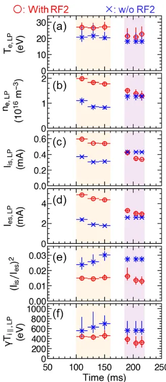
Figures 4 (a)-(e) show the time evolutions ofTe,ne,Iis
andIes, and (Iis/Ies)2 obtained from the LP. Each dataset
was measured during the shots of the IEA, and the error bars were obtained from the fitting errors. In the period without the additional gas puffin the central cell,Tewas
∼30 eV with the RF2 and∼20 eV without the RF2. During
Fig. 4 Time evolutions of (a) Te, (b) ne, (c) Iis, (d) Ies, (e)
(Iis/Ies)2, (f)γTi||evaluated using a Langmuir probe. Red
circles: with RF2; blue crosses: without RF2.
the same period, ne was ∼2×10¹⁶m−3 and∼1×10¹⁶m−3
with and without the RF2, respectively. In both discharges, Tedecreased when the additional gas was supplied. At that
time, ne slightly decreased with the RF2 and slightly
in-creased without the RF2, such that the twone converged.
In the period without the gas puff, Iis and Ies were both
higher in the RF2 than in the no-RF2 operation. When the gas was supplied, the Iis values in both discharges were
almost identical. The determination ofγTi||in Eq. (3)
cru-cially depends on the parameter (Iis/Ies)2. The square of
the current ratio was lower with the RF2 than without the RF2 throughout the discharge. Substituting the above pa-rameters in Eq. (3), we obtain γTi||. Figure 4 (f) shows
the time evolution ofγTi|| obtained from the LP (γTi||,LP).
When the gas was supplied in the central cell,γTi||,LP
de-creased over time with the RF2, but was relatively stable without the RF2. Similar tendencies were observed inTi||
evaluated by the IEA. On the other hand, in the period without the additional gas puff(t = 100-160 ms), γTi||,LP
val-Fig. 5 Time evolutions of (a) evaluated ion polytropic coeffi-cient and (b)ne,LP/Ti||,IEA2, which is proportional to
col-lisionality. Red circles: with RF2; blue crosses: without RF2.
ues of γTi||,LP with and without RF2 were ∼440 eV and
∼620 eV, respectively.
3.3
Evaluation of
γ
using the Langmuir
probe and ion energy analyzer
To obtainγ, we assumed that theTi|| values near the
LP and IEA were nearly identical, and dividedγTi||,LPby
Ti||,IEA. Figure 5 (a) shows the time evolution of the
evalu-atedγ. In the RF2 operation,γwas∼1.8 in the first period, increasing to∼2.5 during the gas supply. In no-RF2 opera-tion,γwas approximately 4.4. Since there are large errors inγdue to the fitting errors of the LP, we qualitatively an-alyzeγ with and without RF2 in the period without the additional gas.
First, we consider the characteristics ofγin the widely used plasma fluid model [2,3,13]. In this model,γdepends on the ion-ion collisionalityL/λi-I ∝ n/Ti2. Asn/Ti2
in-creases,γdecreases from 3 to 1. Figure 5 (b) shows the time evolution of ne,LP/Ti||,IEA2, the quotient of ne
mea-sured by the LP andTi||,IEA2 measured by the IEA. The
ne,LP/Ti||,IEA2 values were almost unchanged by the
addi-tional RF2 system. The collision times in both cases (with and without the RF2) were∼400 ms or longer. As the colli-sion time markedly exceeded the discharge time (200 ms), the plasmas in both cases were always collisionless. There-fore, the differentγvalues between the RF2 and no-RF2 operations were caused by other factors.
Next, we consider the effect of the high-temperature component of the ions onγ, mentioned in Ref. [9]. The
Fig. 6 Normalized ion energy spectra (a) with RF2 and (b) with-out RF2, measured by the IEA. The normalization factor was the peak value of the corresponding spectrum.
authors of [9] suggested that a highTicomponent in
col-lisionless plasma would reduce γbelow its value in the widely used model. Figures 6 (a) and (b) show the en-ergy spectra obtained by the IEA in the RF2 and no-RF2 operations, respectively. The spectra were collected from t = 120 to 140 ms and normalized by their peak values. Without RF2, the spectrum was a single Maxwellian dis-tribution ofTi|| ∼150 eV, whereas the RF2 spectrum was
the convolution of two Maxwellian distributions of Ti||
∼130 eV and ∼570 eV. Together with the result in Ref. [9], this result suggests that γ was lowered by a high-temperature ion component resulting from the ICRF heat-ing.
Without the RF2, the evaluated γ exceeded 3.0, the upper limit in the plasma fluid model. In order to clarify the reason for this discrepancy, it requires a more quanti-tative investigation. In this study, we assumed that theTi||
values were almost the same at the LP and the IEA. If there was a largeTi||gradient in the setup without RF2, the
evaluatedγwould change. The spatial distribution ofTi||
can be investigated using numerical simulations. In addi-tion, the measurements were performed in an expanding magnetic field. In such a magnetic field, ion flow accel-eration [15] and a diamagnetic property of electrons [16] have been confirmed in the lowerTi plasma. Elucidating
these effects in the highTi||plasma also requires a kinetic
4. Summary
We experimentally investigated the effect of high Ti
on the ion polytropic coefficient (γ). Utilizing the high Ti plasma and ICRF heating system in the GAMMA 10
tandem mirror, the Ti|| was varied in the end region of
GAMMA 10, and its effect onγwas evaluated. TheγTi||
was determined using a LP, assuming that the ion drift speed was the sound speed. TheTi|| was evaluated by an
IEA installed downstream of the LP. Assuming almost identicalTi||values at the LP and IEA positions,γwas
eval-uated by dividingγTi||,LPbyTi||,IEA. TheTi||in the end
re-gion was varied by applying ICRF heating (RF2), and sup-plying an additional gas puffin the central cell. TheTi||,IEA
was higher with the RF2 than without the RF2, and its time evolution was similar to that of the obtainedγTi||,LP. The
evaluatedγwas lower with the RF2 than without the RF2. In a widely used plasma fluid model, γ depends on the ion-ion collisionality; however, the plasmas in the present study were collisionless in both the RF2 and no-RF2 op-erations. In the RF2 operation, the ion energy spectra ob-tained by the IEA had a highTi|| component. The value
ofγevaluated in this experiment might have been lowered under the effect of a high-temperature ion component re-sulting from ICRF heating, as also mentioned in [9].
Acknowledgments
This study was performed with the support of NIFS Collaborative Research Program (NIFS16KUGM119).
[1] D. Bohm,The Characteristics of Electrical Discharges in Magnetic Fields, edited by A. Guthry and R.K. Wakerling (McGraw-Hill, New York, 1949).
[2] E. Zawaidehet al., Phys. Fluids29, 463 (1986). [3] K.-U. Riemann, J. Phys. D: Appl. Phys.24, 493 (1991). [4] S. Robertson, Phys. Plasmas16, 103503 (2009).
[5] H. Ghomi and M. Khoramabadi, J. Plasma Phys.76, 247 (2010).
[6] J. Ou and J. Yang, Phys. Plasmas19, 113504 (2012). [7] M.M. Hatami, Phys. Plasmas20, 083501 (2013). [8] J.I.F. Palopet al., J. Phys. D: Appl. Phys.37, 863 (2004). [9] B. Linet al., Phys. Plasmas23, 083508 (2016).
[10] Y. Nakashimaet al., Nucl. Fusion57, 116033 (2017). [11] Y. Nakashimaet al., Fusion. Sci. Technol.68, 28 (2015). [12] Y. Sakamotoet al., Rev. Sci. Instrum.66, 4928 (1995). [13] P.C. Stangeby,The Plasma Boundary of Magnetic Fusion
Devices(IOP, Bristol, 2000).
[14] I.H. Hutchinson,Principles of Plasma Diagnostics second edition(Cambridge University Press, 2002).