e-ISSN: 2250-3021, p-ISSN: 2278-8719 Vol. 3, Issue 2 (Feb. 2013), ||V2|| PP 25-34
Theoretical and Finite Element Analysis of High Pressure
Components
D.Dinesh Babu
1, T.Jegan Balaji
21- (Engg) II MSc Automotive, 2-(Engg) External, Automotive Engineering Centre M.S.Ramaiah School of Advanced Studies, Bangalore
Abstract: High pressure vessels such as gun barrels,high pressure diesel pumps are autofrettaged in order to increase their operating pressure and fatigue life. Autofrettage process helps in reducing the stress level. Autofrettage process causes plastic expansion of the inner radius of the cylinder,thereby establishing the beneficial residual compressive stresses at the bore after the de-pressurisation.The stresses developed during the subsequent pressure application,has to overcome these compressive stresses before the tensile stresses can be developed. For autofrettaged cylinder, the depth of plastic zone, or overstrain is a key factor which affects load-bearing capacity and safety.
In the current paper work, numerical simulation of the Autofrettage process was applied on to a cylinder of known dimensions with an objective to provide a better understanding of the stresses that are developed at high pressure.A comparison of reduction in stress levels between a Autofrettaged and Non-Autofrettaged cylinder has been done.It is observed that there is a reduction of 15.7% in maximum stress level for a Autofrettage pressure of 200MPa and an operating pressure of 180MPa . Also the maximum and minimum Autofrettage pressure required for autofrettage process to be carried out effeciently and the postion of maximum stresses for different autofrettage pressures have been discussed.
Keywords: Autofrettage, ANSYS, Autofrettage pressure, High pressure components, Thick walled Cylinders
Tools Used: ANSYS 13.0, MATLAB, ProE
I. INTRODUCTION
Thick walled cylinders such as boilers, cannons, nuclear weapons, high pressure vessels are used for a variety of applications in nuclear, chemical, armaments, power, oil, food and automobile industries where large internal pressure are to be withstood. They are also used for fluid transmission and storage application. Over a period of time, various methods have been adopted to improve the strength of vessels. The Autofrettage process is possibly the well known method. A French artillery officer, Jacob (1907) suggested a process of pre-stressing large gun barrels, termed as Autofrettage meaning “Self Hooping” in French. There are three types of Autofrettage namely the hydraulic Autofrettage process carried out by hydraulic pressurization, mechanical process by mechanically sliding an oversized mandrel and by the pressure of power gas. Hydraulic autofrettage process is economic are advantageous over other process [1].
Autofrettage is a metal fabrication technique in which the thick walled cylinder is subjected to an internal pressure exceeding its “yield pressure”. Plastic deformation will initiate at the bore and (as the pressure is increased) will proceed through the cylinder wall until the plastic-elastic interface reaches the outside surface. At this point, the cylinder material is in a completely plastic state (complete overstrain), and the associated pressure referred to as the complete overstrain or collapse pressure. Due to elastic recovery, when the internal pressure is released after either partial or complete overstrain, the material near the outside surface/section, which has been deformed the least amount, will attempt to return to its original diameter and the material near the bore, which has been deformed the most will attempt to remain deformed. This results in establishment of a residual compressive stress at the bore and a residual tensile stress at the outside surface with a gradual transition through the wall thickness. The process of establishing this residual stress distribution by means of plastic deformation of the cylinder by internal pressure is known as Autofrettage. The process has been utilized for many years in the manufacture of gun barrels and in recent years has been applied to pressure vessels designed to operate at very high pressures [2].
Apart from increasing the bearing capacity of the cylinder, the residual stresses near the bore section introduced by the Autofrettage process enhances the fatigue life of the cylinder. In practice it very complex, dangerous to perform the Autofrettage process as it uses very high pressures of the range of 1000 to 2000MPa. Many experiments have been conducted to study the behavior of the cylinder during autofrettage process [2].
analysis of machining process is performed in parallel in which residual stress field is simulated by an equivalent thermal load. Perl [4] has proposed a simple, yet improved experimental method for measuring the level of autofrettage in thick-walled cylinders such as a gun barrel.
Perl and Alperowitz [5] have investigated the effect of crack length unevenness on stress intensity factors. Segall et al. [6] launched an investigation into the feasibility of improving the fatigue life of thick-walled cylinders with cross-bores by using a localized autofrettage technique as a design tool. In addition to prolonging the useful life of the cylinders, the localized residual stresses were shown to be possible at pressures below the yield threshold for the thick-walled cylinder. Levy et al.[7]. have investigated erosion geometry effects on the mode 1 stress intensity factor (SIF) for a crack emanating from the erosion's deepest point in an autofrettaged pressurized, thick-walled cylinder using FEM method and knowledge of asymptotic behavior of short cracks. Autofrettage based on von Mises yield criterion is simulated by thermal loading. Parker and Underwood [8] have described the effect of autofrettage process on fatigue lifetime of axial residual stresses and have demonstrated that an insignificant reduction in lifetime results from the presence of such stresses.
Underwood and Parker [8] have carried out measurement and analysis of fatigue life for over-strained tubes with evacuator holes. As with measured life, the calculated life was significantly affected by the amount of autofrettage of tubes. Parker et al. [8] have presented Bauschinger effect design procedure which encompasses representation of elastic-plastic uniaxial loading materiel behavior and of reverse loading material behavior as function of plastic strain during loading. It is further shown that Sachs' experimental method, which involves removing material from inner diameter, may vary significantly overestimate autofrettage residual stresses near the bore. Badr et al. [9] have evaluated the autofrettage effect on fatigue lives of steel with cross-bores using a statistical and strain based method. Results of the statistical methodology correlated with results of the reverse plasticity criterion, showed the existence of an optimal autofrettage presence. Badr et al. [10] have further estimated the residual stress in cross-bores with Bauschinger effect inclusion using FEM and strain energy density in liquid ends of positive displacement pumps (PDPs).
Jahed and Dubuy [11] have proposed an axisymmetric method of elastic-plastic analysis capable of predicting residual stress field. It is concluded that consideration of dependency of Bauschinger Effect Factor (BEF) on plastic strain makes significant changes to residual hoop stress near the bore for low-level autofrettage. However, this dependency is insignificant for high level autofrettage. Fahmy et al [12] has carried out study of the autofrettage of gun barrels, outlining necessary tests for the autofrettage technology for production plants. Experiments were done on specimens, which were subjected to autofrettage by fire-pressure or gasses. Lin et al [13], setup the autofrettage damage mechanics model from ultra-high pressure vessel autofrettage damage mechanism and Goa et al [14] gave a brief introduction to autofrettage method, such as mechanical extrusion, direct pressure, expansion, burst pressure and solid autofrettage. Based on these studies, they have concluded that autofrettage is a beneficial process to reduce the maximum stress acting on the component.
Fig 1. Bombard (Cannon)-Mortar of the Knights of Saint John of Jerusalem [1]
The literature reveals the need for Autofrettage analysis in improving the Fatigue life of the cylinder by reducing the von Mises stresses. Due to the complex and high pressure applied during Autofrettage process a very few computational studies have been reported previously. In the current work, theoretical and FEA simulations are carried out to provide an insight into the benefits of establishing the residual stresses and its impact on the stress distribution. Also the maximum and minimum pressure to be applied during the autofrettage process is calculated theoretically using von Mises and Tresca Yield criteria and compared with FEM results. An effort is also made to understand the variation in the position of maximum stresses for various Autofrettage pressures.
II. GEOMETRIC MODEL
thickness is far enough from the two ends of the pipe, this dimension will not affect our studies. Using these dimensions the cylinder model has been modeled in ProE.
Fig 2. Quarter Section of the Cylinder model (Open ends)
Young’s modulus of 200GPa and a Poisson’s ratio of 0.3 along with the plastic material behavior are used for the current analysis. Figure 2 shows the meshed cylinder model.
III. THEORETICAL AND FEA STUDY OF STRESS DISTRIBUTION
In this study it is assumed that the thick walled cylinder withstands a uniform internal pressure, while the surrounding pressure is also a constant value. Moreover the temperature gradient within the thick wall is set to be negligible. The stresses in the radial, hoop (or circumferential) and axial stresses are presented by σr, σθ, σz respectively. The deformations of the cylinder is removed from its ends, and especially in the case of open cylinder (no end caps), is axisymmetric. It is vital to note that due to the symmetry of the produced deformations about the longitudinal axis of the cylinder, there are no shear stresses exist on the sides of the arbitrary element within the cross section of the cylinder. Moreover, the symmetry causes the circumferential stress, σθ, to be constant at any fixed radius [15] [16].
3.1 STRESS COMPONENTS BEFORE AUTOFRETTAGE - THEORETICAL
𝝈𝒓= 𝒓𝒊𝟐𝑷𝒊
𝒓𝒐𝟐−𝒓𝒊𝟐 𝟏 −
𝒓𝒐𝟐
𝒓𝒊𝟐 ……… (3.1)
𝝈𝜽= 𝒓𝒊𝟐𝑷𝒊
𝒓𝒐𝟐−𝒓𝒊𝟐 𝟏 +
𝒓𝒐𝟐
𝒓𝒊𝟐
………..…(3.2)
Fig 3.1. Stress in thick walled cylinder
The above set of equations represents the radial stress component (eq 3.1) and the hoop stress component (eq 3.2) [15]. The radial and hoop stress are maximum at the inner surface of the cylinder before autofrettage. Also the stress in the radial direction is always compressive; as it is negative on the other hand the hoop stress is always a positive value accordingly represents tensile stress. The vital point here is that the hoop stress is always greater than the radial stress numerically .The stress distribution before autofrettage is as shown in figure 3.1(a)
(a) (b)
3.2 STRESS COMPONENTS AFTER AUTOFRETTAGE - THEORETICAL
𝝈𝒓= −𝝈𝒚 𝒍𝒏 𝒂 𝒓 −
𝝈𝒚
𝟐𝒓𝒐𝟐 𝒓𝒐 𝟐− 𝒂
𝒐𝟐 …………. (3.3)
𝝈𝜽= 𝝈𝒚 𝟏 − 𝒍𝒏 𝒂 𝒓 −
𝝈𝒚
𝟐 𝟏 − 𝒂𝟐
𝒓𝒐𝟐 ... (3.4)
Equation 3.3 and 3.4 represents the radial and hoop stress acting on the cylinder after Autofrettage process. The stress distribution after autofrettage is as shown in figure 3.1 (b) [15].
3.3 THERORETICAL AND FEA RESULTS – BEFORE AUTOFRETTGAE
By substituting the inner radius ri, outer radius ro and the yield strength of the material σy The stress components before and after autofrettage process is determined theoretically. Also the stresses are determined from the FEA results. Since the autofrettage pressure is greater than the elastic limit pressure (pressure at which yielding commences at inner radius), this initial pressure causes plastic deformation on the walls of the cylinder up to certain radius. An Autofrettage pressure of 200MPa has been considered against 180MPa operating/working pressure.
For an operating pressure of 180MPa, a hoop stress of 220MPa is obtained in both theoretical and FEM analysis. This can be observed from the overlapping plots from figure 3.3. This provides the reliability and accuracy of the study and results.
Fig 3.3 Theoretical and FEA results – Circumferential stresses before Autofrettage
Fig 3.3 Theoretical and FEA results – Radial stresses before Autofrettage
Fig 3.4 Stress distribution in a thick walled cylinder before Autofrettage
It can be observed from figure 3.1 and 3.4 that the expected stress distribution trend is followed by both theoretical and FEA results. Also the theoretical and FEA results overlap each other.
3.4 THERORETICAL AND FEA RESULTS – AFTER AUTOFRETTGAE
It is very vital to note that the establishment of the beneficial residual stress plays a very important role in applying the Autofrettage process effectively. Hence it is required to have a check on the application of residual stress onto the inner radius of the cylinder, which is done by the commercial FEA package, ANSYS.
Fig 3.5 Carry forward of residual stresses to all the load steps automatically
From these overlapping comparison plots (figure 3.5) at various load steps (100MPa, 150MPa, 180MPa) we can conclude that the initial stresses when applied at the first analysis step are equilibrated automatically to all other load steps, thereby by indicating that the residual stresses are applied at each load step. It is assumed that during unloading the pipe material follows the Hooke’s law. Residual stresses after unloading can be obtained by removing the autofrettage pressure load elastically across the whole cylinder [16].
𝝈𝜽= 𝝈𝒚 𝟏 + 𝒍𝒏
𝒂 𝒓 −
𝟏 𝟐 𝟏 −
𝒂𝟐
𝒓𝒐𝟐 ….3.5
………...3.6
…………..3.7
…………...3.8
The above equation represents the elastic stresses developed during the Autofrettage condition. Equation 3.5 and 3.6 represents the hoop and radial stress during loading condition and 3.7 and 3.8 indicates the stresses developed during unloading condition [16].
Using the above equations a simple MATLAB program is generated to understand the establishment of residual stresses during Autofrettage process.
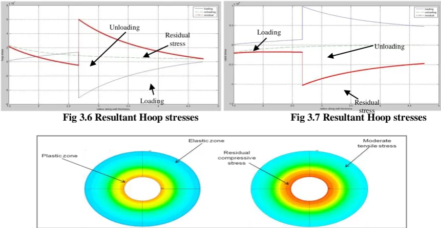
Fig 3.6 Resultant Hoop stresses Fig 3.7 Resultant Hoop stresses
Fig 3.8 (a) Elastic and plastic zone developed during Autofrettage (b) Residual stresses established after Autofrettage
Fig 3.9 Stress distribution in a thick walled cylinder after Autofrettage
IV. MAXIMUM AND MINIMUM AUTOFRETTAGE PRESSURES
The minimum Autofrettage pressure, Py1, is the pressure at which the inner radius of the cylinder, r = a, starts yielding. While at maximum Autofrettage pressure, Py2, the outer surface, r = b, yields. According to Xiaonying and Gnagling [17] and based on von Mises yield criteria, these two pressures are determined as follows [16]
Substituting, we have the Py1= 166.053 MPa; Py2 = 308.91 MPa
𝝈𝒓𝒆𝒔 𝒉𝒐𝒐𝒑= 𝝈𝜽𝒖𝒏𝒍𝒐𝒂𝒅𝒊𝒏𝒈− 𝝈𝜽𝒍𝒐𝒂𝒅𝒊𝒏𝒈
𝝈𝒓𝒆𝒔 𝒓𝒂𝒅𝒊𝒂𝒍= 𝝈𝒓 𝒖𝒏𝒍𝒐𝒂𝒅𝒊𝒏𝒈− 𝝈𝒓 𝒍𝒐𝒂𝒅𝒊𝒏𝒈
Residual stress
Unloading Loading
Loading Residual
stress
...4.1
𝑷𝒚𝟐𝑽𝑴=
𝟐 𝟑∗ 𝝈𝒚
𝐜𝐨𝐬 𝝅𝟐+𝝋𝒏
𝐜𝐨𝐬 𝝋𝒂+𝝋𝒏 (𝟑𝒏𝟐+𝒏) 𝟑𝒏𝟐+𝟏
𝒆
𝟑𝒏 𝒏+𝟏 𝟑𝒏𝟐+𝟏 𝝋𝒂−
𝝅
𝟐 𝒄𝒐𝒔𝝋𝒂 ...4.2
Another theoretical approach to determine the maximum and minimum autofrettage pressure is by the Tresca criteria [16] and is given by,
Substituting, we have the Py1= 163.80 MPa; Py2 = 249.136 MPa
The two above sets of calculated pressures are then compared to the numerical results from FEA analysis. It is predictable that the von Mises yield criteria give accurate since it considers the plastic behavior of the material i.e. σ-ε is taken into account. Hence form the calculation the autofrettage pressure should be within the range of 166.05 and 308.91MPa. Also should be more than the operating pressure 180bar. Hence we consider 200MPa as the autofrettage pressure for our study.
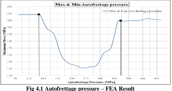
Fig 4.1 Autofrettage pressure – FEA Result
In this study the working pressure of 180MPa and autofrettage pressure is varied from 70MPa to 440MPa. A plot of maximum stresses for various Autofrettage pressures is plotted as shown in the figure 4.1. Table 4.1 concludes the achieved minimum and maximum of autofrettage pressures using different approaches.
Table 4.1 Minimum and maximum Autofrettage pressure
Pressure [MPa] Approach
von Mises yield Criteria Tresca yield Criteria FEA Analysis Minimum Autofrettage pressure Py1 166.05 163.80 138.4
Maximum Autofrettage pressure Py2 308.91 249.136 366.5
V. RESULTS AND DISCUSSIONS
5.1 COMPARISON OF NON- AUTOFRETTAGED AND AUTOFRETTAGED CYLINDER
The analysis has been done considering an operating working pressure of 180bar and an autofrettage pressure of 200MPa. To understand the benefit of Autofrettage process, a comparison is done between a Non-Autofrettaged cylinder and an Non-Autofrettaged cylinder. Von-Mises stress levels of both the cylinder are analysed and the results are as shown in the figure 5.1. Purple contour in the contour plot indicates that the stress value exceeds 230MPa (maximum) for a Non-Autofrettaged cylinder whereas the stress levels in an Autofrettage cylinder are well below 230MPa (red contour). This shows the reduction in the von Mises stresses.
Fig 5.1 (a) Non- Autofrettaged cylinder (b) Autofrettaged cylinder ………...4.3
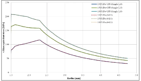
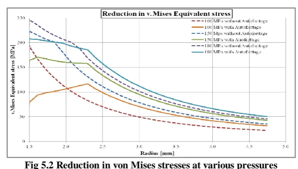
Fig 5.2 Reduction in von Mises stresses at various pressures
The reduction in the stresses can be seen from the figure 5.2 at 100, 150 and 180MPa respectively. A percentage reduction of 15.72% is observed at 180Mpa, 25.67% at 150Mpa and 59.12% at 100Mpa.
5.2 POSITION OF MAXIMUM OF VON MISES STRESSES AND RADIUS OF PLASTICITY
Figure 5.3 shows the position of maximum von Mises stress when the working pressure is 180MPa and for different Autofrettage pressures.
Fig 5.3 Position of maximum of von Mises stresses
The graph clearly indicates the location on maximum stress (von Mises). For an autofrettage pressure between 70MPa to 130MPa, the maximum stresses occur at a radius of 1.5mm. But as the Autofrettage pressure increases, the location of maximum stresses moves towards the outer radius. It can be observed that, at 200MPa (Autofrettage pressure) the maximum stressed region occurs at a radius of 2.38mm. In other words, for an Autofrettage pressure of 200MPa, the cylinder walls yield (plastically) up to2.38mm. This radius is known as the “Radius of Plasticity”. Above certain Autofrettage pressure, the walls of the cylinder undergo permanent plastic deformation.
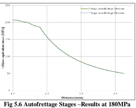
5.3 EFFECT OF AUTOFRETTAGE STAGES
A cylinder is considered with working/operating pressure of 180MPa and autofrettage pressure of 200 MPa. At first step the autofrettage is done in three loading stages and in the second step autofrettage is done in seven loading stages.
Fig 5.6 Autofrettage Stages –Results at 180MPa
From the numerical simulation, it is remarked that in both cases the von Mises stress is 246.59 MPa and the stress pattern is almost similar. So there is no effect of loading stages on autofrettage process. This can be observed from the overlapping curves as shown in figure 5.6
VI. CONCLUSION
Autofrettage of a cylinder made of strain hardening material based on the von-Mises yield criterion has been studied theoretically and numerically (ANSYS) and corresponding equations for optimum autofrettage pressure have been used to determine the minimum and maximum Autofrettage pressures. The process has also been simulated by a commercial finite-element code. It has also been proved that the
residual stresses are carried forward to all the load steps when simulated in ANSYS (FEA). The results of FEA are in good agreement with those of the theoretical analysis.
The position of the maximum of von Mises stress for various autofrettage pressures have been analysed and found that stresses are maximum at an Autofrettage pressure of 350MPa. The beneficial effect of Autofrettage has been proved by the reduction in the von Mises Stresses by 15.72%.
Autofrettage process has no effect on the number of stages.
Autofrettage process does not affect the dimensions of the component.
This simulation approach can be followed for the analysis of any application such as automobile components, boilers design and high pressure components.
VII. APPENDIX
Table 6.1 Nomenclatures
Symbol Meaning Unit
σr Radial stress MPa
σθ Hoop stress MPa
σz Axial stress MPa
σy Yield stress MPa
Pi Internal Pressure MPa
Py1 Minimum Autofrettage pressure MPa Py2 Minimum Autofrettage pressure MPa
ri Inner radius mm
ro Outer radius mm
a Autofrettage radius mm
r Radius mm
K Radius ratio ---- [mm/mm]
REFERENCES
Journal Papers:
[1] Davidson, T.E. and Kendall, D.P, 1970, "The design of pressure vessels for very high pressure operation", Mechanical Behavior of Materials under Pressure, (H.L.P. Pugh, Ed.), Elsevier Co.
[3] Perl, M., 2000, "The change in overstrain level resulting from machining of autofrettaged thick-walled cylinder", Journal of Pressure Vessel Technology, Vol. 122, No.1, pp.9-14
[4] Perl. M., 1998,"An improved split-ring method for measuring the level of autofrettage in thick-walled cylinders", Journal of Pressure Vessel Technology, Vol. 120, pp. 69-73.
[5] Perl. M., Alperowitz, D., 1997, "The effect of crack length unevenness on stress intensity factors due to autofrettage in thick-walled cylinders", Journal of Pressure Vessel Technology, Vol. 119 , pp. 274-8. [6] Segall, A.E., Tricou, C., Evanko, M., & J.C. Conway Jr. 1998, "Localized autofrettage as a design tool
for the fatigue improvement of cross-bored cylinders", Journal of Pressure Vessel Technology, Vol. 122, No 4, pp.393-7.
[7] pressurized autofrettage thick-walled cylinder-part I: semi-circular and arc erosions", Journal of Pressure Vessel Technology, Vol. 122, No. 4, pp.349- 53.
[8] Parker, A. P., Underwood, J.H., 1996, "Stress intensity, stress concentration, and fatigue crack growth along evacuator holes of pressurized, autofrettaged tubes", Journal of Pressure Vessel Technology, Vol. 118, pp. 336-42.
[9] Badr, E. A., Sorem, J.R., Jr., and Tipton, S. M., 2000, "Evaluation of the autofrettage effect on fatigue lives of steel blocks with cross-bores using a statistical and a strain-based method", Journal of Testing and Evaluation, Vol. 28, No. 3, pp.181-8.
[10] Badr, E. A., Sorem, J.R., Jr., and Tipton, S. M., 1999, "Residual stress estimation in cross-bores with Bauschinger effect inclusion using FEM and strain energy density", Journal of Pressure Vessel Technology, Vol. 121, No. 4, pp.358-63.
[11] Jahed, H., Dubey, R.N., 1997, "An Axisymmetric Method of Elastic-Plastic Analysis Capable of Predicting Residual Stress Field", Journal of Pressure Vessel Technology, Vol. 119, pp. 264-73.
[12] Hassan Fahmy El Shalakany, 1975, “Autofrettage of thick-walled tubesbarrels by the pressure of powder gas”, Research Work, Antonin Zapotocky Military Academy
[13] Lin. Autofrettage of thick cylinders. Int J Pressure Vessel Piping 1998; 75:443–6.
[14] Gao XL. Elasto-plastic analysis of an internally pressurized thick walled cylinder using a strain gradient plasticity theory. Int J Pressure Vessel Piping 2003;40:6445–55.
Books:
[15] Harvey, J.F., (1987), Theory and design of pressure vessels, CSB Publishers & Distributors Pvt. Ltd. [16] Benham, P.P., Crawford, R.J. and Armstrong, C.G., (1996), Mechanics of engineering materials, 2nd
edition, Longman Group Limited. Proceeding Papers: