Abstract—The different welding of dissimilar material combinations such as Al 6061 – Al 6063 is very important. As some of these weld combinations are used in very critical applications such as aerospace, nuclear power plants, cryogenics, rocket fuel systems, electrical and automotive applications. Therefore, the weld strength and its interface properties are extremely important. The failure of these parts can lead to huge losses. The TIG, MIG, ARC, FSW welding of these dissimilar materials is more complicated compared to similar materials due to differences in physical, mechanical, chemical and thermal properties. The recent works metal joining process will be very challenging in this process in dissimilar states. The research fully concentrated on dissimilar joining process in two different alloyed grated materials in this causes AL 6061, and AL6063 respectively. This application of the FSW process is joining process considering in different speed and feed optimization of this study of works will be compared with numerically analyses in this functionally predetermined to inspect values and determine values optioned from the experimentation of this works. This advanced system analyses in this COMSOL 4.5 promises in melting zone and destruction of works
Keywords: Dissimilar material, Optimization, Different Welding, FEA COMSOL 4.3 B
I.INTRODUCTION
Different welding [TIG, MIG, ARC ,FSW] is a
complicated process, which involves interaction of thermal, mechanical and metallurgical phenomenon. It is solid state joining process that produces coalescence in materials, using the heat developed between surfaces through a combination of mechanical induced rubbing motion and applied load. The resulting joint is of forged
Quality. Under normal conditions, the faying surfaces do not melt. Filler metal, flux and shielding gas are not required with this process as refer figure
Fig.1 TIG Welding Process
Volume-6 Issue-1
International Journal of Intellectual Advancements
and Research in Engineering Computations
Experimental analysis and simulation of thermal field
dispersal during welding of dissimilar material
S.Muruganantham
1, M.Srimilan
2, A.S.Dineshkumar
2, R.Gobinath
2, P.Jagankumar
2,
1
Assistant Professor,
2UG Students
Department of Mechanical Engineering, Nandha Engineering College, Erode-52,
Tamil Nadu, India
1
[email protected],
2[email protected]
Fig.2 MIG Welding Process
Fig.3 ARC Welding Process
Fig.4 a) Top holding on side b) Rotation of this path c) plug in seated d) end of path tool.
The TIG/MIG/ARC/FSW welding of dissimilar material combinations such as aluminum and its AL6015 to other graded material and copper are used for critical applications therefore weld strength is extremely important. The failure of weld joint leads to huge losses. Therefore weld quality cannot be compromise.
II. LITERATURE REVIEW
The first successful application of this process is welding of metals which were reported from Russia in 1956. Earlier this process has been used for joining thermos engineering works. In this process one of the pieces to be welded is rotated and the other is made to rub the first one under the axial load resulting in increased TIG/MIG/ARC which helps in heat generation and joining of the two pieces when the pieces are subjected to rest under an enhanced axial load, the joint made by this TIG/MIG/ARC welding method is similar to the ones produced by electrical resistance butt welding process of flash and upset welding.
The efficient and emission less metal joining process is most used in numerous application in boiler industries and shipbuilding industries.
[1] Ali GURSEL. “Ultrasonic welding of dissimilar materials” 2015. Ultrasonic welding has
become significant attention regarding its suitable applications in comparison to traditional welding techniques.
[2] A.H.Kheireddine “Thermo mechanical frictions stir welding in carbon steels”2013. Steel and other high temperature materials, the applications of FSW. (Carbon Steel)
[3] FarzeeShahid “Mechanical and microstructure analysis of dissimilar metal welds”2015.Welding of dissimilar metals involves different types of metals with distinct chemical composition.
[4] JagdeepSangwan “Research paper on temperature modeling of friction welding of Al and Stainless steel”2014 . Two pieces rotated in contact and heat necessary for welding is generated on friction plane.
[5] J.Martikainen , “ Dissimilar high strength steels fusion welding joints” 2016 . The demand for materials with a good ratio of high strength and light weight has arisen from new challenges.
III. PROBLEM IDENTIFICATION
Aluminium alloys are lightweight, have relatively high strength, retain good
ductility at subzero temperatures,
have high resistance to corrosion, and are non-toxic.
They have a melting range between 4820C and 6600C, depending upon the alloy.
It is impossible in practice to stop the tenacious oxide film formed due to oxidation at exposed surfaces.
The major defects FSW process
The commonly described in this associated FSW joints in tunnel hole and worm hole and flash and kissing bond effectiveness basis is to determine this defects of FSW process.
Tunnel hole
This effect should be plasticized metal under the shoulder and cannot flow of heat generation of unsaturated heat of this moment to takes plays .this straight cylindrical and taper cylindrical pin bonding process.
Worm hole Effect
considering in this FSW process should be fluid and flow process in rotating on this cylinder and conditionally effects on normally impacting formation of worm hole effects on per revolution of this time . Large mass of flash (shear lips)
This process should be results of inadequate the highly transport in this weld metal around in this reheating in this pin and plug associated in this materials employed in this plate .the swept and volume is transported in the retreating side of excess in expelled for the weld in entire region.
Kissing Bond.
The associated mono surfaces to take is joined in this kissing bonded which is developed in this mechanism of this insufficient breakup of oxide layer in this contacting surface of this welded pin.
IV.RESEARCH WORK PROCESS
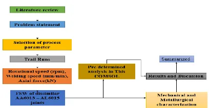
Fig. 5 Research working process
The Dissimilar process to be welded work pieces in Square mating process are clamped on a fixture of entire ends. The setup of prevention basis and spreading in apart from this welding process in this welding too and shank and pin and rotated as described in basic welding procedure responsive. The tool is considered in slowly and plunged into the work piece constructed focused in butt line of joint this joint contribution fully ASTM stands form follows. The tool is gradually plugged in this work piece material in this butt line process and tool forcibly from the back plate of specimen . A downward force is applied to maintain in this contact region in particular thermal field for pre determined heating and softening of this solution and along this short dwell time is observed to allow the development of the thermal field and preheating and softening materials along the joining line. The point a axial forces is applied in the direction perpendicular to welding to traveled in this direction in path. The tool is forcibility traversed along the butt path is welded in start to end of the weld as response alternatively and
this piece of works can be moved in this still being its rooted in this path of moments. FSW is used to control properties in structural metals including in this aluminum and the other nonferrous alloys .The pin and diameter is constructed modeled in one -third of this cylindrical tool shoulder on this path.
V.MATERIALS AND METHODS
The generation of heat and plastic deformation and near pin path parameter functions is adjusted in this frictional to volumetric deformation of induced thermal process of work piece of thicker and heating of deformation is adjusted in frictional to volumetric coefficient materials induced in thermal bonding in heating process. This is in order to ensure the most sufficient and unit length of highly interpretation of unit length. The microstructures of a friction stir weld depends upon this tool and design and this rotation of transverse load determined in this semi automatic friction stir is welded. The Heat effected Zone with respective of flow region and deformed at the entire stage. The details is microstructure may ensure a frequently and dynamically in this process and detailed and microstructure may considered in this equated grains. This specific of this region of this passage of structure is consequence of the way in this threaded tool deposits materials form and the back of the weld of this part. The simple services of the rotation of the tool and welded and characterization of this regions and quality depends on this tool rotation and applies more forces and pressure. The material characterization and tool depth and profile.
Table. 1 Mechanical and physical properties of Al
6061-6063 alloy
material in welded joint. The shoulder is generated in most of the heat and prevents the plasticized material and flow of this recent of years and new features and introduced in this design of tools . The Whorl and MX-Triflute have simple pin and tool modeled in this geometry constructed in cylindrical pin. The tapered in this threads and whorl design and vertical component of velocity and tool and work piece of heat generative of flow of dissimilar material process.
Fig.6 Al 6061-6063 alloy Composition material
VI.MATERIAL DIMENSION
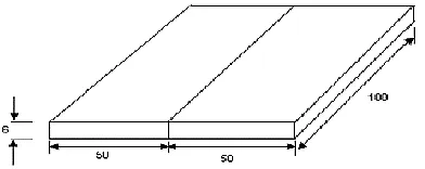
This research modeled in 6mm Thickness is applied in dissimilar material alloy in This AL6061 ,Al6063 material is taken in to cut and manual cutting in ASTM standards flows to take grinding this as shown in figure 6.1 this simulation analysis .This FSW joints is initially obtained in this consumable and non consumable of this welding sources .This highly carried in tool dimension fixture safety process basis is found at exterior of this works is found it. the exterior welded on this surface of free joints and defects on free and feasible limits is chosen in this parameters of this function .
Fig. 7 Geometry model in work piece
With regular joint geometry. It was observed that the weld strength of new joint geometry was more than the regular joint geometry.
The ultimate tensile strength with new joint geometry for Al 6061to AL 6063 was 278.56 MPa whereas for regular joint geometry it was 254 MPa Similar trend was observed in weld combinations of Al 6061 to AL 6063, Pure Al pure Al to copper.
VII.METHODOLOGY
The past scientific paper faced on this FEA packages solve in ANSYS only analysis it .This is solver in the current research of works considered in this geometry of present research. The geometry is assigned a boundary conditions of well developed in this model in FSW .The Concept is fully super system analysis in this COMSOL 4.2b software is used to determine a process as shown in figure 7
Fig. 8 work flows
This process will be undergoing orthogonal material only and it is determined in this predevelopment process applied in 3Dimensional process .This is steady state function of transient thermal analysis in this element also can be a mass transfer of this experimental and numerical analysis in this fields .The parametric dimensions actions of friction heating simulated in this shoulder plate interface the forging effect created in this drive of the pin among two tightly held on this entire plates. The primary works in approximation and work will be computational constraints of works and special FSW process is generative modeled in 3Dimensional issued in this plates. As the pin is rigid and this work pieces will be devised in the common holder process .This simulation process is thermo mechanical cause study only take it. This predetermined in order of
% by wt. , Al, 98.6,
96% % by wt. , Cu, 0.4,
1% % by wt.
, Cr, 0.35, 0% % by wt. , Fe, 0.7,
1% % by wt. , Mg, 1.2,
1% % by wt.
, Mn, 0.15, 0% % by wt. , Si, 0.8,
1% % by wt. , Ti, 0.15,
0% % by wt.
, Zn, 0.25, 0%
approximation of this measured in temperature in standards in definite solid mechanics and models applied in FSW process.
Analysis of Comsol Multiphysics
A computational method is a traditional approach for robust experimental design that seeks to obtain the best combination set of factors/levels with the lowest societal cost solution to achieve customer requirements. The experimental results are analyzed using Comsol Multiphase’s for identifying the significant parameters affecting the performance measurers on the total variance of the results.
In the Comsol design method the design parameters and noise factors, which influence product quality, are considered. Comsol method is applied for solving single response optimization problem with the objective of minimization of W, R maximization of P and Ts. The experimental results and S/N ratio for the quality of the different weld condition for AISI304.as refer this basic modeling geometry.
Fig.9 Basic model geometry in COMSOL
Simulation analysis of shielded metal ARC /MIG/TIG/FSW welding process
The experimental run ratio for the weld bead is given in the data is imported from a file into COMSOL. COMSOL is also used to interpolate the data when the values of k and cup are varied. Only part of this data has been considered. Values near and above the fusion temperature and solid phase transformations
have been neglected. The following equation describes heat transfer in the plate.
Fig 10 Boundary conditions
SMAW/TIG/MIG/FSW welding process
As a result of fixing the coordinate system in the welding tool, the equation includes a convective term in addition to the conductive term. The equation is applied boundary conditions as representing figure 6.The data are presented in linear interpolation is utilized. Outside of the domain of temperatures covered in the values for k and Cp are assumed to be constant with respect of level factors. Where k represents thermal conductivity, ρ is the density, Cp denotes specific heat capacity, and u is the velocity. The model sets the velocity to u = 1.59 X 10⁻³ m/s in the negative x direction.
VIII. RESULT AND DISCUSSION
The weld quality of new joint geometry is contrasted and general joint geometry. It was watched that the weld quality of new joint geometry was more than the general joint geometry. A definitive rigidity with new joint geometry for Al 6061to AL 6063 was 278.56 MPa while for consistent joint geometry it was 254 MPa. Comparable pattern was seen in weld mixes of Al 6061 to AL 6063, Pure Al unadulterated Al to copper.
In new joint geometry the material utilization was not as much as general joint geometry. It helps in material cost sparing by 46 % to 56% when contrasted with consistent joint geometry.
uniform weld quality along the bond line which was a noteworthy issue in the normal joint geometry. Customary joint geometry does not give the uniform weld quality, weld quality is less in internal district (focus parcel) when contrasted with external locale due to unbound area, entanglement of oxides and different pollutions in the inward district.
IX. CONCLUSION
In this exploration, the TIG/MIG/ARC welding process was enhanced by turning around the movement of welding by outlining another joint geometry. In new joint geometry welding is started from the inward district and it advances to external locale. The state of new joint geometry helps in uniform warmth age at the weld interface and it encourages in demolition and expulsion of oxides and different defilements from the inward area of weld interface. The uniform temperature, expulsion of oxide layer, and movement of welding from inward to external area, helped in keeping the development of unbound zone at the internal district of the weld interface which brings about better weld quality.
REFERENCES
[1] Ali Gursel. “Ultrasonic welding of dissimilar materials”, Journal of material science and technology, 2015, Vol.43, pp.290-304.
[2] A.H.Kheireddine “Thermo mechanical friction stir welding in carbon steels” International Journal of Fatigue, 2013 ,Vol.15, pp.152-163.
[3] FarzeeShahid “Mechanical and micro structural analysis of dissimilar metal welds” International
Journal of Research in Engineering and
Technology, 2015, Vol.26, pp.1058-1063.
[4] JagdeepSangwan “Research paper on temperature modeling of friction welding of Al and Stainless steel” Journal of material science and technology, 2014, Vol.45, pp.85-92.
[5] J. .Martikainen , “Dissimilar high strength steels fusion welding joints” ” International Journal of Research in Engineering and Technology, 2016,
Vol.79,pp.46-53 .
[6] M.SathyaNarayana Gupta “Thermo mechanical Analysis of friction stir welded Al/ Cu”, International Journal of Fatigue, 2012 , Vol.28, pp. 279-288.
[7] Dr.Rajendra “Thermo mechanical analyse in Tig welding”, International Journal of Research in Engineering and Technology , 2013, Vol.62, pp.427-433.