11 |
P a g e
DESIGN OF SUBSTATION GROUNDING IN A TWO
LAYER EARTH STRUCTURE
(A CASE STUDY OF 132KV SUBSTATION)
Prakash K Makhijani
1, Chirag J Soni
2, Riya B Agarwal
3 1Director,
2Design Engineer,
3Design Engineer, Ohm Encon Pvt. Ltd,(India)
ABSTRACT
Earth mat provides a common ground for the electrical equipment as well all the metallic structures in the substation. The personnel safety and protection of equipment depends solely upon the effective Grounding system and hence its design becomes a critical aspect in substation. When there is an Earth Fault, it gives rise to potential gradient (GPR) within and around the substation. This GPR has to be restricted to a value which is not detrimental to the surrounding personnel and equipment. The GPR depends on various factors, one of which is the type of soil in substation. In this paper, design of the grounding grid for rectangular configuration is done for a 2 layer soil and analysis is done by ETAP software. The methodology adopted for designing is based on IEEE Std. 80-2013.
Keywords : Earthing / Grounding, Earth mat, Electrode, ETAP, Ground Resistance, Step Potential, Touch
Potentia, Ground Potential Rise.
I. INTRODUCTION
For the uniform and continuous soil models, simple algorithms can be developed to analyze the effectiveness of
earthing system. However, where there is a significant variation in the resistivity with respect to depth,
Multilayer soil models may also be adopted. The simplest is a 2 layer model, which can be a good
approximation for analysis purpose. Another aspect which makes the design critical is the unequal spacing in the
earth mat. It is always desirable to use computer software to design and analyze the grounding mesh using
multilayer soil models and earth mats with varying spacing. One of the best software for this purpose is
ELECTRICAL TRANSIENT ANALYZER PROGRAM (ETAP).
ETAP facilitates an engineer to carry out ground grid design as well as analysis with considerations specified in
various standards such as IEEE-80-1986, IEEE-80-2000 and IEEE-665-1995. Moreover, this software also
provides finite element modeling (FEM) of the ground grid for an accurate analysis. Both aspects, technical and
commercial can be very well taken care using this software.
II.
SOIL RESISTIVITY AND IT’S MEASUREMENT
The resistance of an earth electrode is mainly influenced by the resistivity of the soil in which it is driven.
Hence, the soil resistivity measurement is an important aspect and its accurate measurement ensures a perfect
design. Apart from knowledge of the soil resistivity at the project site, it is also important to understand the
behavior of soil with be economically accomplished and retained over the life time of the earthing installation.
There are basically 2 types of earths. One is the system earth and the other is the equipment earth. The idea of
12 |
P a g e
instruments, raceways and plant structure and building. To achieve this objective, a suitable low resistanceconnection to ground is desirable. However, many a times this is difficult to achieve as it depends on a various
factors:
Soil resistivity and soil stratification Size and type of electrode used
Depth to which the electrode is driven or buried Moisture and chemical content of the soil Area of substation
Fault current being handled
The purpose of resistivity testing is to obtain a set of measurements which may be used to derive an equivalent
model of earth system seen by the electrical system.
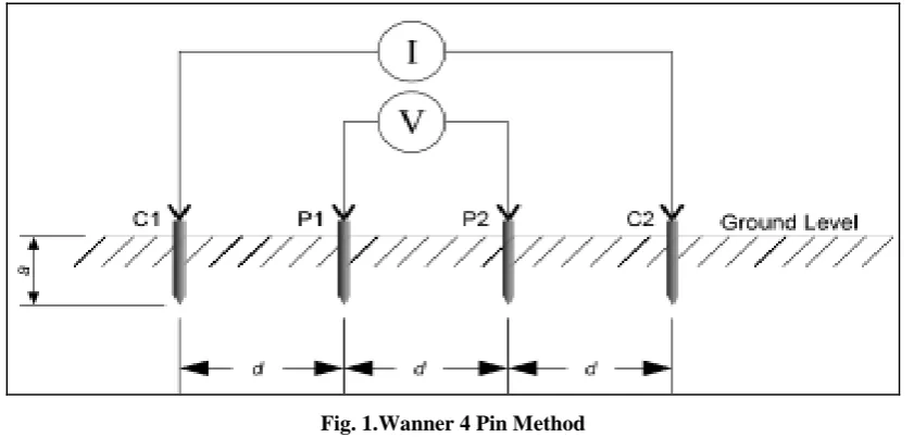
Wanner 4 Pin Method
The Wenner array method has certain limitations such as requirement of longest cable layout, largest electrode
spreads and for large spacings one person per electrode is necessary to complete the survey in a reasonable time.
Also, because all four electrodes are moved after each reading the Wenner Array is most susceptible to lateral
variation effects.
Fig. 1.Wanner 4 Pin Method
However the Wenner array is the most efficient in terms of the ratio of received voltage per unit of transmitted
current. Where unfavorable conditions such as very dry or frozen soil exist, considerable time may be spent
trying to improve the contact resistance between the electrode and the soil.
III.
EASE
OF
CALCULATION
FOR
STEP
AND
TOUCH
POTENTIAL
USING
ETAP
In normal practice for earthing design and analysis we use the ETAP software just to calculate the step and
touch potentials, as their calculations are tedious and time consuming. We can design an earthing grid and place
the earth electrodes using ETAP. It can also optimize the use of electrodes considering the cost in concern. We
can obtain the 3-D graphs for the step and touch potentials. There are basically two methods available for the
step and touch potential calculations. They are finite element method (FEM) and IEEE method. We can choose
13 |
P a g e
compared to IEEE in designing the shape of the grid. If we choose FEM method then can model any shape ofgrid as per the plan dimensions while in case of IEEE method some specific shapes are given. We cannot design
any complex shape of grid in IEEE method. So it is better if we choose FEM method.
One more important consideration is the type of soil considered. In ETAP we can choose different layers of soil.
In international standards for earthing system design generally multiple layers of soil are considered. The top
most layers will have more resistivity than the deeper layers. Top most level generally consists of gravels which
have higher resistivity. In ETAP the approximate values of resistivity of different layers are given and they can
be edited if required.
IV.
SAFETY
CRITERIA
FOR
SUBSTATION
GROUNDING
DESIGN
AS
PER
IEEE
S
TD.
802000
A person working in substation may be subjected to five shock situations namely, Step voltage, Touch voltage,
Mesh voltage, Metal to metal touch voltage and Transferred voltage. Step and Touch voltage are used to derive
the safety criteria for Grounding grid design. A good grounding system should have the actual mesh and step
voltages well below tolerable touch and step voltages respectively. Fibrillation discharge limit of body current
is used to determine the tolerable safety criteria for grounding system design. The main consideration that is
taken into account for substation grounding design is that under any circumstance actual step and mesh voltages
must not exceed the tolerable Voltage limits.
V.
TWO
LAYER
SOIL
MODEL
BY
SUNDE’S
GRAPHICAL
METHOD
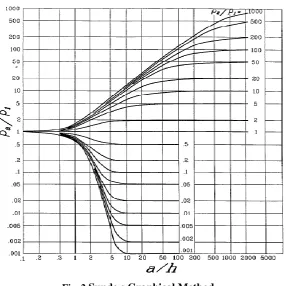
In Sunde‟s method, the graph shown in Figure 2 is used to approximate a two-layer soil model.
Parameters ρ1 and ρ2 are obtained by inspection of resistivity measurements. Only h is obtained by Sunde‟s
graphical method, as follows:
Step 1: Plot a graph of apparent resistivity ρa on y-axis vs. pin spacing on x-axis.
Step 2: Estimate ρ1 and ρ2 from the graph plotted in step 1.ρacorresponding to a smaller spacing is ρ1 and for a larger spacing is ρ2. Extend the apparent resistivity graph at both ends to obtain these extreme
resistivity values if the field data are insufficient.
Step 3: Determine ρ2/ρ1 and select a curve on the Sunde graph in Figure 2, which matches closely, or
14 |
P a g e
Fig. 2.Sunde,s Graphical Method
Step 4: Select the value on the y-axis of ρa /ρ1 within the sloped region of the appropriate ρ2/ρ1 curve of
Figure 2.
Step 5: Read the corresponding value of a/h on the x-axis.
Step 6: Compute ρaby multiplying the selected value, ρa /ρ1, in step 4 by ρ1.
Step 7: Read the corresponding probe spacing from the apparent resistivity graph plotted in step 1. Step 8: Compute h, the depth of the upper level, using the appropriate probe separation.
VI.
MATHEMATICAL
CALCULATION
A.Prerequisites
The following information is required / desirable before starting the calculation:
A layout of the site.
Maximum earth fault current into the earthing grid. Maximum fault clearing time.
Ambient (or soil) temperature at the site.
Soil resistivity measurements at the site (for touch and step only).
Resistivity of any surface layers intended to be laid (for touch and step only).
B.
Step and touch voltage criteria
The safety of a person depends on preventing the critical amount of shock energy from being absorbed before
the fault is cleared and the system de-energized. The maximum driving voltage of any accidental circuit should
not exceed the limits defined as follows.
15 |
P a g e
𝐸𝑆𝑡𝑒𝑝 = [1000 + (6 ×𝐶𝑠× )] (1) The tolerable touch voltage criteria is
𝐸Touch=[1000 + (1.5 × 𝐶𝑠 × 𝜌𝑠 )]
(2)
Where,
Estep = the step voltage in V
Etouch = the touch voltage in V
Cs= 1for no protective layer
ρs = the resistivity of the surface material in Ω·m
ts = the duration of shock current in seconds
The earth grid conductor size formula is mentioned below
I=A (3)
Where,
I = rms value in kA
A = conductor sectional size in mm²
Tm = maximum allowable temperature in °C
Ta = ambient temperature for material constants in°C
a0 =thermal coefficient of resistivity at 0°C
aᵣ = thermal coefficient of resistivity at reference temperature Tr
ρᵣ = the resistivity of the ground conductor at reference temperature Tr in uA/cm3
K˳ = 1/ a0 or 1/ a0 - Tr
tc = time of current flow in sec
TCAP = thermal capacity factor
Spacing factor for mesh voltage (Km)
(4)
Where,
D = spacing between conductor of the grid in m
d = diameter of grid conductor in m
KM = spacing factor for mesh voltage
Kii = 1 for grids with rods along perimeter
Kh = Corrective weighting factor for grid depth
Spacing factor of step voltage (Ks)
(5)
Where,
D = spacing between conductor of the grid in m
h = depth of burial grid conductor in m
16 |
P a g e
Evaluation of ground resistanceA good grounding system provides a low resistance to remote earth in order to minimize the GPR. For most
transmission and other large substations, the ground resistance is usually about 1 Ωor less. In smaller
distribution substations, the usually acceptable range is from 1 Ω to 5 Ω, depending on the local conditions. For
calculation of grounding resistance, the following formula is used
(6)
Where,
ρ = soil resistivity Om
LT = total length of grid conductor m
A = total area enclosed by earth grid m2
h = depth of earth grid conductor m
For calculation of grid current, equation
𝐼𝐺=(𝐶𝑃× 𝐷𝑓× 𝑆𝑓 × 𝐼)
(7)
For calculation of grid potential rise
𝐺𝑃𝑅
=(
𝐼𝐺
×
𝑅
g)
(8)
Actual Step Potential & Touch Potential Calculations
Formula for calculation of mesh voltage is
(9)
Formula for calculation of step voltage is
(10)
𝐿𝑇 =(𝐿𝐿 + 𝐿𝐵 + 𝐿𝐴 + 𝐿𝐸)
(11)
Where,
ρ = soil resistivity, ohms-m
Em = mesh voltage at the center of corner mesh in V
Es = step voltage between point in V
Km = spacing factor for mesh voltage
Kis = spacing factor of step voltage
Kim = correct factor for grid geometry
LL= Length of grid conductor along length of switch yard
LB= Length of grid conductor along breadth of switch yard
LA= Length of riser and auxiliary mat in switch yard
LE= Length of earth electrodes in switch yard
17 |
P a g e
VII.
RESULTS
A real time project is considered for this case study and a ETAP modeling is developed to carry out the earth
mat design. This project has 132 KV GIS substation and 66/11 KV AIS substations. Earth mat is proposed for
GIS as well as for AIS substations. Soil resistivity tests were conducted at project site area and same data was
used for doing design calculations. Soil resistivity is the key factor which determines the resistance or
performance of an electrical grounding system. Based on the soil data, 2 layer model is derived using Sunde‟s
Graphical Method. Below are the input data details.
Surface layer resistivity : 10,000 ohm-m
Depth of Surface Material : 0.12 m
Soil Model : 2 Layer
Top layer resistivity : 30.15 ohm-m
Depth of Top layer : 1.96 m
Lower layer resistivity : 2.49 ohm-m
Conductor & Rod type : MS
Fault Current : 40kA
Duration of Fault Current : 3 Sec
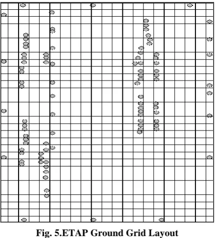
Based on site area, we decided to choose rectangular grid pattern (different grid patterns are available-L shape,
T-shape) and spacing between conductors is 3 meters. Grid is buried at a depth of 0.6m. The configuration of
the grid is shown in the below Figure 5. As per the calculations required number of conductors is 54 and the
rods are 98. It is found that both manual and simulated values are satisfactory. Figure 6 shows 2 layer soil model
in ETAP and Figure 7 shows ground grid layout in ETAP.
Fig. 3.ETAP Ground Grid Model
18 |
P a g e
Fig. 5.ETAP Ground Grid LayoutThe following 3-D Potential profiles are available for analysis of GGS study with the FEM method. Figure 8
shows Absolute potential profile, Figure 9 and 10 shows Touch Potential and Step Potential profile with over
voltage limit.
Fig. 6.Absolute Potential Profile
19 |
P a g e
Fig. 8.Step Potential ProfileVIII.
CONCLUSIONThe results for earthing system are obtained by ETAP software. For earthing conductor and vertical earth
electrode, mild steel is used. Step by step procedure has been considered in the long hand calculations. The step
and touch voltages are dangerous for human body. Human body may get electric shocks from step and touch
voltages. When high voltage substations are to be designed, step and touch voltages should be calculated and the
actual values based on design must be maintained below the tolerable values. Importance is to be given to the
transfer of Ground Potential rise (GPR) under fault conditions to avoid dangerous situations to the personnel and
even the animals in the vicinity of substations. The values of step and mesh voltages obtained for 132 kV
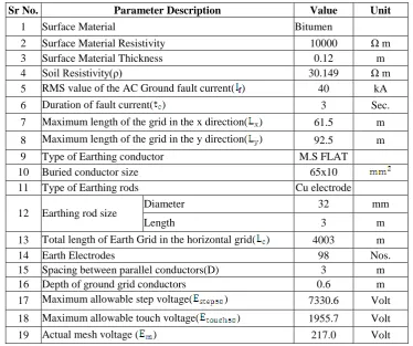
substation are respectively 105.3 Volt and 217.0 Volt which are within the permissible limits. Table 1 shows
summary of earthing grid design.
TABLE I. EARTHING DESIGN SUMMARY
Sr No. Parameter Description Value Unit
1 Surface Material Bitumen
2 Surface Material Resistivity 10000 Ω m
3 Surface Material Thickness 0.12 m
4 Soil Resistivity(ρ) 30.149 Ω m
5 RMS value of the AC Ground fault current( ) 40 kA
6 Duration of fault current( ) 3 Sec.
7 Maximum length of the grid in the x direction( ) 61.5 m
8 Maximum length of the grid in the y direction( ) 92.5 m
9 Type of Earthing conductor M.S FLAT
10 Buried conductor size 65x10
11 Type of Earthing rods Cu electrode
12 Earthing rod size Diameter 32 mm
Length 3 m
13 Total length of Earth Grid in the horizontal grid( ) 4003 m
14 Earth Electrodes 98 Nos.
15 Spacing between parallel conductors(D) 3 m
16 Depth of ground grid conductors 0.6 m
17 Maximum allowable step voltage( ) 7330.6 Volt
18 Maximum allowable touch voltage( ) 1955.7 Volt
20 |
P a g e
20 Actual step voltage ( ) 105.3 Volt
21 Total Resistance of earth grid( ) 0.024 Ω
22 Ground potential rise(GPR) 592.1 Volt
REFERENCES
[1] Ei Ei Cho & Marlar thein Oo “Design of Earthing System for New Substation Project (Shwe Sar Yan) in
myanmar” World Academy of Science , Engineering and Technology 42 -2008
[2] Prof Gaurang K Sharma, Prof. Ashish R.Patel, Prof.Akshay A. Pandya, Dharita Patel “Optimization of
Earthing Gird design for E.H.V.A.C. Substation by user –interactive approach” National Conference on
Reacent Trends in Engineering Technology 13-14 May 2011.
[3] IEEE Recommended Practice for Groudning of Inductrial and Commercial Power Systems., ANSI/IEEE
Standard 142, 1982.
[4] IEEEE Recommended Practice for Powering and Groudning Sensitive Electronic Equipment, ANSI/IEEE
Standard 1100- 1992.
[5] Geri. A, “ Behaviour of grounding system excited by high impulse current: the model and its validation,”
IEEE Trans, Power Deliver, 1999.
[6] Gagg.G.F, Earth Resistances, New York, 1964.
[7] Tarpar.B and Gross.E.T.B, Ground Grid of High Voltage Stations.1963.
[8] IEEE Recommended Practice for Electric Power Distribution for Industrial Plants. IEEE Std 141-1993.
[9] IEEE Guide for Safety in AC Substation Grounding, IEEE 80 -2013.
[10] IEEE Recommended Practice for Industrial and Commercial Power Systems Analysis. IEEE Std 399 –
1997.
[11] M. Nassereddine, J. Rizk, and G. Nasserddine, "Soil Resistivity Data Computations; Single and Two -
Layer Soil Resistivity Structure and Its Implication on Earthing Design", World Academy of Science,
Engineering and Technology, vol. 73, pp. 1043-1048, 2013.
[12] J I. Colominas, F. Navarrina, and M. Casteleiro, "A Numerical Formulation for Grounding Analysis in
Stratified Soils", IEEE Transactions on Power Delivery, vol. 17, no. 2, april 2002.
[13] IEEE, “IEEE Recommended Practice for Determining the Electric Power Station Ground Potential Rise
and Induced Voltage From a Power Fault,” IEEE Std 367-1996, 1996, pp. 1-125
[14] Rao Sunil S., ‗Switchgear Protection and Power Systems„. 12th edition, Khanna Publishers, New Delhi,
2007
[15] Mc Donald John D., ‗Electrical Power Substation Engineering„, CRC Press, 2006.
[16] Puttarach A., Chakpitak N., Kasirawat T. and Pongsriwat C. 2007, Ground layer depth and the effect of