AN EXPERIMENTAL STUDY OF ADDED MASS EFFECTS IN TWO PHASE SOLID/LIQUID MEDIA
A Thesis
submitted for the degree of Doctor of Philosophy
by
Alfred KHODAVERDIAN
Department o f Chemical & Biochemical Engineering University College London
Torrington Place London WCIE
ProQuest Number: 10106507
All rights reserved
INFORMATION TO ALL U SE R S
The quality of this reproduction is d ep en d en t upon the quality of the copy subm itted. In the unlikely even t that the author did not sen d a com plete manuscript
and there are m issing p a g e s, th e se will be noted. Also, if material had to be rem oved, a note will indicate the deletion.
uest.
ProQ uest 10106507
Published by ProQ uest LLC(2016). Copyright of the Dissertation is held by the Author. All rights reserved.
This work is protected against unauthorized copying under Title 17, United S ta tes C ode. Microform Edition © ProQ uest LLC.
ProQ uest LLC
789 East E isenhow er Parkway P.O. Box 1346
ABSTRACT
This thesis describes the results o f a series o f experimental studies in which the added mass and drag experienced by a 25 mm sphere oscillating in a two phase system, consisting o f bonded solid particles in liquid media are measured in a variety o f configurations using a remote drive vibrating reed technique.
The arrangements considered investigate the effects o f surface roughness, proximity and orientation o f neighbouring particles , bed voidage together with variations in fluid density and viscosity , expressed in terms of the Stokes number in the range o f 45-1100.
Three types o f expressions for the subsequent prediction o f added mass are produced.
The first starts with the sim ple notion o f the hydraulic diameter to modify the Stokes theoretical expression for added mass obtained from potential flow analysis to produce an equation for the variation o f the added mass with bed voidage for a smooth sphere in in viscid fluid media. The correlation is then validated by experim ental evidence.
The secon d exp ression is obtained by correlatin g the experim entally measured values o f added mass with bed voidage and surface roughness in inviscid fluid media. The last expression , applicable to smooth particles in viscous media, takes into account the effects o f Stokes number as well as bed voidage.
ACKNOWLEDGEMENTS
I w ish to express my sincere gratitude to Dr Haroun M ahgerefteh for his guidance, encouragement and patience throughout the course o f this work.
I am also very grateful to Professor Larry Gibilaro and Dr Hassan Al-Khoory for many useful discussions and interest in this work, and to Messrs Don Montgomery, Martin Vale and all other technical staff for their support.
(ienius
docs what
it must
Talent does
what it can
!
CONTENTS
ABSTRACT
ACKNOWLEDGEMENTS
CHAPTER 1 INTRODUCTION
CHAPTER 2 LITERATURE SURVEY 1 1
2.1 Mathematical Definition o f Added Mass 1 1 2.2 Stokes Theoretical Formulation o f Added 1 4
Mass for Inviscid and Viscous Fluids o f Infinite Extent
2.3 The Effect o f External Boundaries 2 4
2.4 The Effect o f Reynolds Number and Surface 3 4 Roughness on The Added Mass
2.5 The Effect o f Added Mass on The Stability 4 4 o f Fluidised Beds
2.5.1 Theoretical Consideration o f Fluidised Bed 4 5 Behaviour: Particulate to Aggregate
T ran sition
CHAPTER 3 EXPERIMENTAL 6 3
3.1 A p p aratu s 6 3
3.2 The Electronic Drive and Detection System 6 9 3.3 The Theoretical Prediction o f The Resonant 7 4
Frequency: Optimisation o f The System's R esp on se
3.3.1.1 Optimum Clamping Ratio and Mode o f 79 Operation
3 .3 .1 .2 Optimum Mass Ratio 8 3
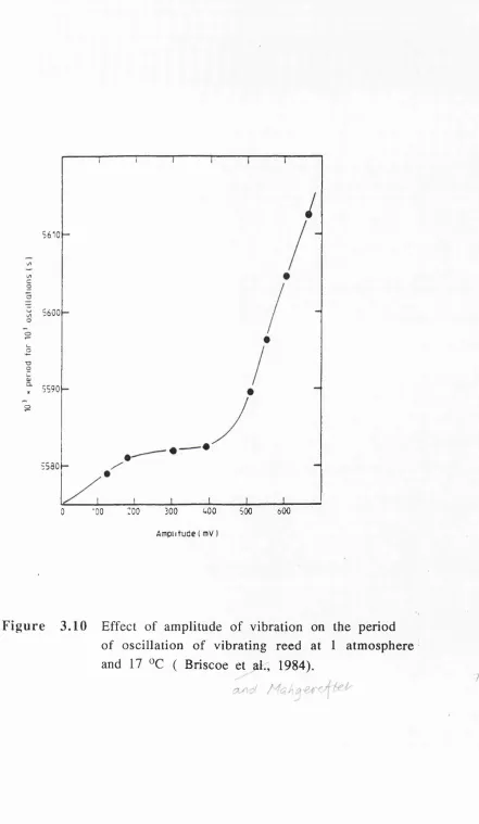
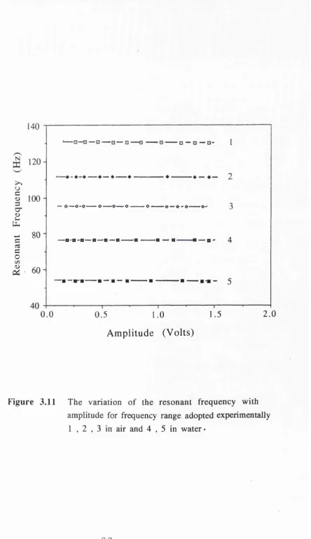
3.3.1.3 Optimum Diameter o f The Attached Sphere 8 6 3.3.1.4 The Effect o f Amplitude o f Vibration on The 86
Resonant Frequency: Softening Spring
Behaviour and Convective Acceleration Effects
3.3.1.5 Wall Effects 9 0
3.4 Calculation Procedure for The Determination 93 o f The Added Mass
CHAPTER 4 RESULTS AND DISCUSSION 10 5
4.1 Two Spheres in Line 1 0 5
4.2 Two Spheres M isaligned 1 1 0
4.3 The Variation o f Added mass Coefficient 1 1 4 with Voidage
4.3.1 Theoretical M odelling and Experimental 1 1 5 Validation o f The Variation o f Added Mass
with Voidage
4.3.2 The Effect o f Fluid Viscosity and Voidage 1 2 6 on The Added Mass Coefficient
4.3.2.1 Smooth Particles 1 3 2
4.3.2.2 Rough Particles 1 4 3
4.3.3 The Effect o f Fluid Density and Voidage on 1 5 2 The Added Mass Coefficient
4.3.3.1 Smooth Particles 1 5 8
4.3.3.2 Rough Particles 1 5 8
4.4 Stability o f Liquid Fluidised Beds: New 166 Estimations o f The Dynamic Wave Velocity
CHAPTER 5 CONCLUSIONS 1 7 5
REFERENCES 1 8 6
APPENDICES
CHAPTER 1
INTRODUCTION
The acceleration o f a body in a fluid medium also involves the acceleration o f the fluid surrounding it. This e ffect is manifested in terms o f an apparent increase in mass o f the body, commonly termed as the added mass, the magnitude o f which is directly related to the geometry o f the body, the surrounding boundaries, the physical properties o f the fluid and the nature o f the motion o f the accelerating body.
In the case o f a structural component vibrating in a viscous fluid, the presence of the fluid gives rise to a fluid reaction force which can be interpreted as an added mass and a damping contribution to the dynamic response o f the system.
Since the initial discovery o f added mass by DuBuat (1786), the concept has established it's importance in many engineering fields. These include the design o f off-shore structures (Baritrop et al. 1990), heat exchangers, pipelines and communication cables (Blevins 1990 ), rotor pumps ( Fritz 1970), ship design (Comstock 1976) and basically in all areas where relative motion between a body and the surrounding fluid is present.
Another area in w hich added m ass has exerted its importance is in fluidisation. R ecently Gibilaro et al. (1990) demonstrated the significance o f taking into account the added
mass contribution to the forces experienced by a flu id ised particle from which the stability o f fluidised beds may be predicted .
Over the recent years, the concept o f added mass has therefore been the subject o f many theoretical and practical investigations with the main thrust o f the work, although o f limited progress, being concentrated in the former category. The problems in this area have been largely due to the complications associated with the satisfactory m odelling o f the system 's behaviour especially in the case o f liquid media as both density and viscosity affect the added mass; the precise contribution o f each is difficult to predict apriori. In addition, what is available in terms o f theoretical m odelling is often only applicable to w ell defined configurations. In the case o f gaseous media however, their significantly lower viscosity as compared to liquids ensures that the viscous contribution to added mass is negligible. Recent work by Briscoe and M ahgerefteh (1985) in conjunction with a number o f gases such as helium , nitrogen and carbon dioxide have already shown that the added mass may be accounted for, in its entirety, in terms o f the gas density up to relatively high pressures. These types o f system s are therefore believed to be amenable to analysis using simple theoretical models for inviscid fluid media.
two phase system s consisting o f bonded spherical particles in liquid media. The important parameters considered include the e ffe c ts o f liquid density and v is c o s ity (each con sid ered separately) proximity and orientation o f neighbouring particles, surface roughness and bed voidage. The results are then correlated to produce empirical expressions for the subsequent prediction o f the added mass together with improved predictions o f stability o f liquid fluidised beds.
CHAPTER 2
LITERATURE SURVEY
This chapter is a literature review o f the important work associated with the prediction and measurement o f added mass and damping. The effects o f both inviscid and viscous fluids, surface roughness o f the accelerating body, external boundaries, and Stokes number on the added mass are also reviewed. Finally, literature describing the role o f added mass in dictating the stability o f fluidised beds is presented.
2.1 M ath em atical D efin ition o f A dded M ass
The mathematical definition o f added mass for the case o f a solid body accelerating in a rectilinear motion in an inviscid fluid o f infinite extent, where the effect o f the neighbouring boundaries is elim inated is defined, in sim ple mathem atical terms, by Stelson and Mavis (1957). Assuming the body o f mass m, m oves at a velocity v, in the fluid medium, the kinetic energies o f the body and the displaced fluid are respectively given by
K.E.b = l/2 m v 2 2.1
K .E .f = l / 2 c v 2 2 .2
where, c is a constant that depends on the density and viscosity o f the fluid, the size and shape o f the body, and the direction of motion. The total kinetic energy, K .E .j, o f the system (body and fluid) is therefore
K.E.T = K.E.f + K.E b = 1/2 (m+c) 2 .3
When a body is accelerated, the rate o f change in the total kinetic energy with respect to time, t, is
d K.E.j/dt = (m+c) v dv/dt 2 .4
or
d K.E.y/dt = F V 2 .5
where, F is the resultant o f the external forces exerted on the body to cause the acceleration, dv/dt. i.e.,
F = (m+c) dv/dt 2 .6
Thus, the fluid has the effect o f increasing the inertia or mass o f the sphere from m to (m+c). The term, c, is called the "added mass" and (m+c) the "virtual mass". The ratio o f added mass to the displaced mass o f fluid is termed as the added mass coefficient, K. Hence
K = c /V .p j 2 .7
where, V is the volume o f the body and is the fluid density. The added mass c o efficien t dictates the total added mass ex p erien ced by the a ccelera tin g sphere and h e n ce its determination has been the subject o f many theoretical and experimental studies.
The earliest reference to the measurement o f added mass dates back to the work by Pierre Louis Gabriel DuBuat in 1779 (Stelson and M avis, 1957) who produced the results o f his observations on spherical pendulum bobs o f lead, glass, and wood vibrating in air and water. He concluded that a simple buoyancy correction was not sufficient for considering all the forces acting on the submerged oscillating sphere. The fluid had the same effect as increasing the mass o f the sphere by approximately one-h alf tone-he mass o f tone-he fluid tone-hat was displaced. A sim ilar observation was made by B essel (1826) during his work on a sphere attached to a pendulum o scilla tin g in water. B essel represented the increase o f inertia in terms o f the added mass coefficient , K.
The added mass coefficient o f a sphere in water obtained experimentally by Dubuat in 1786 gave a value o f 0.534. The mathematical analysis o f added mass for a sphere oscillating in an inviscid fluid where any contribution to added mass is due inertia effects only was com m enced by P oisson (1832) who obtained a value for K=0.5. The analysis also assumes sufficiently lo w am p litud es o f vibration w h ereby the added m ass
contribution due to convective acceleration may be ignored. Poisson's result was also confirmed by Green(1833), Plana(1835), S tok es(1850) and Lam b(1932). The small discrepancy between experim en tal and theoretical valu es o f added m ass was attributed by Dubuat to be due to the finite viscosity o f water. On the basis o f this suggestion Stokes extended his previous analysis by taking into account the effect o f viscosity in his formulation. His analysis was based on a model which considers the vibration characteristics o f pendulum oscillating in liquids. The results o f his analysis produced a relationship showing the dependency o f added mass coefficient o f a sphere on frequency o f vibration and viscosity o f the fluid medium in which the sphere vibrates. The theoretical analysis for both viscous and inviscid fluid media is discussed in the following sections.
2.2 S to k es T h eo r e tic a l F o rm u la tio n o f A d d ed M ass for In v iscid and V iscou s F lu id s o f In fin ite E xten t
In general, the motion o f a fluid flow ing along a three-dim ensional body such as a sphere is sp ecified by a velocity vector given by
q = i Ux + juy + kUz 2 .8 where :
q is the overall velocity vector representing the motion o f fluid in
X, y and z directions, Ux, Uy and u^ represent the velocity components o f the fluid on the surface o f the body in three
dimensions and i, j and k are unit vectors representing flow in three dim ensions.
The equations o f m otion (con servation o f m omentum) representing the overall fluid flow patterns are derived from Newton's Second law, stating that the product o f mass and acceleration is equal to the sum o f external forces acting on the body. The forces due to the body motions are : gravitational or body forces and surface forces Fg, acting on the boundary which consists o f friction or shear forces and pressure or normal forces (Schiichting 1968).
The surface forces depend on the rate at which the fluid is strained by the viscosity field present in it. In case o f low viscosity fluid motion, the surface forces are not considered in the equations o f motion and only non-viscous pressure forces are taken into account .
The equation o f motion incorporating both the body and pressure forces first introduced by Navier (1827) is given by
pf Dq/Dt = F^, + Fg 2 .9
w ith
Fb = iFbx + jFby + kFbz 2. 10
Fg ~ iFgx + jFgy + kFg2 2. 1 1
where, Fy^, Fyy and Fy^ are the components o f body forces and Fgx , Fgy and Fg^ are surface forces in x, y and z directions (S c h litc h in g l9 6 8 ).
T h e d e r iv a tiv e D q /D t rep resen ts the su b sta n tiv e acceleration which, consists of the local acceleration, du/dt, due to non-uniform ity o f flow and con vective acceleration due to translation motion (i.e change of position).
R otational forces, the forces d ev elo p ed from liquid com pressibility and forces due to translation o f the body are ignored. Only forces arising from acceleration due to curvature are considered in the equations o f motion in Stokes analysis.
Incorporating both body and surface forces into equation 2.9 and further manipulations yields the equations o f motion for a sphere as given by
Du
cfu,
Dt
D u , Dt
1
d z
ax^ ay^ az^ ^
ra^u, a'uy a ' u / ^ ax^ ay^ dz^ y
a"u,
ay' ' az^J
1 6
2.12(a)
2.12(b)
The analogous equations, known as the N avier-Stok es equations for an in com p ressib le, v isco u s flu id have been formulated by Stokes(1850). In this case, when gravity is the only body force exerted, a body-force potential, Ü may be defined such that O = -gh and
F = F = F
-bx dx ' by dy ' bz dz
w here, h is height above a horizontal datum. Then the corresponding equations o f motion are given by
where, Du^/Dt, D uy/D t and Du^/Dt are resp ectively the fluid acceleration in x, y and z axes, and p are the fluid density and v isc o sity r esp ectiv ely . P+Pfgh is the total pressure force (including hydrostatic) acting on the body. V is called del which is analogous to the scalar operator D=d/dx ,also called grad. ^ is second derivative o f del given by
e x ' e y ' ez" %14
the equations o f motion may also be represented in more convenient vector form notation, given by (Sarpkaya & Isaacson
1 9 8 1 )
■— + (q V ) q - - i V ( p + p^gh ) + p V^ q 2 . 1 5
When the body moves at a constant velocity v, the total kinetic energy involved to set the body in motion is the kinetic energy o f the body plus the kinetic energy o f the fluid surrounding the body. In the case o f low viscosity fluid we have (Eskinazi, 1967),
K.E. Y = K.E.y + K.E.f
= 0.5 m + 0.5 -ff-f Pf( + Uy^ + dx dy dz 2 .1 6
where m is the mass o f the sphere, v is its steady velocity relative to the surrounding fluid, and u^, Uy, and u^ are the velocity components o f the fluid surrounding the body owing to the motion o f the sphere, and is the density o f the fluid .
When a simple flow field such as that o f a sphere moving in an infinite medium is considered, the velocity o f the fluid is known at all points if the fluid is inviscid and irrotational. Then the kinetic energy involved in the fluid motion can be evaluated.
To obtain the flow o f the field surrounding a sphere and it's kinetic energy , two velocities Uf and ug are defined as shown in figure below
Figure (I) Vector representation o f fluid motion on a spherical g e o m e tr y
For a sphere moving in a stationary fluid these velocities are given by
Ur=2k2/r^.cos0 ^0=k2/r^.sin 0
2.17 2.18
where, k2 is a constant, r is the radius of sphere and 0 is the angle
made between the horizontal axes x and radius r. Boundary conditions are considered at the stagnation point S at which Vf=0 and 0 = 0. This yields the radius o f sphere at point S (surface o f the sphere) to be
ro = (2 V V 2.18(a)
Substituting equation 2.18(a) , into equation 2.17 and 2.18, w e h a v e
Ur^v(ro/r)^cos0 2.19
U0=v/2(ro/r)^sin0
The total velocity is therefore given by
ux^=Ui.^ + U0^ = v^ (Cos^0 + 1/4 Sin^0) 2.21
The integration o f the second parameter in equation 2.16 using the total velocity o f fluid given by equation 2.21 yields
2.22
The total kinetic energy o f the body and the fluid is therefore
= 2.23
or in a simple form
K.E.^ = V/2 ( Pp + 0.5 Pf ) v2 2.24
Comparing equation 2.24 with the equation o f kinetic energy, K.E.t= 1/2 (mv^), where m is mass o f the body moving with velocity v in a liquid medium, produces
M=V ( Pp + 0.5 Pf) 2.25
where M is virtual mass o f the sphere, including the added mass induced by the fluid on the body which is evaluated to be 0.5 o f the mass displaced by the body i.e. added mass coefficient K=0.5.
In the case o f viscous fluids, Stokes determined the added mass coefficien t from the ordinary hydrodynamic equations o f motion stated earlier. The results o f his analysis produced a relationship betw een added mass and viscosity o f an infinite extent given by
K, = K . 2.26
where Kj is added mass coefficient in a viscous fluid, K is added mass coefficient in an inviscid fluid o f infinite extent, r is the sphere radius v, is the fluid kinematic viscosity and f is the frequency o f vibration at which the sphere oscillates. The same analysis was also confirmed by Lamb for the same conditions (Lamb 1932).
The experim ental verification o f Stokes analysis for a v isco u s fluid was perform ed by K rishnayar (1 9 2 3 ) w ho conducted experiments with different sized spheres oscillating in viscou s m edia. The observed increase in the added mass
coefficient compared to that for an inviscid fluid was attributed to the adherence o f a finite layer o f fluid to the oscillating body.
Since the suggestions by DuBuat (1806 ) on the effects o f v isc o sity on the added m ass c o e ffic ie n t and subsequent confirmation by Stokes (1850), the effect o f viscosity on added mass has been under investigation for many years for various shaped bodies.
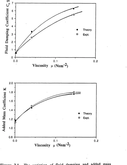
The effect o f liquid viscosity on added mass coefficient and damping o f an oscillating cylinder has been investigated both a n a ly tic a lly (b a sed on N a v ie r -S to k e s e q u a tio n s) and experimentally by Chen et al (1976). The corresponding results are shown in figure 2.1. The fluid damping coefficient is defined in section 2.3.
The data p oin ts have been obtained by extractin g the corresponding values o f added mass coefficien t and damping at a diameter ratio o f 6 where the effect o f external boundaries (see section 2.3 ) is assumed to be negligible.
A good agreem ent betw een theory and experim ent may be observed. In addition, the results indicate that the increase in v isco sity o f the liquid medium from 0.001 to 0.145 Nsm"^ results in an increase in the added mass coefficien t o f the cylinder from 1.1 to 1.8. The liquid media used in the study were water, mineral oil and silicon oil. The respective densities o f these liquids were 1.0, 0.935 and 0.956 kgm'^. Their results also showed that the effect o f the increase in viscosity within the
7
cT 6
4
Theory
Expt. â 3
2
1
0
0.0 0.1 0.2
V iscosity p (N sm ‘^)
2.0
8
uCO CO
cs
S
I
<
• Theory
a Expt.
0.8
0.0 0.1 0.2
V iscosity p (Nsm"^)
Figure 2.1 The variation o f fluid damping and added mass coefficient of a cylinder with viscosity
( Chen et al. 1976).
same range was to increase the fluid damping o f the cylinder by approximately 6%.
2.3 The E ffect of External B oundaries
The Navier-Stokes equations o f motion discussed in section 2.1 were further modified by Stokes in 1808 in order to evaluate the effect o f external boundaries on the added mass coefficient and damping o f a sphere by oscillating it in a spherical shell filled with an inviscid fluid. Full details o f the analysis are given in a publication by Lamb (1932) and hence only a brief account is given here.
For a sphere oscillating with velocity v ,in a spherical shell filled with an inviscid fluid, the total kinetic energy o f the fluid is shown to be given by
K . E , = ^ 2.27
where b is the radius o f the spherical shell, r^ is the radius o f sphere wetted by fluid and is the fluid density. If the radius ratio is expressed as ro/b = X then equation 2.27 becomes
K. Ej. = '2 2.28
Incorporating the kinetic energy o f sphere into equation 2.28, yields an expression for the total kinetic energy o f the system (sphere+fluid) given by
K. E.y - ^ 4 ^ 3 2 ^ 3 r i + 2 x ^ ^ \
■ J p p ^ r 0 + j T T p f Tq
< 1 “ X j ) 2.29
Substituting for the volum e o f sphere V=4/37rrQ^ into the equation 2.29 , we have:
K.E, =
|
Pn + 0 .5 P, 2.30comparing the equation 2.30 with the kinetic energy equation o f a body, K .E=l/2 m.v^» the virtual mass, M is given by
M = V Pp + 0. 5p^ ' l + 2X^'
V 1 - j j 2.31
and hence, the added mass coefficient K is:
K= 0. 5 'j_ + 2 x l'
2.32
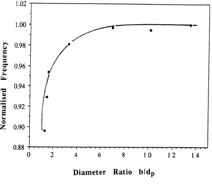
The effect o f proximity on the added mass o f a sphere oscillatin g in different diameter spherical sh ells filled with viscous fluids was modelled by Stokes in 1901 as presented in a publication by Me Connell and Young (1965). The authors also
su ccessfu lly verified the theory by conducting a series o f experiments using the apparatus shown in figure 2.2. Basically, the apparatus consists o f two parts. An upper section housing the vibrating and detection system and a lower section which holds the concentric shell together with the sphere . The source o f vibration o f the sphere is a conventional speaker connected to a horizontal beam via a rod. One end o f the rod is connected to the speaker through a spring w h ile the other end perturbs the horizontal beam , providing a connection for the sphere. The horizontal beam is held in position by two thin straps connected to the upper section o f the frame. The sphere and the concentric shell are connected to the rod during each run by a moving platform holding the arrangements. The driving frequency and frequency o f response of the rod are measured using strain gauge transducers. One transducer is attached to the speaker and another to the vibrating rod. The data in figures 2.3 and 2.4 respectively show the variation o f the added mass coefficient, K and the fluid damping coefficient, C§ with Stokes number for a diameter ratio o f 0.7400 . The Stokes number is a dimensionless parameter, analogous to the R eynolds number. It is defined as fdp2/v, where f, is the vibration frequency, dp, is the sphere diameter and v, is the kinem atic visco sity . D ifferent Stokes numbers were obtained by making up solu tion s o f various proportion o f m otor o il & k erosen e. The corresp ond ing theoretically obtained results are also presented for comparison.
From figures 2.3 and 2.4 it is evident that the added mass and the fluid damping coefficients are strong functions o f Stokes number. The slight disagreement between theory and experiment
T
1.5m
Speaker
1.85m
Speaker probe,
drive eprinoi
and pickup
beam
Support brocket
Thin strap
Anchor bolts
Spheres
Figure 2.2 Apparatus for the measurement o f added mass o f a Sphere within a concentric spherical shell filled with a fluid medium (Me Connell and Young, 1965).
c 'u
£
o>c
U
'j'.
V:
TS
"O
O)
•o T3
<
2. 1
1.9
1.7
1.5
1.3
1000000 100000
10000
100 1 0 0 0
Stokes num ber fdp^/v
F ig u r e 2 .3 The variation o f added mass coefficient with Stokes number: curve A, Stokes viscous solution; curve B, experimental results (Me Connell and Young 1965).
c/5 u
c *3
a/ O
u
&£
G
*E
B
es a ."H
'B
k 10
1
1
.01
10000
1 0 0 1000 100000 1000000 10000000
Stokes num ber fdp^/v
F ig u r e 2 .4 The variation o f damping coefficient with Stokes number: curve A, Stokes viscous solution; curve B, experimental results (Me Connell and Young 1965).
has been attributed, by the authors, to errors in determining the diameter ratio.
The fluid damping c o e ffic ie n t and added m ass w ere determined by the authors in a convoluted way by monitoring the decay o f vibration from resonance under a variety o f configurations at given diameter ratios. The fluid damping coefficient is determined from
^s~ ^ s^ ^ f ^2 2.33
where, Mf is the mass o f the displaced fluid, CO2 is the angular
resonant frequency o f the system vibrating in unbounded air and C'g is the damping coefficient because o f fluid given by
m ,
f ^ 0 in
f
^ 0
f ^ 0 Inr
X, )S 7T X , X ,
\ 1>
I
4 J
2.34the subscripts 1 and 4 refer to the system vibrating in bounded viscous solution and unbounded air resp ectively, m^, is the equivalent mass needed to be attached to the beam vibrating in unbounded air in order to produce the same resonance frequency as that obtained for the sphere vibrating in the bounded viscous solution. ( 0 and X are the resonant frequency and amplitude o f
the damped curve, n^. is the number o f cycles o f the damped curve at each condition from which the logarithmic decrement is m ea su red .
Substituting equation 2.34 into equation 2.33 yield s the e x p r essio n
“
- ( i )
CO,
2 2
\ * 2 - * 5 /
In
n Inf A . 1
2.35
from which the added mass c may be calculated.
It is worthy to note that the diameter ratio is not explicitly expressed in the above equation, however its effect is im plicitly manifested in the decay profile as measured by experiment.
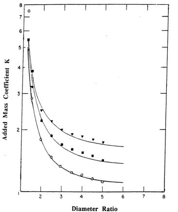
Chen et al (1 9 7 6 ) also perform ed an analytical and experim ental study o f a cylindrical rod vibrating in various viscous fluids enclosed by a rigid concentric cylindrical shell. A closed-form solution based on N avier-Stokes equation generated by authors is used to obtain the added mass and damping co efficien ts which is shown to be in good agreement with experim ental results as presented in figures 2.5 and 2.6 respectively. The fluid damping coefficien t is obtained from the frequency response curve. It is given by
Co =
Af
7I~-
2 3 6w h e r e
M . . 2.37
Diameter Ratio
Figure 2.5 The variation o f added mass coefficient with diameter ratio: o , water; ■ , mineral o i l ; ^ , silicone oil: , theory (Chen et al.,1976).
20
U
<u
o r
C u
a
2
8
7
2 3 u 5 6
Diameter Ratio
Figure 2.6 The variation o f fluid damping coefficient with diameter ratio: O , water; ■ mineral oil;
▼ ,silicone oil; theory (Chen et al.,1976).
f is the resonant frequency, and f^(^) and f^(^) are the frequencies at which the response is a factor (1/N )th o f the resonant response.
As expected, the results show that for a fixed diameter ratio, as Stokes number increases, both the added mass and the damping coefficients decrease. The results are also in good accord with Stokes theoretical prediction.
2 .4 T h e E ffe c t o f R e y n o ld s N u m b e r a n d S u r fa c e R ou gh n ess on The Added M ass
I v e r s e n and Baient (1951) in v estig a ted the effe ct o f Reynolds number on the added mass by conducting a series o f experiments in which a flat circular disk was accelerated in unidirectional motion from rest in stagnant water chosen as a low viscosity fluid. The results, expressed in the form o f added mass and drag coefficients are shown in figure 2.7. The acceleration o f the disk is represented by a modulus, aDj/vj^ where a is the acceleration o f the disk, D j is the disk diameter and v^ denotes the disk velocity. The results indicate that at the start o f motion, where fluid velocity is not appreciable (i.e. aDj/v^^ is high), the added mass and drag coefficients correspond to 0.637 and 18.0 r esp ectiv ely , w hich are the sam e as those predicted from potential analysis for creeping flow. As acceleration is increased (i.e low values o f aDj/vj^) the added mass coefficient o f the disk increases dramatically and it's drag coefficient reduces.
-0»
c 4>
’o
£
<UO u
2 *
û
20 0«
Modulus aDj/vjZ
Figure 2.7 Experimental variation o f added mass and drag coefficient of a circular disk in accelerated motion
in an stagnant water fluid medium (Inverson and Baient, 1951).
The above results were interpreted by Iversen and Baient in terms o f flow patterns generated at the vicinity o f the disk as shown in figure 2.8. At the onset o f motion, the fluid motion corresponds to that o f potential flow (Lamb 1932) as shown in figure 2 .BA . As the velocity becomes significant, (i.e. increase in inertia) a wake is formed on the downstream side o f the disk which also has to be accelerated with the body. This in turn results in an increase in the added mass. This situation is depicted in figure 2.8B.
The variation in the pressure distribution measured around a circular cylinder during its acceleration was investigated by Schw abe (1935). The results are shown in figure 2.9. The pressure distribution is expressed in terms o f (P-Po)/(0.5 p^u^) w here the denom inator is the dynam ic pressure o f the undisturbed flow, Pq is a reference pressure and P, is the local pressure o f fluid, and u, are the fluid density and velocity respectively. The results indicate that at the onset o f flow , the pressure distribution around the cylinder is sym m etrical, the same as that predicted from potential flow analysis. However, as time passes, eddies start to form downstream and the distance, dg betw een the sphere and the stagnation point behind the two vortices (the thickness of the boundary layer) increases. This is accompanied by a increase in pressure within the wake. Schwabe found that the increase in the thickness o f the boundary layer in the downstream o f the cylinder is due to variation o f pressure, a parameter which was not investigated by Iversen and Baient.
Figure 2.8 Flow patterns about a circular disk: A at the onset of motion and B with an established wake (Inverson and Baient, 1951).
3
Q.
1.0
Theory,
ste sa y
0
1
7.^J 2 4 6 ■2
3
;0
60
90
120
750
740
A /7
Displacement Angle 0
Figure 2.9 Pressure distribution measured around a cylinder during acceleration in an stagnant fluid medium(Schwabe,1935).
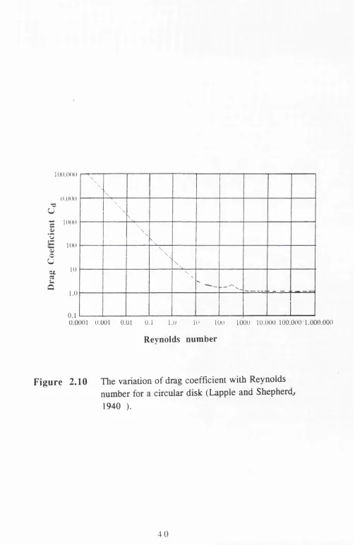
The variation o f the drag coefficient with Reynolds number for a circular flat disk in a flowing stream as reported by Lapple et. al (1940) is shown in figure 2.10 .
It is noted that at very low Reynolds numbers (ie. Re<0.1) where viscous forces are dominant, the drag coefficien t is high and the flow o f boundary layer corresponds to the creeping flow. As Reynolds number increases, the increase in inertia forces leads to the gradual replacement o f pressure drag with the skin friction drag. At Reynolds number > 2 0 0 0 the drag coefficien t becom es independent o f Reynolds number and remains at a constant value o f ca 1. It is interesting to note that the drag coefficient o f 1.1 as calculated by Iversen and Baient ( 1951) in the turbulent region is in close agreement with that obtained by M assey. The good agreement between the drag coefficien t evaluated in either case, gives a valuable confirmation to the suggestion by Iversen et al., that turbulence o f fluid boundary layer is a major contributory factor for increase in added mass coefficient o f the disk, or other shaped b od ies w h ose boundary layer is a ffec te d by the acceleration o f fluid.
Comparing the above results w ith th ose obtained by Iversen et al. it is postulated that low values o f aD^/vj^ correspond to high Reynolds number o f a body placed in the mainstream flow and the high values o f aDj/vj^ correspond to the creeping region where sym m etrical flow patterns may be o b ser v ed .
l O O . O d O
I).0 0 0
-g 1 0(K)
‘G O) c U C£
K K I
1.0
0.1
\ \
\
\ \
\ \
\ \
\ \
\ \
\ \
0.0001 0.001 0.01 0.1 1.0 10 100 1000 10.000 100.000 ; 1.000.000
Reynolds number
F ig u re 2 .1 0 The variation of drag coefficient with Reynolds number for a circular disk (Lapple and Shepherdj
1940 ).
The effect o f Stokes number on the added mass ratio (defined as the ratio o f the experimentally obtained added mass coefficient to that predicted from potential flow analysis) o f a sphere oscillating in a stagnant liquid medium investigated by Ackermann et al (1964) also confirms the above phenomenon. The results o f their investigation are shown in figure 2.11. For comparison the theoretically predicted values according to Stokes solution for a viscous fluid o f infinite extent are also included. The Stokes number is altered by changing the viscosity o f the fluid medium. From figure 2.11 it may be observed that as the viscous forces are increased the added mass coefficient increases significantly. It may therefore be deduced that the added mass coefficient is function o f both viscous and inertia forces .
Another factor which enhances turbulence is surface roughness. The influence o f surface roughness on the boundary layer turbulence at high R eynolds numbers has been under investigation by various workers.
Miller (1976) for example investigated the effect o f surface roughness on the flow past circular cylinders over the Reynolds number range o f 4.0 xlO^ to 5.0 xlO^ in a wind tunnel. The surface o f the cylinder was roughened artificially by attaching commercial sand papers around the cylinder. Figure 2.12 shows the variation o f drag coefficient with Re number for various surface roughness parameters, k / D. k is the diameter o f the surface sand particles and D is the cylinder external diameter. The data indicates that as surface roughness increases, the
■o ■o ■a <
.01
1 0 0 0 0 100000 10000
1 0 0 1 0 0 0
Stokes number fdp^/v
Figu re 2.11 Shows a relationship between added mass ratio and Stokes number for various diameter ratios: O ,0.259; □ , 0.518: ■ , 0.60; L , 0.691;
• .0.777; S ,0.864: k .theory (Ackermann and Arbhabhirama, 1964).
u
Oi u
r
C U
Cl
Î3 L.
C -7 6 ! 5 0 0
02
Reynolds number
Figure 2.12 The effect o f surface roughness on the drag coefficient of a cylinder for steady flow ( M iller 1976).
transition from subcritical to transcritical flow occurs at lower Reynolds numbers
2.5 T h e E ffe c t o f A d ded M ass on T h e S ta b ility o f F lu id ise d B eds
When the flow rate o f the fluidising medium in a fluidised bed is increased, one o f two things can happen. Either the bed continues to expand thus, in creasin g the p a rticle-p a rticle distances or the expansion occurs up to a certain limit which is then follow ed by formation o f bubbles. The transition from the uniform particulate behaviour to the aggregate bubbling stage represented by Gmy(i.e. min. bubbling voidage) is said to mark the onset o f the instability o f fluidised beds (Foscolo et al, 1984). This phenomenon is o f particular industrial importance since the formation o f bubbles results in large deviations from the more desirable plug flow behaviour. A lso, the by-passing o f solids by bubbles produces an inefficient contacting system which is o f particular concern in cases where high conversion o f reactants is required (Kunni et al., 1969).
In recent years, a number o f m odels have been proposed which predict, with varying degrees o f su ccess, the transition from particulate to aggregate fluidisation. The follow ing is a historical review o f such models which characterise the behaviour o f flu id ised beds by con sid erin g flu id -p a rticle interactions. More recent approaches are also review ed which highlight the im provem ents in the predictions obtained by
incorporating the added mass contribution in the fluid-particle interaction forces.
2 .5 .1 T h e o r e t i c a l C o n s i d e r a t i o n o f F l u i d i s e d B e d B eh aviou r; P a r tic u la te to A g g reg a te T r a n sitio n
The study o f particulate and aggregate fluidisation , based on the fluid and particle properties, was first tackled by Jackson (1963) and later by Pigford et al. (1965) and Murray (1965). A common conclusion emerging from these studies indicated that the flu idisation process is essen tially an unstable p rocess, regardless o f fluid - particle system involved . The difference between typical gas and liquid fluidised beds is simply due to the greater disturbance growth rates o f void age perturbations with time for gas fluidisation, which results in eventual complete formation of voids or bubbles.
The results o f these models were in contradiction with long e sta b lish e d exp erim en tal o b serv a tio n o f p a rticu la te and aggregate fluidisation, which indicates that the gas fluidised beds expand in an unam biguously stable, particulate manner with increasing gas velocity up to a critical value o f the void fraction, (the minimum bubbling voidage , Gmb)» where there is an abrupt
change to a vigorously bubbling, aggregate state. Liquid fluidised beds on the other hand, in general adopt hom ogeneous or particulate characteristics, which is to say that they display essentially uniform suspensions o f the fluidised particles that simply become progressively more dilute as the fluid velocity is in crea sed .
The failure o f such models to predict the criteria for the transition from particulate to aggregate fluidisation, initiated the work by Foscolo, et. al (1984), which is formulated on the basis o f the fluid-particle interaction forces .
The feature o f the particle bed model formulation that most d istin gu ish es it from alternative treatm ents o f flu id isa tio n dynamics, lies in the development o f an expression for predicting the dynamic wave velocity solely in terms o f the basic system properties. It is this term that enables predictions to be made concerning the stability o f the uniform fluidised state.
M athem atically, the dynamic w ave velocity for a sin gle phase (i.e. particle phase) is shown to be given by ( Foscolo et. a l , 1 984)
Ue,=
2.38
where, pp is the particle density, pf, is the fluid density, e, is the voidage, dp is the particle diameter with g representing the gravitational force.
According to W allis (1969), the transition from particulate to aggregate behaviour occurs when the dynamic wave velocity , Ug is equal or smaller than the voidage propagation velocity, u^. Occurrence o f voidage propagation waves in fluidisation is found to be due to a sudden change in fluid velocity from one constant
value to another. This causes the bed surface to fall at a constant rate which is equal to the imposed change in superficial velocity. This process gives rise to a one-dim ensional shock wave that propagates upwards, also at a constant rate. On the other hand , direct measurements o f dynamic waves in fluidised beds are not generally possible as they either grow into shocks or decay away according to the particular system properties and conditions o f operation. W allis (1962) how ever has described a method for measuring their velocity at incipient fluidisation conditions, and results have been obtained for cases o f water fluidisation .
The method involves fluidising particles in a bed fitted with a mesh screen at the top. By increasing the fluid velo city , particles become packed against the screen; by then reducing the flow to a value one and two tim es the minimum fluidisation velocity. Particles at the bottom interface o f the packed section rain down giving rise to an easily measurable dynamic shock wave. By performing this experim ent at a number o f fluid v elo cities, the dynamic w ave velocity at minimum fluidisation can be obtained by extrapolation .
The velocity o f voidage propagation wave ue is given by (Slis et al. 1959)
Ue = n v ,(l - e)e" '' 2 . 3 9
where, n is the Richardson-Zaki constant and v^ is the settling velocity o f unhindered particle.
The above equation follow s from derivation o f the equation given by (Slis et al. 1959)
where, dv/de is the variation o f particle velocity with voidage.
Equation 2.40 represents the voidage propagation velocity in fluidisation for an infinitesimal perturbation from equilibrium conditions .
The criterion for the onset o f instability is therefore given b y
Ue = Ue 2.41
Substituting the corresponding expressions for u^ ( Foscolo et al., 1984) and u^ into equation 2.41, we have
9dp(pp - P f )
2 - 0. 5 6n( 1 - e. ’ = 0, s t a b i l i t y l i mi t
V. Pp
+ v e , s t a b l e ( p a r t i c u l a t e ) - v e , u n s t a b l e ( a g g r e g a t e )
2.42
where, Gy, is the voidage at which a transition from particulate to aggregate fluidisation occurs. For cases o f practical interest, Gy = Gmb.
Figure 2.13 is a comparison o f the voidages, £mb at which bubbles start to occur as predicted from equation 2.42 against the corresponding exp erim en tally m easured valu es reported by various authors for gas fluidised beds operating at various ambient pressures. The good agreement between the theoretical and the experim entally obtained results is an indication o f applicability o f the model for gas fluidisation operating under various pressures.
Unfortunately, precise data on the particulate to aggregate transition behaviour is not available for liquid beds. However, the experim ental results produced by Harrison et a l.(1 9 6 1 ), showing how a progressive variation o f either liquid or particle properties can lead to the bubbling behaviour o f liquid fluidised beds are compared with those predicted from equation 2.42. The overall results are summarised in tables 2.1 and 2.2 . The agreement betw een the two , offers further evid en ce for the general applicability o f the proposed model by F oscolo et al. (1 9 8 4 ).
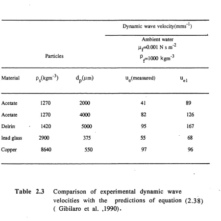
In a later publication, Gibilaro et al. (1990) made a direct com parison betw een the dynamic w ave v elo city as predicted from equation 2.38 and the corresponding exp erim en tally measured values for various density particles in a liquid fluidised bed. The results are summarized in table 2.3. As it may be observed, the agreement is generally good except for the low density particles where the velocities predicted from the model are higher than those given experimentally.
|.0
0.0
s
S
u x>g- 0.6
w
-O
E
1 0
0 .4 0.6 0.8 1.0
o
6inb Calculated
Minim um bubbling condition for gas flu idised beds; comparison o f experimentally determined values o f
with predictions o f the stability criterion; eq u ation 2.4 2, o Musters and Rietema( 1977), + Rowe et al.(1982), x
Re Experimental observations Prediction o f proposed criterion, equation 2.42
2 . 1 Particulate fluidisation No transition to aggregate
fluidisation
6.3 Particulate fluidisation No transition to aggregate fluidisation
54.6 Aggregate behaviour observed
Aggregate fluidisation for 0 .5 6 < e <0.93
316.5 Aggregate behaviour observed
Aggregate fluidisation for £< 0.97
Table 2.1 The transition from particulate to aggregate fluidisation in liquid beds. Comparison o f the results o f Harrison et al. (1961) with the prediction o f equation( 2.42 ) for various
liquids. System: lead shot; glycerol-water mixtures; pg=11320 kgm"^
( Foscolo et al. , 1984)
dp=0.77mm.
Material
Particle Density
(k g m
Re, Experimental
observations
Prediction of equation 2.42
Resin 1500 8.7 Particulate
fluidisation
No transition to aggregate
fluidisation
Glass 2900 32.5 Particulate
fluidisation
No transition to aggregate
fluidisation
Steel 7430 72.1 Aggregate
behaviour
Aggregate fluidisation for0.5<e<0.95
Lead 11320 100 Aggregate
behaviour
Aggregate fluidisation for 0.42<e<0.97
T ab le 2.2 The transition from particulate to aggregate fluidisation in liquid beds. Comparison o f the results o f Harrison et al. (1961) with the
prediction o f equation ( 2.42 ) for various particles. System: solid spheres, paraffin;
pf=780 kgm"^ , jLi =0.002 Nsm’^. ( Foscolo et al. , 1984)
Particles
Dynamic wave velocity(mms’^) Ambient water
Mf=0.001 N s PplOOO kgm‘^
Material Pg(kgm'3) dp (pm ) Ug(measured) "el
Acetate 1270 2000 41 89
Acetate 1270 4000 82 126
Deirin 1420 5000 95 167
lead glass 2900 375 55 68
Copper 8640 550 97 96
Table 2.3 Comparison o f experimental dynamic wave
velocities with the predictions o f equation (2 .3 8 ) ( Gibilaro et al. ,1990).
F oscolo et al (1989 ) attributed to the above discrepancy due to the following reasons
a) The fluid pressure acting on the particle in the model was approxim ated by the expression for it's mean value in a homogeneous unperturbed bed . This is given by
where, is the variation o f fluid pressure on a particle, 6 is
the bed voidage, and Pp are the fluid and particle densities.
As a consequence o f this approximation, the particle phase in fluidisation is taken as a non-flow ing fluid, leading to the underestimation o f dynamic wave velocity predicted by equation 2 .3 8 .
b) Added mass is another factor to be taken into considerations when there is a relative acceleration between the particle and fluid phase. This effect is expected to be n egligib le for gas fluidisation, where the particle density is so much greater than that o f the fluid . For liquid fluidisation o f relatively low density material, however, the effect could be significant. This w ill in turn be manifested in an error in the prediction o f the dynamic wave velocity and hence the onset o f instability.
The problem o f fluid pressure field approximation was overcome by W allis(1969) who dealt with the general two-phase problem by using both phase momentum equations to eliminate the common pressure gradient term and hence, arrived at a more complete formulation for dynamic wave velocity given by
(1 + R) 2.44
with
D _ Cp) Pf
(Go Pp) 2.45
where, Ufo is steady-state fluid interstitial velocity, Uei is the dynamic wave velocity derived from the single phase model and Gg, Steady-State bed voidage.
Table 2.4 shows the variation o f dynamic wave velocity as pred icted from equation 2 .4 4 again st the ex p erim en ta lly m easu red v a lu e s for d iffe r e n t d e n sity p a r tic le s . T h e corresponding data obtained using the simple model as described by equation 2.38 are also included for comparison. For the case o f a fluidised bed where the particle density is generally much greater than that o f fluid , the two phase model approaches the single phase approximation, for most cases o f practical interest, which includes all gas fluidised systems and liquid fluidisation o f moderate density particles. W hereas, for lighter particles , the
Dynamic wave velocity (mms'^) Ambient water:
viscosity= 0 . 0 0 1 Nsm"^
D ensity= lOOOkgm"^
Material Pp(kgm"3) dp(jum) u^(measured) ^el ^e2
Acetate 1270 2000 41 89 64
Acetate 1270 4000 82 126 92
Deirin 1420 5000 95 167 127
lead glass 2900 375 55 68 56
Copper 8640 550 97 96 96
Table 2.4 Comparison between experim ental and theoretical values of dynamic wave velocity . u^j: predicted from equation 2.38 and u^ 2 predicted from
equation 2.44.
discrepancy observed in the table 2.4 can be substantially red u ced .
Although the solution to the pressure gradient improves the dynamic velocity values o f low density particles greatly, h ow ever, the d iscrep an cy b etw een the exp erim en tal and th eoretical value o f dynam ic w ave v e lo c ity in d icates the importance o f the added mass which was ignored in the previous two phase analysis.
Gibilaro e al. (1990) improved the theoretical consideration further, by employing the fluid and particle forces derived from the previous analysis (1984, 1987) into à combined momentum equation o f two incompressible phases in a one-dimensional flow derived by Wallis (1989).
Wallis's equation was derived, from the basic assumption o f Guerst (1985) for the kinetic energy density, K .E.j, for two-phase flow . This is given by
K + - ^ P p ( l - e ) v^ + ^ P j C , ( u - v ) 2 46
all the sym bols in the above equation have been described previously. The first and the second terms o f the above equation represent the k in etic energy due to flu id and p article respectively and the last term represents the kinetic energy due to flow field brought about by the relative motion between the
fluid and particle phase. The constant Ci in the last term is defined as the inertial coupling coefficient, and for the case o f a "Maxwellian suspension " adopts the form given by:
C |- —5 ( 1 - e)
2.47
where, C% is the inertial coupling coefficien t and e is the bed v oid age.
Using the appropriate expression for C\, for the case o f a solitary particle travelling through a stagnant in v iscid fluid, delivers the expected result for the total kinetic energy, K.E.j;
K.E^ = -iM v '
2.48
where, M is the sum of the particle mass and one half the mass o f the fluid that the particle displaces. This provided the ground for the work by W allis (1989), who incorporated the added mass effect into the formulation o f combined momentum equations for two incom pressible phases;
■ a v
a v ■
■ a u
a u i
+ v a z j - p , | . a t " " Oz _
+ f , - f p = 02 . 4 9
leading to a similar equation given by