Model Execution: An Approach based on
extending Domain-Specific Modeling with Action
Reports
Verislav Djukić1, Ivan Luković2, Aleksandar Popović3 , and Vladimir Ivančević2
1 Djukić – Software Solutions, Gärtnerstrasse 17, 90408 Nürnberg, Germany
2 University of Novi Sad, Faculty of Technical Sciences, Trg Dositeja Obradovića 6, 21000 Novi Sad, Serbia
{ivan,dragoman}@uns.ac.rs
3 University of Montenegro, Faculty of Natural Sciences and Mathematics, Džordža Vašingtona bb, 81000 Podgorica, Montenegro
Abstract. In this paper, we present an approach to development and application of domain-specific modeling (DSM) tools in the model-based management of business processes. The level of Model-to-Text (M2T) transformations in the standard architecture for domain-specific modeling solutions is extended with action reports, which allow synchronization between models, generated code, and target interpreters. The basic idea behind the approach is to use M2T transformation languages to construct submodels, client application components, and operations on target interpreters. In this manner, M2T transformations may be employed to support not only generation of target platform code from domain-specific graphical language (DSGL) models but also straightforward use of models and appropriate DSM tools as client applications. The applicability of action reports is demonstrated by examples from document engineering, and measurement and control systems.
Keywords: domain-specific modeling, model-driven development, model transformations, modeling tools, document engineering
1.
Introduction
proclaimed goals related to development productivity and software quality [19], [21]. Some authors consider the unfitness of UML for domain specific problems to be the main reason for this failure. Expecting that an average software engineer uses or thinks in domain independent abstractions might have been unrealistic. Several approaches, including Domain Specific Modeling (DSM) and MDSD, still focus on software models, which are sufficiently formal but also understandable to both machines and humans. One of the important goals in the aforementioned approaches is that models should not only be part of the specification but also of the implementation of the corresponding systems.
Software industry experts are more pragmatic in regard to these issues and not determined to use general purpose modeling languages, such as UML, at all costs. They are more focused on developing modeling tools that satisfy requirements for highly specialized production and control systems. Although the quality and usability of these tools are not being questioned, the manufacturers are constantly faced with high costs of development and customization, even for very similar domains. Taking all into consideration, we expect that the software industry will base its highly specialized tools on the DSM architecture to a much greater extent. The following two improvements could be particularly important: (i) better support for the construction of modeling languages and their syntax, including abstract, concrete graphical, and concrete textual syntax; and (ii) better synchronization between meta-models, models, generated code, and target interpreters or “execution machines”. Our research is oriented toward the latter improvement, i.e., better synchronization between meta-models, models, generated code, and target interpreters. The aforementioned synchronization is closely linked to model debugging and execution.
Action Reports
engineering, there is support for a one-way synchronization. One of the future research tasks includes implementing in IIS*Case the automatic two-way synchronization between the model and the system executing the applications. As opposed to the existing abovementioned approaches to the execution of models created using a DSM tool, our approach supports incremental interpretation of specifications. Each user operation on a model in the DSM tool is directly interpreted in real time, which may be utilized to verify the correctness of the specification. Simulation tools have supported this approach for quite some time, but they set restrictions on the semantics of simulation languages, i.e., meta-modeling is considerably limited. The execution of models whose semantics is not known in advance represents a significantly more complex problem with respect to both the theoretical and practical issues. The most difficult problems are the definition and automatic generation of a target interpreter that supports incremental verification of specifications. Moreover, the goal of our approach, to which we actively direct our efforts, is to support the two-way synchronization by allowing the direct execution of changes on a model. This may be achieved by using operations on the application that represents the result of the incremental specification. There should be support also for the direct extension of a meta-model in real time according to the operations executed on the previously created models.
Our initial application of MDSD, DSM, and model transformation principles is related to complex problems in document engineering, previously presented in [7], [11], [14], [22], [24], [26]. Positive experience with the construction and application of domain specific languages (DSLs), together with problems related to the development of client applications for measurement and control systems, indicated that the Model-to-Text (M2T) transformations in DSM may be significantly improved and utilized in model debugging and execution. By employing extended M2T transformations, namely "action reports”, we intend to make possible the use of modeling tools as client applications. Notwithstanding the fact that current techniques for code generation from models have great capabilities, we demonstrate herein the practical value brought by: the introduction of the submodel concept and appropriate operations; the introduction of the transaction concept in the context of (sub)models; and the use of action reports (generators) as synchronization units during the testing of meta-models, models, client applications, and target interpreters. The practical value of introducing submodels, transactions, and action reports, is that M2T transformations, in addition to being employed for the generation of code in a target language, may also be used for expressing semantics of user actions on a PIM, i.e., on the graphical interface of a DSM tool.
includes interaction between all of the components in the DSM architecture, incremental specification, and visual representation of all changes within a real system being modeled. We took a pragmatic approach to the issue of model execution, with the goal of having solutions that may be sufficiently understood by a wide range of users and quickly applied in various business domains. The emphasis is placed neither on the definition of syntax of user semantic actions, nor on meta-modeling, but on the definition of action semantics, i.e., on the interpretation of user actions in a DSM tool during their execution and not solely afterwards, during code generation.
Besides the Introduction and Conclusion, the paper contains eight sections. In Section 2, we describe the state of the art and what is expected from DSM for model execution. The description of the concept of action reports and how they differ from code generators may be found in Section 3. In Section 4, we describe Model-to-Application (M2A), Application-to-Model (A2M), and Model-to-Document (M2D) transformations with respect to application generation. In Section 5, we describe usage of submodels and transactions in the testing of a DSL, model, and target framework or interpreter. This is illustrated with examples of using DSM tools for modeling documents, document templates, and modeling systems by documents. In Section 6, we describe how arbitrary user components may be integrated into DSM tools with the goal of visually representing abstract language concepts. In Section 7, we give examples of the synchronization between a client application and modeling tool. Section 8 describes usage of action reports for the purpose of implementing operations on DSM models, the target interpreter, and user applications. Chapter 9 contains a survey of related work, and overview of the current state of technology in the area of model execution.
2.
State of the Art and MeMID Activities
Action Reports
observations are fairly general since there are significant differences even between the tools of the same group.
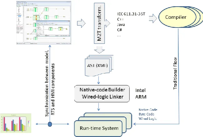
Further evaluation of the state of the art in the area of model execution is done with respect to the aspects of traditional and advanced code generation and execution (Fig. 1). A modeling language is constructed using a dedicated editor, while models are created using the newly constructed language. In the DSM architecture, these steps correspond to meta-modeling and modeling activities. PIMs are transformed into source code in a general purpose programming language. Transformations are done using patterns or navigation languages [15], [30]. The generated source code in some language (e.g., IEC 611.31, C++, Java, and C#) is translated into binary code using a compiler so that it could be executed on the target platform. This DSM use case is marked as Traditional Flow in Fig. 1. In some cases, target platforms are operating systems themselves, but they may often be Run-Time Systems (RTSs) or Execution Machines, which feature a set of functions more suited for the concrete purpose when compared to operating systems. In our opinion, traditional use of DSM tools significantly improves productivity in the system development, but also has serious drawbacks.
The basic drawbacks of the traditional approach include: (i) weak synchronization between the generated code, model, and meta-model, which hinders incremental execution of models; and (ii) growth of specifications. As the specification is growing, the model should be executed accordingly, first, as empty, and later as more complex, while for each action on the model there should be a corresponding interpretation in the target RTS.
In the traditional approach, which is based on transformations into a general purpose language, the semantics expressed by a PIM may be significantly limited by a transformation to a target general purpose language (GPL). The approach that we propose, which is illustrated herein in Fig. 1 and with several examples tested in practice, includes:
direct translation of PIM models to binary code tailored to the characteristics of the target RTS and hardware;
dynamic linking of specifications being executed using increments, which are the result of changes in the model;
use of action report interpreter within DSM tools, Human-machine interface (HMI) components, and the RTS for the purpose of their synchronization; application of arbitrary user components for the visualization of abstract
DSL concepts; and
run-time visualization of the interpretation of specifications within the DSM tool.
As indicated in Fig. 1, at the level of M2T transformations, an extended abstract syntax tree (AST) is generated. It is an Extensible Markup Language (XML) structure, from which it is possible to generate code in binary, assembly, or a general purpose programming language. Depending on the characteristics of the RTS and target hardware, various protocols for dynamic linking of binary code to the RTS are employed. These protocols specify how to exchange data on variables, arrays, user structures, external functions, and values of object instances. If the modeling language is sufficiently rich, there is no need for a host language, and, consequently, for a GPL compiler. We consider this approach especially suitable for target RTSs that support: incremental updating, dynamic linking of binary code, and execution of instructions used to communicate with wired logic controllers. The target system may also be a virtual machine, which executes byte code. We use the term byte code to denote a set of platform independent assembly instructions that are primarily intended to be interpreted by virtual machines. Due to their slow interpretation times, virtual machines are generally not suitable for systems that should have a prompt and time-determined response.
The tracking of model changes presents an important research topic of practical relevance to the Model-Driven Development (MDD) community. In [29], the authors introduce new features of the MetaEdit+ Workbench [30] and present various capabilities for visualizing language concepts of a DSL, including dynamic modification of appearance properties. The MetaEdit+ Workbench is a tool that provides support for various development phases including meta-modeling, modeling, code generation, and simulation of the modeled system. In our approach, we borrow two well-established ideas that are implemented in modern database management systems: transactions and views.
Action Reports
substantially more complex. The standard debugging scenario is conceptually restricted by operating systems, target frameworks, and libraries. Therefore, any pragmatic approach featuring even minor improvements related to MeMID activities is going to represent a significant contribution to the testing of domain-specific models.
3.
Action Report as an Extended M2T Transformation
An action report is a special M2T transformation formally defined using a language for specifying code generators that, in addition to the description of the model-to-text transformation, contains commands and rules for command invocations during model execution. DSM involves use of reports, also known as generators, to specify how to utilize information from abstract models and to generate code in accordance with a particular concrete syntax [3], [14], [20], [30]. A report is a program whose interpretation yields a textual representation of the semantics expressed in a model. Since transformation languages support model filtering by selection of objects and relations according to a criterion, they should be used to explicitly define a submodel or model view. The need to introduce submodels arises from the fact that, in practice, testing is most of the time focused on a single part of the system and not on the system as a whole.
The purpose of extending report languages and their interpreters is to improve synchronization between a modeling tool, target interpreter and client applications that are not generated by the modeling tool. Therefore, an action report is a report containing synchronization commands. Accordingly, an action report interpreter is an extended code generator that, in addition to reading, may change the state of a model, meta-model, client application and target interpreter. Put in simple terms, an action report features set and get operations for property values. In such role of action reports, it is assumed that every participant in the synchronization has an instance of the action report interpreter.
Relevant characteristics of action reports are divided into three groups: (i) those that are related to modeling tools; (ii) those that are related to target interpreters; and (iii) those that are related to user components for visualizing and documenting actions.
The first group includes the following characteristics: (i) action reports are defined in the context of a submodel; (ii) action reports allow frequent model view changes, i.e., frequent submodel redefinitions; (iii) action reports are executed inside an optimized transaction whose beginning and end are tied to valid model states; and (iv) action reports may execute operations (and be referenced) in the context of both concepts forming a meta-model (modeling language) and objects not part of the meta-model, i.e., any user control.
increment between two model states; and (ii) when employing models to manage business processes, action reports may be used to synchronize business activities prior to a switch to a new management model, as well as to incrementally generate documentation and applications that precede the change of the business model.
The third group includes the following characteristics: (i) all the communication between modeling tools and external applications is in the form of textual commands specified in the syntax of a generator language; (ii) action reports are closely related to target interpreter environments, which may vary greatly; (iii) action reports may be called both synchronously and asynchronously, while calling rules define order, frequency, and/or logical conditions related to the call; and (iv) if the target interpreter does not support incremental update during interpretation time, the problem is reduced to the recompilation of the generated code and the use of appropriate debugging tools, which are often part of IDEs.
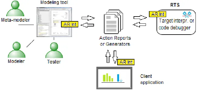
The role of action reports is illustrated in Fig. 2. They are primarily an interface between the modeling tool, user applications, and target interpreter or debugging environment for the generated code. The interpretation of action reports is performed by special components that are instances of action report interpreters, which are labeled AR Int within the little yellow rectangles featured in Fig. 2. The objective is to allow various user groups like meta-modelers, modelers, testers, etc., to use an existing DSM tool as a means of testing the generated code, target interpreter, model and DSL. Action reports are not intended to be used for the description of dynamic characteristics of a system. These characteristics may be completely formally specified through UML state diagrams or equivalent DSLs. Action reports are employed to allow direct use of the existing DSM graphical interface in debugging or testing of the generated code.
Action Reports
When the modeling language is not sufficiently semantically rich, generators may be temporarily used to describe semantics, i.e., surpass problems caused by the lack of DSL concepts. This scenario is typical particularly for the DSL construction phase.
We close the action reports introductory section with a remark that the importance of action reports as defined herein may significantly differ depending on the actual context. In some business domains, the feedback that action reports may provide to modeling tools has no relevance. However, when DSLs are used in specification of measurement and control processes, action reports are essential and their use brings numerous advantages [29]. A modeling tool may be used as an HMI by exploiting the feedback from the target interpreter. There may also be different visual representations of a single language concept.
4.
M2A , A2M, and М2D Transformations
For the purpose of investigating and verifying practical usability of Model-to-Application, Application-to-Model, and Model-to-Document transformations, we implemented the DVRepLang language for specifying these transformations and a corresponding interpreter [8], [14]. They are part of DVDocIDE [10], a DSM tool for document modeling. М2А/А2М transformations are basically М2Т/Text-to-Model (Т2М) transformations whose purpose has been described in various papers [30], [34]. M2T transformations have been applied in numerous tools for code generation from models [2], [14], [15], [20]. The motivation for introducing M2A/A2M transformations in our research is differentiating in code generation between: (i) procedures that generate the code for the communication between modeling tools and a target interpreter and (ii) procedures that generate the code to be interpreted or executed on the target interpreter. The procedures that generate the code responsible for the communication are tailored to the characteristics of communication components, i.e., communication frameworks. On the other hand, the procedures that generate the code being interpreted are tailored to the characteristics of the framework and target system. The semantics expressed by the model is interpreted by this target system independently from the manner in which the communication is performed. For example, if both frameworks are inadequate, the communication procedures may generate TCP/IP commands, while the procedures responsible for expressing the semantics of the model may generate code in C++. In this context, the target interpreter is important as a component that verifies model and gives feedback for the potential refinement of both the model and DSL. The reason for introducing the notion of a M2D transformation is a need to extend M2T transformations with procedures for the generation of documentation about the MeMID activities.
target text is a code in a GPL, DSL, or any textual format interpretable by a modeling tool or a target interpreter;
target text contains embedded semantic actions like property get and set operations;
operations may be performed on models inside a repository or locally on visual representations of DSL concepts in the graphical interface of a modeling tool;
these transformations may include operations on external elements of the presentation that are not part of the modeling tool (see Fig. 3);
these transformations do not directly modify the meta-model, but are used for the semi-automatic inclusion of user controls that graphically represent language concepts; and
when there is a discrepancy between the concepts directly supported by the interpreter and those of the DSL, these transformations provide an interface for the communication between the relatively incompatible units. The most important characteristics of М2D transformations include:
target text is a specification of document instances in a DSL;
such specification contains identifiers of layout styles that are used for the document rendering;
target interpreter, which features an instance of the action report interpreter, utilizes action report definitions as a basis for the identification of rules and conditions for initiating document rendering; and
M2D transformations include rendering of well-designed documents in the PDF or HTML format in the form of external services.
By introducing these transformations, we satisfy some of the user requirements related to the more agile testing and documenting of DSLs, models, and target interpreters. The ideal environment for the application of these transformations within the MeMID activities is the one that supposes the existence of the “universal interpreter” and does not require interrupting the interpretation during the synchronization of model changes. These “hot” switches to a new version of the model are known as incremental updates. Universal interpreters that are independent of the application domain do not exist. Any generalization of the target interpreter necessarily leads to a greater separation of the language used to describe the problem from the language interpretable by the interpreter. In practice, there is a compromise to solve the widest possible class of problems by upgrading the interpreter so that it could internally translate DSL constructs that are at a high level of abstraction to an optimized set of elementary operations.
Action Reports
interpretation [29]. The debugging of DSM models cannot be equated with the debugging inside GPL IDEs. With the GPL-to-assembly transformations, there is a finite, predetermined set of source and target language concepts. On the other hand, in DSM neither the source nor the target language needs to be known in advance. The source language is constructed to meet the domain-specific needs and the target code may substantially depend on the existing libraries and frameworks. One of the approaches to the formation of a stronger logical relationship between debugging environments and modeling tools includes the use of patterns. In this manner, it is generally possible to relate the model to the target code. One disadvantage of the use of patterns is that they need to be created for each combination of a DSL and target platform. The critical issue is how efficient the debugging of the resulting code is when done through a GPL IDE that is logically separated from the meta-modeling tool. This problem is extensively debated and the proving of the language validity is a topic of numerous papers and books [21], [27].
Further discussion of MeMID activities is based upon an assumption that the debugging rules or steps should be defined inside the М2А, А2М and M2D transformations in order to provide the feedback from the target interpreter toward the model.
5.
Using Submodels, Transactions, and Action Reports in
MeMID activities
Modeling tools usually support the concept of model decomposition, which implies that an object, relation, or role may be linked to a submodel. This allows for a model to be described and expressed at different levels of granularity and sometimes even at different levels of abstraction. During testing, it is necessary to focus on just a subset of elements within the model. In DSM tools, this subset should be defined using a submodel, as a complex object with its own structure, operations, and constraints. Although default operations (insert, delete, connect, and disconnect) and constraints express fundamental dynamics of the system described by that model, they are not sufficient to express the rules for the translation of the model from one consistent state to another. For this reason, modeling tools should include support for the transaction concept. Transaction is defined as an operation that validates a sequence of actions on a model and updates the repository. Similar to the database transaction, it includes a validation of actions in the context of MeMID activities. Therefore, we expect that modeling tools explicitly support defining submodels, similarly to how it is supported in DVDocIDE [10].
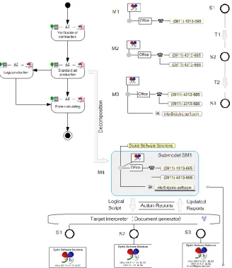
consists of several activities in the modeling of small advertisements. To model advertisements, we use a DSL named DVAdLang, [5], [11]. The subgraph of the object A2, marked with M4, is an advertisement model that features a logo, several phone numbers, and an email address. In the upper right section of the figure, there are three models (M1-M3) in three consistent states (S1-S3), all of them representing the same advertisement. These advertisements states, which are explicitly expressed by their models M1-M3, are evaluated in the context of the submodel SM1, which does not contain the advertisement title (the yellow rounded rectangle).
With respect to model execution, there are two levels of verification: (i) model verification during design time, done by the modeling tool and in accordance with the meta-model; and (ii) on-demand verification of the code generated from the model, whose form of invocation is explicitly expressed by transactions, i.e., action reports in a M2A transformation (in Fig. 3 marked by T1 and T2). Successfully completed transactions change the advertisement states while giving a visual representation for each of these states, i.e., they document the changes in the advertisement states using well-designed PDF documents (see the lower section of Fig. 3). Partial verification of a model, herein illustrated by the example of the submodel
SM1, which is represented by a shaded rectangle with rounded edges, is not directly supported in standard DSM tools. This fact hinders a wider use of DSM tools in certain domains, such as document engineering and incremental specification of measurement and control processes. In the presented example, we implemented this functionality using the incremental document generator DVDocGen [6] as the target interpreter. In this manner, we obtained advertisement images, which are shown in the lower section of Fig. 3. DVDocGen can detect, interpret, and update action reports. The DSM modeling tool needs to interpret only a property value set operation in order to visualize the model execution flow. As opposed to DVDocIDE [10], which is focused on the formal specification of documents, general purpose DSM tools mostly do not support such operations.
Examples 1 and 2 further refer to the contents of Fig. 3 and include: (i) specification of the action report AR1, which sets the text property
Font.Underline in the objects in the modeling tool; and (ii) a generic form of a DSL script, which is an interpretable textual representation of a portion or whole semantics expressed by a model.
Action Reports
Fig. 3. Submodels, transactions, and testing of models and the target interpreter
Listing 1. Action report example
Report 'AR1'
CALL_TYPE = event; /*interval,cyclic,event*/ foreach >ContentUnit {
do .() {'<'type '>'
if type = 'LOGO' then
ID ',' :Alignment; ',' :Height; else :Value; endif
newline
{
'<' type '>' :Value; newline ACTION_BEGIN
'<STATE>'objID
:Font.Underline=true; ACTION_END
} }
The existing syntax of DVRepLang, which is used for М2Т transformations, is extended with: (i) CALLTYPE command for the declaration of conditions or intervals for the exchange of action reports with the target interpreter, and (ii)
ACTIONBEGIN and ACTIONEND primitives, which mark a report code
section related to synchronization. In Listing 1, the new language commands are marked in bold.
Example 2. During the interpretation of the AR1 report from Example 1, a DSM tool generates target text. In this particular case, it is a DSL script in the DVAdLang syntax, which is featured in Listing 2. The definition of action reports is inserted into the <ARMETA> tag. This definition is required by the target interpreter during the whole synchronization process done with the modeling tool and client applications.
Listing 2. Embedded definition of an action report in the DSL script
<AR_META>="REPORT AR1..." <CU>Initial DSL script <STATE>S1
<CU>Increment for S2 (Transaction T1) <STATE>S2
<CU>Increment for S3 (Transaction T2) <STATE>S3
The <STATE>objID commands in a DSL script in the target language explicitly denote states, and define transitions and semantic action during model execution. During the interpretation of each <STATE> command, a client application or document generator finds an action definition within the <AR_META> tag and executes that action while informing the modeling tool about the interpretation state. In this example, the property-setting operation
Font.Underline=true (marked by ACTION_BEGIN and ACTION_END) is
called.
Action Reports
6.
User Application and Modeling Tool
In a typical DSM scenario, HMI components of a user application are generated or parameterized from models. User applications are not utilized in modeling but are products of modeling that are obtained in the automatic generation of source code. In environments where DSM is being applied, users often have their own framework and HMI components whose layout and functionality are too complex to be specified using editors for meta-modeling. Therefore, it is useful to allow simple integration and use of external HMI components in DSM tools. This integration does not only include exchange of values according to the scenario described in the previous section, but also implies use of external HMI components for visual representation of abstract DSL concepts. In the following discussion, we restrict ourselves to the pragmatic approach that utilizes action reports and common properties of visualization elements in the DSM tool and HMI components.
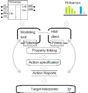
In Fig. 4, we illustrate an approach to the integration of user HMI components into DSM tools. In the upper left corner of Fig. 4, there is a function block object in a default visual representation created using a DSM tool. In the upper right corner of the same figure, there is a user HMI component that in the form similar to a bar chart shows input and output values of variables associated with the function block. The output variable
out2 is of the bool type, so it is represented in the HMI component as an empty circle when its value is false, or as a filled circle when its value is true. Both the DSM tool and the HMI component support reading and changing the property values in several ways, e.g., mouse operations and using a text editor. The P(dsm) label denotes properties defined using the DSM tool, while the P(hmi) label denotes properties belonging to the HMI component. The integration procedure consists of three steps: (i) property linking (also shown in Fig. 4), in which the semantically equivalent properties are found between the two visual representations, irrespectively of the actual form of visualization; (ii) defining user actions on the elements of the graphical representation when certain semantic actions should be executed (labeled
Action specification in Fig. 4); and (iii) defining the semantics of actions using a language for action reports.
The target interpreter, which is shown in the lower section of Fig. 4, executes the current specification, i.e., interprets the model and action reports. In the context of the target interpreter, it is not important whether the action reports were created by a DSM tool or user application. The role of the target interpreter is to fetch the values of some properties from the current state of the interpretation, update the action report, and send it back. The communication may also go in the opposite direction. Based on the state of the real system, the target interpreter detects the conditions when the semantic actions, whose structure and content are represented by the previously defined action reports, should be called. In this manner, the state of the model within the DSM tool or the state of the user application may be updated. Modifications in the model are not restricted only to setting new values of some properties, but they may be arbitrarily complex and include any operation that is supported within the graphical interface of the DSM tool, HMI components, and user application containing those HMI components.
In the context of the example from Fig. 4, Listing 3 illustrates what is executed by the action report interpreter featured in the target interpreter.
Listing 3. Structure of the semantic action for synchronization
ACTION_BEGIN :in3=‘2.54’ ACTION_END
Action Reports
or on a certain event that is not time dependent, according to the role of an external HMI component. This approach to the synchronization between the HMI components and target interpreters is not supported within the general purpose DSM tools, so the testing is performed using DVRepLang and DVDocIDE, which are DSM tools for document engineering.
7.
DSM and Action Reports vs. UML in the Domain of
Measurement and Control Systems
Software models are widely used in the manufacturing of measurement and control systems (MCSs), as well as in processes that are automated by these systems. In the field of MCS, there are numerous specifications and solutions that were created in previous decades without significant use of standardized modeling languages. There are several important reasons why UML has not become widely adopted in the MSC industry:
UML is a graphical language that is not intuitive for domain-specific problems;
there is a discrepancy between abstract models and a target language that is used in model implementation;
UML cannot be used to easily transform submodels of abstract specifications into various target languages; and
UML tools offer limited possibilities when it comes to model execution. Some of the aforementioned restrictions, which used to impede the full-fledged application of UML in the MCS industry, have been overcome, however many practical issues still remain. MSC solutions have to satisfy rigorous requirements related to low system resources consumption, precision, execution speed, and reliability of control programs. Application of abstract UML models was not attractive to domain experts in spite of potential benefits that could be expected in software development from such an approach. Practical experience of domain experts shows that the gap between an ontology and the linguistic concepts of UML that describe the meaning increases with the specialization of a production environment.
(iii) a predefined set of constraints for different contexts of use; and (iv) concepts for describing model variations and the customization of services to a concrete environment that are both formal and simple for users.
7.1. Applying Action Reports to Models of Car Control Systems
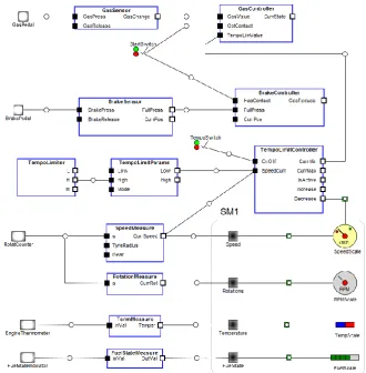
The example given below illustrates the application of action reports in the synchronization of complex services and actions in a simplified version of a car control system. The DSL that is featured in Fig. 5 was constructed starting from the Real-time Object-oriented Modeling Language (ROOM) [35], whose numerous variations are used in the automotive industry. The basic concepts of this language include objects (Actor, External client port, External server port, and Switch) and relations (Binding and Visualization). These language concepts are sufficient for describing driver’s interaction with car devices, command processing, state indications on a display, and the feedback between the current car speed and the way the system reacts on driver’s commands and states of different sensors.
The model shows a collection of external client ports, such as gas pedal, brake pedal, rotation counter, engine thermometer, and fuel state indicator. These mostly analogue devices are connected through sensors to controllers or external server ports, from which measured values are forwarded to display components (for speed, rotation, temperature, and fuel level). Switches that turn engine and cruise control (tempo limiter) on and off are connected to gas and speed controllers. This abstract model of a car control system has two units. The first unit includes objects that read values and forward them to controllers. The other unit contains objects that are used to display values. In the development of car control systems, a practitioner would have the following expectations from DSM:
to be able to extend the language and graphical representations of concepts (meta-modeling);
to be able to describe any complex control system using diagrams and to test such models (modeling);
to connect a model to analogue devices, external applications, or HMI components that support advanced graphics;
Action Reports
Fig. 5. Car control system as specified in a DSL
because these tools do not include an implementation of action report interpreters. The indirect method involves using APIs to access the repository of DSM tools with the goal of creating objects and setting property values.
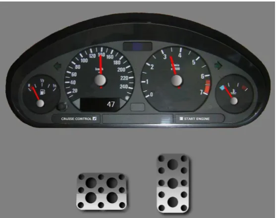
Fig. 6. HMI components as created in WPF
In Listing 4, we present a code generator for the model featured in Fig. 5. It is a MERL report that generates code for web service calls.
Listing 4. MERL report that generates web service calls
Report 'External Server Ports' $mUrl = :VusualURL;
foreach .External Server Port; {
filename :CodeTargetFolder;1 :Name; '.h' write '#ifndef C_' :Name;'_HEADER_H_' newline
'#define C_' :Name;'_HEADER_H_' newline newline
'#include "GenericServerPort.h"
class C' :Name; ' : CGenericServerPort' newline '{
public:' newline
' C' :Name; '(int mCurrVal) : CGenericServerPort(currVal) {
Action Reports
' virtual~C' :Name; '(void) { }'
newline
do ~ValueOnPort;~UsedFor;.() {
' int Get' type '() {
';
' String mUrl = "' $mUrl 'Get' type '"; }'
newline }
' void On' :Name; 'Update(int currVal) {'
newline
do ~ValueOnPort;~UsedFor;.() {
' String mUrl = "' $mUrl 'Set' type do :()
{
'?' type'=m_'type; }
'";' newline }
' };'
do ~Server~Server.() {
if :IsSensor;='T' then
newline ' C' :Name; '& m_' :Name; ';' endif
} newline
'#endif' newline close }
endreport
From the model, we generate web service addresses and HTTP GET requests that read and set the current speed. An excerpt from the code that was generated using the aforementioned report is presented in Listing 5.
Listing 5. An excerpt from the generated code for calling web services
#ifndef C_Speed_HEADER_H_ #define C_Speed_HEADER_H_ #include "GenericServerPort.h" class CSpeed : CGenericServerPort {
CSpeed(int mCurrVal) : CGenericServerPort(currVal) {
//TODO: ??? }
virtual~CSpeed(void) { }
int GetSpeedScale() {
String mUrl = "http://localhost:13216/ CarDashWebService.asmx/GetSpeedScale"; }
void OnSpeedUpdate(int currVal) {
String mUrl ="http://localhost:13216/ CarDashWebService.asmx/SetSpeedScale? ScaleName=m_ScaleName?MinValue=m_MinValue? MaxValue=m_MaxValue?Precision=m_Precision? CurrValue=m_CurrValue";
};
CSpeedMeasure& m_SpeedMeasure; #endif
7.2. Applying Action Reports to Function Block Diagrams
In this subsection, we present another practical example that highlights our experience in the application of GPLs and DSLs in measurement and control systems. The example involves using DSM tools to construct and apply a graphical language for the description of function block diagrams according to the IEC 611.31 specification [18].
Action Reports
applying DSM tools in the construction of a IEC 611.31 language,
specifying code generators and action reports using a M2T transformation language,
generating ST and native code from models; and
interpreting models where incremental updating is supported.
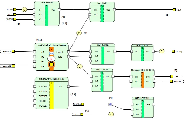
For the construction of the IEC 611.31 graphical GPL, we used the MetaEdit+ modeler. In Fig. 7, there is an example of FBD, which is further used to explain main concepts of the language. The language features objects of the following types: function block (1), type convertor (2), distributor (3), input and output connectors (4), and connectors of logical pages (5). Function block (FB) has three subtypes: built-in FB (1.1), intrinsic FB (1.2), and external FB (1.3). Each function block has ports through which it exchanges input and output values with other objects. In the process of language construction, we defined several variants of concrete graphical syntax, model constraints, and diagnostics for incorrect operations and inconsistent model states. We selected the textual IEC 611.31 (ST) and Abstract Syntax Tree (AST) to be our target languages. In line with the example from the introduction (Fig. 1), our intention was to generate GPL specifications in the IEC 611.31 ST syntax from model, together with native code for Intel and ARM processors that is optimized for the target domain, by using AST as input structure for native code generation. Since in both cases a target interpreter is required to execute a model, for that purpose we used a special RTS that executes segments of native code. As native code generation is closely related to compiler construction, to this end, we relied on various industry and academic solutions and experiences.
In Listings 6 and 7, we give short excerpts from the generator of ST code, as well as the end result related to the model in Fig. 7. Generators were written in MERL. The ST code generator iterates through all Custom FBs and checks whether they are macros. In the case they are macros, it calls a generator that retrieves the code defined by the macro. In the case they are not macros, by relying on properties, it retrieves definitions of input
(VAR_INPUT … END_VAR) and output (VAR_OUTPUT … END_VAR) signals,
as well as internal variables (VAR … END_VAR). Whenever a function block is declared as a macro, its graphical representation is changed so that a circled letter M appears in the center of the symbol (see Fig. 7). The body of the Custom FB is retrieved from the :IEC_StructText; property.
Listing 6. Excerpt from the generator of ST code
report '_IEC_CodeForCustomFB' foreach .IEC_CustomFB; {
if :IEC_IsMacro; = 'T' then do decompositions {
subreport '!IEC_STCode' run newline
} else
'FUNCTION_BLOCK ':IEC_CustomFBName; newline $p = ''
do :IEC_Inputs; {$p ='T'} if $p = 'T' then
'VAR_INPUT' newline do :IEC_Inputs; {
' ':IEC_PortName; ':' :IEC_DataType; if :IEC_Default; <> '' then
' := ' :IEC_Default; endif ';'
newline }
'END_VAR' newline endif
$p = ''
do :IEC_Outputs; {$p ='T'} if $p = 'T' then
'VAR_OUTPUT' newline do :IEC_Outputs; {
' ':IEC_PortName; ':' :IEC_DataType; if :IEC_Default; <> '' then
' := ' :IEC_Default; endif ';'
Action Reports
'END_VAR' newline endif
$p = ''
do :IEC_LocalVars; {$p ='T'} if $p = 'T' then
'VAR' newline do :IEC_LocalVars; {
' ':IEC_PortName; ':' :IEC_DataType; if :IEC_Default; <> '' then
' := ' :IEC_Default; endif ';'
newline }
'END_VAR' newline endif
:IEC_StructText; newline endif
if :IEC_IsMacro; = 'F' then
'END_FUNCTION_BLOCK' newline newline endif
}
endreport
The resulting ST code is produced by calling the generator, which translates the whole model and associated submodels. Generation of Custom FBs is only one segment of the translation process. In the generated code, after the PROGRAM keyword, there is the name of the model featured in Fig. 7, followed by the definitions of all the input and output ports or signals. Input and output signals are translated into input and output variables of the corresponding types, while external signals are translated into external variables. At the end of the code excerpt, there is the body of the ST program, which contains a description of the relations defined by the model. The code in the line Add_1_out := ADD(INT_TO_UDINT(SIG45),
SIG1, SIG18); indicates that the out port of the FB instance Add_1 is
modified by adding SIG45, SIG1, and SIG18, where SIG45 was previously converted from INT to DINT.
Listing 7. Generated ST code
PROGRAM Example_with_all_language_concepts VAR_INPUT
DstrSrc:INT; SIG1:UDINT := 7; SIG18:UDINT := 21; SIG45:INT := 10; END_VAR
SIG3:BOOL; END_VAR VAR_EXTERNAL SIG444:REAL; Sensor1:INT; Sensor2:INT; END_VAR
VAR
Abs_1_out :INT; Add_1_out :UDINT; Add_2_out :REAL; Add_Dstr_out :INT; Eq_1_out :BOOL; Mul_1_out :INT; SinusGen:GENERATOR; Custom_FB2:CFB_Commands; FanCtrl:CFB_HomeHeating; END_VAR
Add_1_out := ADD(INT_TO_UDINT(SIG45), SIG1, SIG18); Eq_1_out := EQ(Add_1_out, INT_TO_UDINT(FanCtrl.Speed)); SinusGen(1, 1.0, 5.0, 10.0, 2.0);
Add_2_out := ADD(INT_TO_REAL(FanCtrl.out2), 55.9, SinusGen.OUT);
Custom_FB2(Add_2_out, 46.0); FanCtrl(Sensor1, 9, 10, Sensor2);
Mul_1_out := MUL(FanCtrl.Speed, FanCtrl.out2, 40); Abs_1_out := ABS(Mul_1_out);
AbsSig := INT_TO_USINT(Abs_1_out); SIG3 := Eq_1_out;
Add_Dstr_out := ADD(DstrSrc, DstrSrc, REAL_TO_INT (Custom_FB2.out1));
SIG444 := Custom_FB2.out2;
END_PROGRAM
By constructing the language and using the IEC 611.31 ST generator, we have achieved two important goals that can be accomplished neither by modeling tools that focus only on FBDs nor by UML tools. The first goal was to construct a language that could be easily transformed into a DSL in order to satisfy some domain-specific requirements. The second goal was to transform abstract models into an arbitrary target language, as well as into native code, For some FBs, it is possible to generate code according to some syntax, e.g., to that of VHDL, that would initialize wired-logic controllers. In Fig. 7, such a FB is shown with a processor symbol in the middle. Submodels of a model are transformed into even more different languages. Since DSM tools do not support explicit declaration of a submodel, we achieved this by introducing the IsWired property to FBs and writing a generator that utilizes that property.
Action Reports
Numerous tools support model verification but only for complete specifications. Our approach is based on the following idea: each specification, from an empty model to the most complex specification, should be interpreted simultaneously with the modeling process. We refer to such model execution as the interpretation with incremental updating. Similar approaches may be found within simulation tools, such as Simulink [36] or LabView [23]. However, in those cases, the semantics of a modeling language is fixed in advance, which significantly simplifies the whole process. Because of the restrictions associated with language construction, model execution using these tools cannot be considered as a full-fledged MeMID activity.
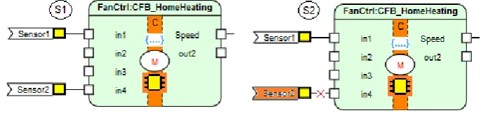
Fig. 8. Incremental update of a MCS
In the rest of this section, we present a practical example of using incremental updating and action generators in a typical MeMID activity. In Fig. 8, two states of a model for fan control, S1 and S2, are depicted as submodels of the model featured in Fig. 7. The state of the model S1
corresponds to the state of a real system when Sensor 1 (T1) is functioning normally. The state of the model S2 corresponds to the state of the real system when sensor T1 is being repaired or replaced. This is the case when a problem with rotation speed of a fan may occur due to a thermometer malfunction. In the model, thermometer replacement is defined as a complex transaction that is made of various MeMID activities. It is also possible for an external application that is synchronized with the model or interpreter to display an image which shows that the installation is in progress. Sensor change is recorded in a document that contains information about the location, time, and identifier of the replaced sensor. In order to better understand the example featured in Fig. 8, it may be worth consulting the specification of function block diagrams in accordance with the IEC 611.31 specification [18] and watching a video clip [9] that demonstrates the construction of a DSL and model execution in a target interpreter.
According to the MeMID scenario, a sensor replacement procedure and documenting of the replacement include the following actions:
An action report that simulates the replacement is executed. It changes the model from state S1 to state S2 and sets an appropriate image in a client application.
Sensor 1 (T1) is detached from the function block and a default value that corresponds to the temperature which is measured by some other thermometer is assigned to the input i1 (i1=21°C). The transaction is then confirmed by the model. Using this information, a code update is generated for a target interpreter. This update is only an increment and not a complete program.
A service person replaces the sensor.
In the simulator, the model changes to the previous state and checks the functioning of a new sensor (Sensor 1 is reattached to i1).
The model is connected to the real system and returns to interpreting from the previous state.
An action report that generates the documentation about the changes in the system during sensor replacement is executed.
Documenting model changes, as a part of the MeMID activity, is partially covered in the example featured in Section 5. When action reports are used in documenting results of the testing of a MCS, they retain a similar structure. They feature nested commands that contain a DSL script or functions which return document content increment.
The aforementioned examples illustrate one advanced scenario of applying DSM tools in specialized production environments. While DSM tools support meta-modeling and modeling well, when it comes to the transformation of submodels to certain target languages, their use in complex MCSs is limited. The main reason is the way how they synchronize with external applications and their poor support for logical connection of actions in a real system to operations on models. General purpose DSM tools are less user-friendly for modeling when compared to specialized CASE tools or applications for modeling measurement and control systems. Efficient use of DSM tools also requires improvement of their graphical interfaces. In the following section, these improvements are described as user operations on models.
8.
Action Reports and Operations on Model
Action Reports
Using action reports for formal specification and implementation of three groups of operations constitutes the basis for the improvement of DSM tools. The first group includes operations that accelerate the construction of a DSL and different visual representations of language concepts in a DSM tool by relying on the existing user HMI components. The second group includes operations used to define the behavior of the graphical interface for basic user operations: insert, delete, connect, disconnect, update, move, etc. The third group includes operations on submodels. With some minor extensions, navigation languages for M2T transformations could support all three groups of operations.
The general structure of reports used to define operations of the first group, i.e., those used to transfer a part of the definition of an external HMI component to a meta-model, is presented in Listing 8. As previously discussed, the DSM tool and user application need to include instances of an action report interpreter capable of interpreting specified actions.
Listing 8. General structure of reports defining operations that transfer definitions of external HMI components to meta-models
ACTION_BEGIN
ObjectDef | RelDef | RoleDef | PropDef ACTION_END
Operations used to define the behavior of the graphical interface should provide expected spatial arrangement of model elements during all kinds of user actions. One method of defining the behavior of a graphical interface is to apply structural patterns in the way that we used them to define document layout. In Listing 9, we present only some of the typical patterns, while a more detailed description of grammar rules and examples may be found in [14]. Each pattern consists of an ordered (OL) or unordered list (UL) of elements, which represent objects and relations in a DSM model. Validation or customization of the model according to the specified patterns is performed during the execution of user operations (insert, delete, connect, etc.). Semantic actions that perform validation according to the patterns are executed using action reports. During this process, rules of spatial layout and structural rules are translated into topological properties of model elements.
Listing 9. Pattern examples
PATTERN A UL(B,C,D) END
// The A element consists of three elements, which may appear in any order.
PATTERN A OL(B,C,D) END
// The A element consists of three elements, which may appear only in the specified order.
PATTERN A UL(B,C,D) isLeftOf(C,D) END
PATTERN A UL(B,C,D) isLeftOf(C,D) isBelow(D,B) END
// The A element consists of three elements, but the C element must appear to the left of the D element while the D element must appear above the B element.
PATTERN A UL(B,C[3..5],D) END
// The B element appears exactly once, the C element appears from three to five times, while the D element appears exactly once. The elements may appear in any order.
PATTERN A OL(B*,OL(C,D)) END
// The B elements must appear first for any number of times, followed by the C element and the D element, respectively. PATTERN A UL(B*,C*,D*) END
// The elements B, C, and D may appear for any number of times in any order.
The third group of operations, whose semantics may be expressed through action reports, is used to: (i) construct submodels and carry out all operations on (sub)models without the need for the execution of low-level API functions on the repository; and (ii) define transactions.
The construction of submodels and corresponding operations is similar to the definition of views in relational databases or the definition of complex objects in object databases. We focus on operations that could significantly improve MeMID activities when the modeling tool is linked to the target interpreter via action reports. Therefore, we give an overview of the selected operation set:
CreateSubmodel (listOfElems) – creates a submodel based on the specified list of objects, connections, relations, roles, and properties from an existing model;
SetCurrentSubm (m_ID) – sets one of the defined submodels as the current one;
DeleteSubmodel (m_ID) – deletes the submodel definition;
AddModel (m_1,m_2) – joins two submodels into one without modifying any relations;
Subtract (m_1,m_2) – removes m_2 from the existing composite model
m_1;
Multiply (m_1,n) – creates a new model by repeating the model m_1 n
times;
Intersection (m_1,m_2) – returns a model containing intersecting element from m_1 and m_2;
Union (m_1,n) – joins two models without repeating elements having same identifiers;
SimDifference (m_1,m_2) – finds a symmetric difference between the two
models;
Remove (objType|relType) – removes objects or relations of the specified
type from the submodel; and
Action Reports
We used DVDocIDE, a DSM tool for document modeling, to test usage of action reports and patterns as means of a more efficient DSM modeling of documents and their templates. We used DVQL [25], a command/query language for documents, to implement operations on submodels. In order to verify usefulness of these operations in general purpose DSM tools, the latter should be considerably extended. This issue is also one of the topics of our future research.
9.
Related Work
Over the last few years, Executable UML has been a recurring topic in both the academic and engineering community [32]. Numerous papers and practical solutions extend its usability for simulations and model execution [17], [23], [36]. However, it seems that the transfer of very narrow specialized knowledge to web services (Cloud computing) is advancing more rapidly as opposed to the use of UML tools for the domain-specific problems. In the academic community, much of the model transformation research relies on the OMG’s specification Query/View/Transformation (QVT) [28]. The specification consists of three interrelated languages: (i) Relations, (ii) Core and (iii) Operational Mapping. Atlas Transformation Language (ATL) [2] by the Eclipse Foundation [15] is an example of a model-to-model (M2M) transformation language in accordance with the QVT standard. Among the commercial tools, one of the best known transformation languages is MetaEdit+ Reporting Language (MERL) [30]. It is a language mainly focused on model-to-text (M2T) transformations. It partially supports transformations that conduct synchronization between the model, client applications, and target interpreter. By minimally extending MERL to allow specification and interpretation of action reports, it would be possible to synchronize applications that feature disparate user interfaces, and target interpreters or “execution machines” [1], [4], [6], [24], [31], [38].
In [20] and [27], the authors present ideas and solutions for domain-specific model transformations and debugging. Our consideration of code generators differs slightly from the one presented in [20]. We believe that template-based M2T transformations are complex, insufficiently flexible, and complicated to be implemented within the HMI components and target interpreter of models.
necessity of the use of transactions and logging of all model changes for the purpose of backtracking. They resolve the issue of the synchronization between a model and the execution engine by relying on the concurrent access to configuration files used by the DSM editor and execution machine. From their simple example implemented using Eclipse EMF, it seems that the application of their idea is limited to less complex cases. In our approach, which is based on the use of M2T transformations, there are slight extensions of existing navigational languages for M2T transformations and two logically independent execution engines: a report interpreter and a target interpreter of models.
In [37], the authors describe the OMG’s approach to standardization of UML model execution, which involves using Action Semantics, i.e., explicit definition of execution rules at the level of the UML meta-model. The goal of this standardization is to allow: (i) software independent specification of actions on UML models; and (ii) execution of UML models. Their approach is based on the following three abstractions: meta-model, execution model (UML model), and actions. The semantics of actions is defined, but not the concrete syntax, because it depends on the target language used in code generation from a model. Because this approach requires knowledge about UML meta-modeling, it seems unlikely that it will be widely applied in domain specific problems, particularly for modeling measurement and control systems.
Among numerous tools for modeling measurement and control system that may be used in the extension of DSM tools, or for better illustration of action reports and use of modeling tool as client applications, the following two stand out: Simulink [36] and IbaLogic [17]. Simulink is a tool primarily aimed at drawing function block diagrams. It features a large library of function blocks that may be customized and supports generation of source code in the C language. In the context of the MeMID activities, Simulink does not adequately support meta-modeling and generation of documentation about model execution. IbaLogic is a tool for modeling measurement and control systems that employs structured text and function block diagrams according to the IEC 611.31 specification, where a function block model is also an execution model. This tool supports linking to various run-time systems that may interpret or execute a model. However, meta-modeling and code generation for different programming languages are not supported. Owing to the featured implementation of a set of basic operations on models, it supports: (i) every version of the incremental update for a target system during interpretation; and (ii) visualization of the state of a real system within the modeling tool.
10. Conclusion
Action Reports
better automate the MeMID activities: meta-modeling, modeling, testing of models, generated code, and interpreter, and generation of documentation about test cases. In the areas of document engineering and development of measurement and control systems, the action report approach allows us to specify the following procedures within abstract models: (i) the process of documenting model validation; and (ii) in the context of certain business rules and procedures, the synchronization of actions on a model to the state of the real system. Owing to this, action reports are especially effective when combined with DSM tools that, instead of relying on patterns, conduct M2T transformations by using a dedicated target language and interpreter. In production systems where business procedures are specified both precisely and formally, there is also a need to document each action on the model or to execute each action on the model by relying solely on the previously generated and authorized document. By using action reports, it is possible to synchronize not only the different components that are part of the MeMID activities but also the heterogeneous business and control processes, which feature complex business rules and operation of arbitrary control systems.
Our future research directions include: (i) construction of a language for the description of constraints on presentation elements (graphs), which in turn would simplify the customization of meta-modeling and modeling tools for different domains of application; (ii) construction of M2T transformations, i.e., code generators that would produce binary or assembly code for different processors by starting from abstract models; and (iii) conceptualization of run-time systems that would interpret abstract models, which in turn would be transformed into different target languages, software logic or wired logic. The ultimate goal of our research is to support, to the greatest extent possible, the MeMID scenario, which consists in using modeling tools as client applications to manage business and control processes. The approach presented in this paper was created to be focused on the domain of application and provide pragmatic support to users. For these reasons, its application capabilities may not be fully generic. However, the goal of developing the approach is not primarily oriented to this end, but to provide the foundation for a quality support to users in the domain of monitoring the measurement and control processes. At present, our approach supports modeling and executing models of measurement and control systems. We expect that our ideas, examples, and practical solutions presented in this paper are going to contribute to a better use of DSM tools as client applications for the monitoring of measurement and control processes.