INTERNATIONAL JOURNAL OF ENGINEERING SCIENCES & MANAGEMENT 1
I
NTERNATIONAL
J
OURNAL OF
E
NGINEERING
S
CIENCES &
M
ANAGEMENT
ANALYSIS AND DESIGN OF A MULTI STORIED BUILDING WITH SHEAR WALL
BY USING STAAD PRO
Khaja Begum**Dept. of Civi Engineering, JPNCE college of Engineering, Mahbubnagar
ABSTRACT
In present scenario buildings with shear wall is a typical feature in the modern multi-storey construction in urban India. Such features are highly undesirable in building built in seismically active areas. This study highlights the importance of explicitly recognizing the presence of the shear wall in the analysis of building. Design of RCC elements will also be performed as per IS: 456-2000 and IS: 13920-1993 for the building with shear wall.
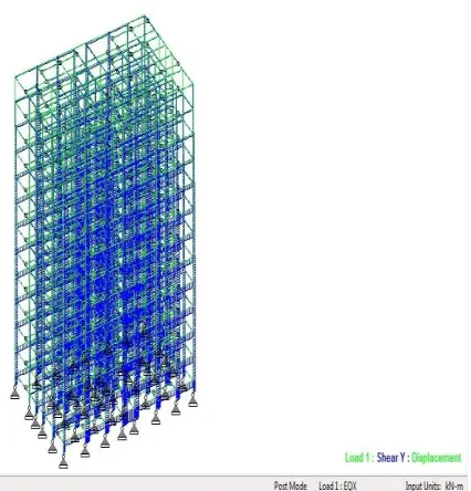
A numerical study will perform using Staad pro. Software will be used for 3D multi storey frames with shear wall to study the responses of the structure under seismic and wind loads. Shear force, Bending moment, axial force, inter storey drift, base shear, storey shear, storey moment will be computed for buildings with shear wall.
Keywords: Shear wall, Inter storey drift, Base shear, Storey shear, Storey moment.
I. INTRODUCTION
Many rise buildings have been constructed in different cities of the world. The trend of construction of high-rise buildings for both office & residential purposes is rapidly increasing. The main reasons for this trend are the increase in population densities due to urbanization, the growth of population and the high cost of land in urban areas. The economic prosperity and the technological advancement are also part responsible for the evolution of tall buildings. In many cases, tall buildings evolve as prestige symbols for commercial enterprises and organizations.
Although the construction of high-rise buildings has solved the problem of usable space in urban areas, it has caused many environmental and psychological social problems. The construction of high-rise buildings in the neighborhood of low-rise dwellings may spoil the urban aesthetics. It can also aggravate traffic problems if the location does not fit into the existing planning of the city. Closely spaced high-rise buildings may also cause pollution problems and obstruct sunlight, to the adjacent properties. A child brought up in high-rise buildings has less chance to explore and manipulate the environment. This may adversely affect the psychological development of the child in future years. The inhabitants of high-rise buildings often exhibit greater feelings of indifference and withdrawal towards neighbors. This is in contrast to dwellers of low-rise houses. The crime rate in high-rise buildings is higher compared to relatively low rise buildings. These are some of the problems for which the high-rise buildings are criticized in recent times.
INTERNATIONAL JOURNAL OF ENGINEERING SCIENCES & MANAGEMENT 2
Buildings are the important indicator of social progress of the county. Every human hasdesire to own comfortable homes on an average generally one spends his two-third life times in the houses. The security civic sense of the responsibility. These are the few reasons which are responsible that the person do utmost effort and spend hard earned saving in owning houses.
Now a day the house building is major work of the social progress of the county. Daily new techniques are being developed for the construction of houses economically, quickly and fulfilling the requirements of the community engineers and architects do the design work, planning and layout, etc, of the buildings. Draughtsman is responsible for doing the drawing works of building as for the direction of engineers and architects. The draughtsman must know his job and should be able to follow the instruction of the engineer and should be able to draw the required drawing of the building, site plans and layout plans etc, as for the requirements.
II. LITERATURE SURVEY
When the shear walls are arranged in a symmetric manner in the plan of the building, wind and seismic loads will cause translational displacements only. In these cases, the deformation of the building confined to a plane and the load-displacement behavior of the structure can be described by a two-dimensional analysis. The common examples of symmetric buildings are the apartment buildings with two-parallel sets of regularly spaced shear walls. In such cases, the behavior of the whole building can be studied from the two-dimensional behavior of a typical pair of shear walls. The shear walls may be coupled either through the floor slabs or floor beam or both. This class of problem is generally known as the plane coupled shear walls problem. The analysis of uniform plane coupled shear walls subjected to static loading has been presented by Chitty, Beck, Eriksson and Rosman. Sets of design curves for a few common loading cases are presented by Coull and Choudhurry. Extensions to cover the cases with non-uniform shear walls are reported by Burns, Coull and Puri, Traum, Rosman & Tso and Chan. The effect of the flexibility of foundation on the coupled shear walls is included in studies by Coull, Tso and chan. The inelastic behaviour of the plane coupled, shear walls has been studied by Winokur and Gluck Pauley.
The dynamic properties of the coupled shear, has been studied. An approximate seismic analysis, based on the response spectrum technique is presented by Tso and Biswas. The multiple bay planar shear walls have been treated by Hussein EIkholy and Robinson and Coull and Subedi. The methods of analysis mentioned above employed continuous approach which replaces the connecting beams between the walls by a continuous distribution of laminae of equivalent stiffness. Coupled shear walls can also be analyzed as equivalent frames using standard matrix structural analysis techniques. The typical examples of this approach are the works of candy, Mc Leod, Schwaignofer and Microys and Stafford Smith. The finite width of the shear wall is accounted for by assuming sets of infinitely rigid beams connected to the column of the equivalent frame. The length of the rigid beam is taken from the centerline to the edge of the shear wall. The finite element idealization has been proposed by MacLeod and Butlin and McMillan. A solution of coupled shear walls by the continuous approach, the equivalent frame method and the finite element method has been compared by Choudhurry. Essentially, the three approaches give the same
results for the cases studied.
When symmetry does not exist in the plan of the building the lateral loads will cause twisting of the building in addition to translation. Out-of-plane displacements exist in this case. A two-dimensional approximation becomes in adequate in determining the structural behavior of the building and a three-dimensional analysis will be necessary. A review of the methods of three dimensional analyses of high rise buildings is presented by Stafford Smith and Stamato.
INTERNATIONAL JOURNAL OF ENGINEERING SCIENCES & MANAGEMENT 3
sections. A similar approach with a finite element idealization for transverse stiffness of the floor slab was used by Taranath. An approximate method of analysis of building structures consisting of parallel system of shear walls and box cores was presented by coull and Irwin. The continuous approach has been used to determine the flexibility of wall units. The analysis of the complete structure is then performed by combining the stiffness of different portions of building. Another approximate method for buildings consisting of two dimensional panels was presented by Stamato and Stafford Smith.
III.
ARCHITECTURAL ASPECTS OF SHEAR WALLSMost RC buildings with shear walls also have columns, these columns primarily carry gravity loads (i.e.those due to self-weight and contents of building) shear walls provide large strength and stiffness to buildings in the direction of their orientation which significantly reduces lateral sway of the building and thereby reduces damage to structure and its contents. Since shear walls carry large horizantal earthquakeforces, the overturning effects on them are large. Thus, design of their foundations requires special attention. Shear walls should be provided along preferably both length and width. However, if they are provided along only one direction, a proper grid of beams and coloumns in the vertical plane (called a moment-resistant frame) must be provided along the other direction to resist strong earthquake effects. Door or window openings can be provided in shearwall, but their size must be small to ensure least in interruption to force flow through walls. Moreover, openings should be symmetrically located. Special design checks are required to ensure that the net cross-sectional area of a wall at an opening is sufficient to carry the horizontal earthquake force. Shear walls in buildings must be symmetrically located in plan to reduce ill-effects of twist in buildings (Figure 4). They could be placed symmetrically along one or both directions in plan.Shear walls are more effective when located along exterior perimeter of the building – such a layout increase resistance of the building to twisting.
The primary purpose of all kinds of structural systems used in the building type of structures is to support gravity loads. The most common loads resulting from the effect of gravity are dead load, live load and snow load. Besides these vertical loads, buildings are also subjected to lateral loads caused by wind, earthquake. Lateral loads can develop high stresses, produce sway movement or cause vibration. Therefore, it is very important for the structure to have sufficient strength against vertical loads together with adequate stiffness to resist lateral forces.
In India a considerable number of buildings have reinforced concrete structural systems. This is due to economic reasons. Reinforced concrete building structures can be classified:
1. 1. Structural Frame Systems: The structural system consists of frames. Floor slabs, beams and columns are the basic elements of the structural system. Such frames can carry gravity loads while providing adequate stiffness.
2. Structural Wall Systems: In this type of structures, all the vertical members are made of structural walls, generally called shear walls.
3. Shear Wall–Frame Systems (Dual Systems): The system consists of reinforced concrete frames interacting with reinforced concrete shear walls.
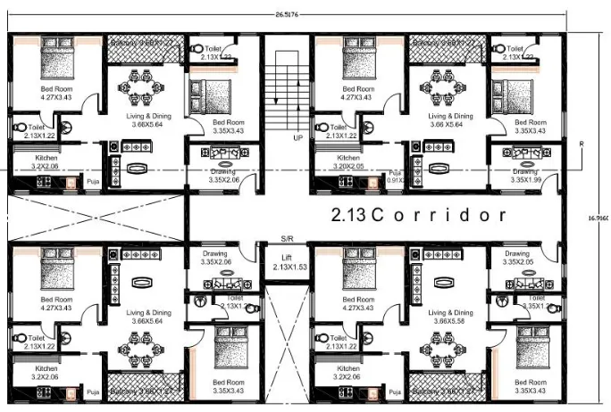
4. Most of the residential reinforced concrete buildings structures in India have shear wall-frame systems. A typical floor plan of a shear wall-frame building structure is given in Figure 1. It is a fact that shear walls have high lateral resistance.
INTERNATIONAL JOURNAL OF ENGINEERING SCIENCES & MANAGEMENT 4 Figure 3.1 Typical Floor Plan Of A Shear Wall - Frame Building Structure
Construction Of RC Shear Wall
IV. TECHNICAL APPROACH
Parameters Considered
1. Geometry
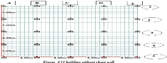
1. Length of Building : 26.517 m
2. Width : 16.916 m
3. Height : 45m
4. No of storey’s : 14
5. No of bays in X-direction : 7 no. 6. No of bays in Y-direction : 8 no.
2. Properties
1. Column size : 0.45 m x 0.50 m, 0.5 x 0.6 m, 0.6 x 0.6 m
2. Beam size : 0.45m x 0.30m, 0.30m x 0.23m
3. Shear Wall Thickness : 180 mm
4. Type of construction : R.C.C framed structure
INTERNATIONAL JOURNAL OF ENGINEERING SCIENCES & MANAGEMENT 5
6. Thickness of outer walls : Brick Masonry 230mm thick duly plastered for External walls
7. Thickness of inner walls : Brick Masonry 115mm thick duly plastered for Internal walls
8. Ground floor : 3m
9. Floor to floor height : 3m.
10. Height of plinth : 0.6m from existing ground level 11. Depth of foundation : 1.5 m below ground level
12. Roof covering : RCC Slab
13. Foundation : Open Foundation Isolated RCC Footing
14. Edge / end conditions : Pinned connection framed, Structure slabs are rigidly connected to beams, and Beams are
rigidly connected to column 3. Materials
1. Concrete grade : M30 for Columns, Beams, Slabs & Footings
2. All steel grades : Fe415 grade
3. Bearing capacity of soil : 400KN/m²
4. Standard Dimensions Of Residential Rooms
Maximum floor area for drawing room is 20-28 sq.mts and minimum is 13.5 sq.mts Maximum floor area for dining room is 17-20 sq.mts and minimum is 10 sq.mts Maximum floor area for bed room is 15-25 sq.mts and minimum is 11 sq.mts Maximum floor area for office room is 7-9 sq.mts and minimum is 6.5 sq.mts Maximum floor area for kitchen is 7-9 sq.mts and minimum is 5.5 sq.mts Maximum floor area for guest room is 9-10.5 sq.mts and minimum is 7 sq.mts Maximum floor area for store room is 7-9 sq.mts and minimum is 5.5 sq.mts Maximum floor area for dressing room is 4-7 sq.mts and minimum is 5.5 sq.mts Maximum floor area for bath & water closet is 4.5 sq.mts and minimum is 2.8 sq.mts Maximum floor area for bath room is 3.5 sq.mts and minimum is 2.5 sq.mts
Maximum floor area for carriage is 15-18 sq.mts and minimum is 11 sq.mts Maximum floor area for veranda is 2.5-3.0 sq.mts and minimum is 1.5 meters wide
INTERNATIONAL JOURNAL OF ENGINEERING SCIENCES & MANAGEMENT 6
5. Software Used
Introducing staad pro. V8
Our project involves analysis and design of multi-storied [UG+G + 12] building using a very popular desigining software STAAD Pro. We have chosen STAAD Pro because of its following advantages
o easy to use interface,
o conformation with the Indian Standard Codes, o versatile nature of solving any type of problem, o Iv) Accuracy of the solution.
STAAD.Pro features a state of the art user interface, visualization tools, powerful analysis and design engines with advanced finite element and dynamic analysis capabilities. From model generation, analysis and design to visualization and result verification, STAAD.Pro is the professional’s choice for steel, concrete, timber, aluminium and cold-formed steel design of low and high rise building, culverts, petrochemical plants, tunnels, bridges, piles and much more.
6. Codal Provisions
IS: 456-2000 Plain and Reinforced Concrete - Code of Practice
IS 875: Part 1: 1987 Code of practice for design loads (other than earthquake) for buildings and structures Part 1 Dead loads - Unit weights of building material and stored materials (Incorporating IS: 1911-1967)
IS 875: Part 2: 1987 Code of practice for design loads (other than earthquake) for buildings and structures: Part 2 Imposed loads
IS 875: Part 3: 1987 Code of Practice for Design Loads (Other than Earthquake) for Buildings and Structures - Part 3: Wind Loads
IS 875: Part 5: 1987 Code of practice for design loads (other than earthquake) for buildings and structures Part 5 Special loads and load combinations
SP 16: 1980 Design Aids for Reinforced Concrete to IS 456: 1978
IS 13920: 1993 Ductile detailing of reinforced concrete structures subjected to seismic forces - Code of practice
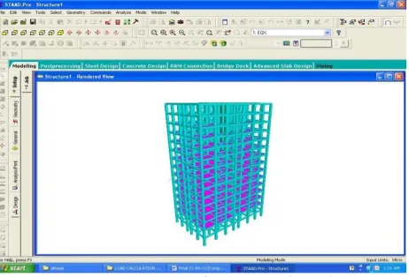
Figure 4.2 Generation Of Structure Through Gui
7. Loads Considered
Dead Loads
As per IS: 875-Part 1
Loads from cantilever slabs i.e. = WLx
Weights due to walls on beam = (3 x 0.23 x 20) = 13.8 KN/m
INTERNATIONAL JOURNAL OF ENGINEERING SCIENCES & MANAGEMENT 7
Calculation of DL on slab
Self weight of the slab = 0.15 x 25 = 3.75 kN/m² Floor finish on the slab = 1.0 kN/m² --- Total = 4.75 KN/m² ---
Wall load
For 230 mm thick 0.23*2.7*19 = 11.89 ≈ 12 KN/m
For 115 mm thick 0.115*2.7*19 = 5.945 = 6 KN/m
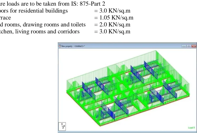
Figure 4.3 Dead Loads Udl Showing On Inner Walls
Live Loads
As per IS: 875-Part 2
Live Load On Beams
This is the live loads of slab which comes on beams in form of triangular or trapezoidal variation.
Live Load On Slab
This are loads are to be taken from IS: 875-Part 2
On floors for residential buildings = 3.0 KN/sq.m
On terrace = 1.05 KN/sq.m
On bed rooms, drawing rooms and toilets = 2.0 KN/sq.m On kitchen, living rooms and corridors = 3.0 KN/sq.m
INTERNATIONAL JOURNAL OF ENGINEERING SCIENCES & MANAGEMENT 8 Figure4.5 Live Load-Udl Showing On Outer Walls
Seismic Loads As per IS: 1893-2002
Base shear = ah X w
ah = (Z/2) X (I/R) X (Sg/g)
Where, ah = Design horizontal acceleration spectrum value Z = Zone factor for MCE conditions R = Response reduction factor
Sg = Spectrum acceleration depending upon period of vibration and damping
g = Acceleration due to gravity
• Z= zone factor for Hyderabad is zone 2 = 0.1
• Importance factor I = 1 for our structure
• Response reduction factor R = 3
• Tx = [ 0.09 X h/ (d0.5) ] , TM = [ 0.09 X h/ (d0.5) ]
Where, Px and Pz are time periods (as per IS 1893 clause 7.6.2) ‘h’ is height of structure
‘d’ is dimension of structure in that direction
After calculation we get
Px= 0.472 sec, Py= 0.744 sec
We get the value of Sa/g from graph based on time periods (figure 2, page 16) we get value as 2.5
Finally ah value can be calculated ah = 0.0417
• W= seismic weight
• The seismic weight include the dead weight of the building and reduced live load on the building
• For calculating the design seismic forces of the structure, the imposed loads on roof need not be considered (as per clause 7.3.2 pg 17)
• Damping ratio was taken as 5%
INTERNATIONAL JOURNAL OF ENGINEERING SCIENCES & MANAGEMENT 9 Figure 4.6 Earthquake Load Udl Showing On Typical Floor
Wind loads
Design wind speed Pz = 0.6 Vz2
Vz = Vb x k1 x k2 x k3 (as per clause 5.3)
Here Vb = basic wind speed m/sec
k1 = probability risk factor (from table 1)
k2 = depends terrain height and structure height factor (from table2) k3 = depends on topography (clause 5.3.3.1)
Basic wind speed for Hyderabad region = 44 m/sec ( clause 5.2) For all general buildings K1 = 1
As per clause 5.3.2.1 our structure fall under terrain category 3 and class B Pressure intensity = 0.6 Vz ² (as per clause 5.4 )
So we calculated the pressure intensity at different heights of our structure from the above relation ….
Pressure = 1.11 kN / m² at 9 m 1.25 kN / m² at 18m
1.32 kN / m² at 24 1.40 kN / m² at 30m 1.46 kN / m² at 36 m
We calculated the c/c of the column in both the direction
Pressure intensity x c/c distance = load per unit length acting on different heights
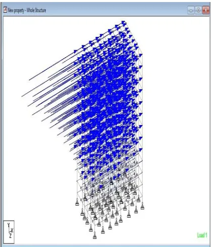
INTERNATIONAL JOURNAL OF ENGINEERING SCIENCES & MANAGEMENT 10 Figure 4.8 Wind Loads Shown In Positive Z-Direction On Typical Floor
Bending Moment
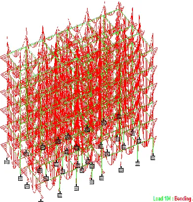
INTERNATIONAL JOURNAL OF ENGINEERING SCIENCES & MANAGEMENT 11 Figure 4.10 Showing Bending Moment Of The Beams
8. Load Combinations
Factored Load Combination o 1.5(DL+LL) o 1.2(DL+LL+EQX) o 1.2(DL+LL-EQX) o 1.2(DL+LL+EQZ) o 1.2(DL+LL-EQZ) o 1.2(DL+LL+WX) o 1.2(DL+LL-WX) o 1.2(DL+LL+WZ o 1.2(DL+LL-WZ) o 1.5(DL+EQX) o 1.5(DL-EQX) o 1.5(DL+EQZ) o 1.5(DL-EQZ) o 1.5(DL+WX) o 1.5(DL-WX) o 1.5(DL+WZ) o 1.5(DL-WZ) o 0.9DL+1.5EQZ o 0.9DL-1.5EQZ o 0.9DL+1.5WX o 0.9DL-1.5WX o 0.9DL+1.5WZ o 0.9DL-1.5WZ
Unfactored Load Combination
o DL+LL
o DL+LL+EQX
o DL+LL-EQX
INTERNATIONAL JOURNAL OF ENGINEERING SCIENCES & MANAGEMENT 12 o DL+LL-EQZ
o DL+LL+WX
o DL+LL-WX
o DL+LL+WZ
o DL+LL-WZ
o DL+EQX
o DL-EQX
o DL+EQZ
o DL-EQZ
o DL+WX
o DL-WX
o DL+WZ
o DL-WZ
Shear wall systems are one of the most commonly used lateral load resisting systems in high-rise buildings. Shear walls have very high in plane stiffness and strength, which can be used to simultaneously resist large horizontal loads and support gravity loads, making them advantageous in many structural engineering applications. There are lots of literatures available to design and analyze the shear wall .However, the decision about the location of shear wall in multistory building is not much discussed in any literatures .In this paper; therefore, main focus is to determine the solution for shear wall location in multistory building. A RCC building of six storey placed in NAGPUR subjected to earthquake loading in zone-II is considered. An earthquake load is calculated by seismic coefficient method using IS 1893 (PART–I):2002. These analyses were performing educing STAAD Pro. A study has been carried out to determine the strength of RC shear wall of a multistoried building by changing shear wall location. Three different cases of shear wall position for a 6 storey building have been analyzed. Incorporation of shear wall has become inevitable in multi-storey building to resist lateral forces .Generally shear wall can be defined as structural vertical member that is able to resist combination of shear, moment and axial load induced by lateral load and gravity load transfer to the wall frin clude lift wells or shear walls, are the usual requirements of Multi Storey Buildings6
V. ANALYSIS
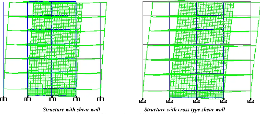
Analysis of building is done using STAAD Pro. The models were prepared in the STADD Pro. Software by using different cross sections of RC shear wall viz. Box type, L type and cross type shear wall and these are located at different location such as along periphery, at corner and at middle positions.
INTERNATIONAL JOURNAL OF ENGINEERING SCIENCES & MANAGEMENT 13 Figure: Different Model Of Building With Different Type Of Shear Wall
INTERNATIONAL JOURNAL OF ENGINEERING SCIENCES & MANAGEMENT 14 Structure with shear wall Structure with cross type shear wall
Figures: Different Types Of Structural Shearwall
VI. DESIGN OF STRUCTURAL ELEMENTS
Design of Beams
Figure Ground Floor Beams
=================================================================
B E A M NO. 999 D E S I G N R E S U L T S
M30 Fe415 (Main) Fe415 (Sec.)
LENGTH: 4500.0mm SIZE:300.0 mm X 450.0 mm COVER: 25.0 mm
SUMMARY OF REINF. AREA (Sq.mm)
INTERNATIONAL JOURNAL OF ENGINEERING SCIENCES & MANAGEMENT 15
SECTION 0.0 mm 1125.0 mm 2250.0 mm 3375.0 mm 4500.0 mm
---
TOP 533.43 257.46 257.46 257.46 681.03
REINF. (Sq. mm) (Sq. mm) (Sq. mm) (Sq. mm) (Sq. mm)
BOTTOM 257.46 257.46 261.20 257.46 257.46
REINF. (Sq. mm) (Sq. mm) (Sq. mm) (Sq. mm) (Sq. mm)
---
SUMMARY OF PROVIDED REINF. AREA ---
SECTION 0.0 mm 1125.0 mm 2250.0 mm 3375.0 mm 4500.0 mm
---
TOP 5-12í 3-12í 3-12í 3-12í 7-12í
REINF. 1 layer(s) 1 layer(s) 1 layer(s) 1 layer(s) 1 layer(s)
BOTTOM 3-12í 3-12í 3-12í 3-12í 3-12í
REINF. 1 layer(s) 1 layer(s) 1 layer(s) 1 layer(s) 1 layer(s)
SHEAR 2 legged 10í 2 legged 10í 2 legged 10í 2 legged 10í 2 legged 10í
REINF. @ 150 mm c/c @ 150 mm c/c @ 150 mm c/c
@ 150 mm c/c @ 150 mm c/c
---
SHEAR DESIGN RESULTS AT DISTANCE d (EFFECTIVE DEPTH) FROM FACE OF THE SUPPORT
SHEAR DESIGN RESULTS AT 715.0 mm AWAY FROM START SUPPORT VY =67.76 MX = -0.44 LD=50
Provide 2 Legged 10@ 150 mm c/c
SHEAR DESIGN RESULTS AT 715.0 mm AWAY FROM END SUPPORT
VY =-71.46 MX =-0.39 LD= 59
Provide 2 Legged 10í @ 150 mm c/c
===============================================================
B E A MN O. 1000 D E S I G N R E S U L T S
M30 Fe415 (Main) Fe415 (Sec.)
LENGTH:3890.0mm SIZE:300.0 mm X 450.0 mm COVER: 25.0 mm
SUMMARY OF REINF. AREA (Sq.mm)
---
SECTION 0.0 mm 972.5 mm 1945.0 mm 2917.5 mm 3890.0 mm
---
TOP 293.77 257.46 257.46 257.46 612.22
REINF. (Sq. mm) (Sq. mm) (Sq. mm) (Sq. mm) (Sq. mm)
BOTTOM 257.46 257.46 257.46 257.46 257.46
REINF. (Sq. mm) (Sq. mm) (Sq. mm) (Sq. mm) (Sq. mm)
---
SUMMARY OF PROVIDED REINF. AREA ---
SECTION 0.0 mm 972.5 mm 1945.0 mm 2917.5 mm 3890.0 mm
INTERNATIONAL JOURNAL OF ENGINEERING SCIENCES & MANAGEMENT 16
TOP 3-20í 3-20í 3-20í 3-20í 3-20í
REINF. 1 layer(s) 1 layer(s) 1 layer(s) 1 layer(s) 1 layer(s)
BOTTOM 3-12í 3-12í 3-12í 3-12í 3-12í
REINF. 1 layer(s) 1 layer(s) 1 layer(s) 1 layer(s) 1 layer(s
SHEAR s2 legged 10í 2 legged 10í 2 legged 10í 2 legged 10í 2 legged 10í
REINF. @ 150 mm c/c @ 150 mm c/c @ 150 mm c/c
@ 150 mm c/c @ 150 mm c/c
---SHEAR DESIGN RESULTS AT DISTANCE d (EFFECTIVE DEPTH) FROM FACE OF THE SUPPORT
SHEAR DESIGN RESULTS AT715.0 mm AWAY FROM START SUPPORT VY =41.53 MX =-0.28 LD=50
Provide 2 Legged 10í @ 150 mm c/c
SHEAR DESIGN RESULTS AT 715.0 mm AWAY FROM END SUPPORT VY =-62.07 MX =-0.13 LD=59
Provide 2 Legged 10í @ 150 mm c/c
VII. CONCLUSION
The response of a tall building under wind and seismic load as per IS codes of practice is studied. RCC high rise building as per IS1893(Part1):2002 and IS 875(Part3):1987codes respectively. The building is modeled as 3Dspace frame using STAAD.Pro software.
It is observed that the forces found from present analysis in beams and columns using STAAD.Pro are much higher than the results reported INSDAG report. The load cases considered for analysis are not mentioned in INSDAG report. Safety of the building is checked against allowable Limits prescribed for inter-storey drifts, base shear, accelerations and roof displacements in codes of practices and other references in literature.
The structure is found to be wind and earthquake sensitive and the roof displacement and inter-storey drifts due to wind and earthquake are exceeding the limits prescribed. While designing, some of the beams and column sections, the limit on maximum percentage of reinforcement in the member is exceeding the maximum percentage of reinforcement in the member.
The behavior of multi-storey building with shear wall is studied under zone-II. The linear static method has been used. A 3D model has been developed to study the behavior of multi story frame using staad pro Software. The results obtained are presented in the form of table. The analyses of frame are studied under wind and seismic loads. It is concluded that with seismic and wind loads, the storey shear, column forces are decreases with the shear wall. Comparing the result of storey drift, storey moment and displacements of both models, structure with shear wall behave well than the structure without shear wall.
From the result and discussion it can be concluded that the structure with shear wall is more preferable than that of structure without shear wall in seismic and wind prone areas. .
REFERENCES
1. Pankaj Agarwal, Shrikhande Manish (2009), “Earthquake resistant design of structures”, PHI learning private limited, New Delhi.
2. Arlekar Jaswant N, Jain Sudhir K. and Murty C.V.R, (1997), “Seismic Response of RC Frame Buildings with Soft First Storeys”. Proceedings of the CBRI Golden Jubilee Conference on Natural Hazards in Urban Habitat, 1997, New Delhi.
3. Awkar J. C. and Lui E.M, “Seismic analysis and response of multi-storey semi rigid frames”, Journal of Engineering Structures, Volume 21, Issue 5, Page no: 425-442, 1997.
4. Chopra, Anil k. (1995), “Dynamics of structures”, Prentice Hall. 5. Concrete structures by P.DAYARATNAM
INTERNATIONAL JOURNAL OF ENGINEERING SCIENCES & MANAGEMENT 17 CODES
(1) IS: 456-2000 Plain and Reinforced Concrete - Code of Practice
(2) IS 875: Part 1: 1987 Code of practice for design loads (other than earthquake) for buildings and structures ParDead loads - Unit weights of building material and stored materials (Incorporating IS: 1911-1967)
(3) IS 875: Part 2: 1987 Code of practice for design loads (other than earthquake) for buildings and structures: Part 2 Imposed loads
(4) IS 875: Part 3: 1987 Code of Practice for Design Loads (Other than Earthquake) for Buildings and Structures - Part 3: Wind Loads
(5) IS 875: Part 5: 1987 Code of practice for design loads (other than earthquake) for buildings and structures Part 5 Special loads and load combinations
(6) SP 16: 1980 Design Aids for Reinforced Concrete to IS 456: 1978
(7) IS 13920: 1993 Ductile detailing of reinforced concrete structures subjected to seismic forces - Code of practice