Int. J. of Engg. Sci. & Mgmt. (IJESM), Vol. 2, Issue 3: July-Sep.: 2012, 305-314
INTERNATIONAL JOURNAL OF ENGINEERING SCIENCES
&
MANAGEMENT
HYBRID SMART ANTENNA SYSTEM USING DIRECTIONAL ELEMENTS— PERFORMANCE ANALYSIS IN FLAT RAYLEIGH FADING
*Prof. G.R Prajapati, 1Prof. Poorva Pandey
*,1Alpine Institute of Technology, Ujjain (M.P), India
ABSTRACT
Smart antenna and associated technologies are expected to play a significant role in enabling broadband wireless communication systems. Smart antennas exploit space diversity to help provide high data rates, increased channel capacity, and improved quality of service at an affordable cost. In this paper we present a new procedure for implementing smart antenna algorithms. It is a hybrid approach that integrates the features of the switched beam method and the adaptive beam forming approach. Specifically it is shown that by using high gain antenna elements and combining the switched beam process with the adaptive beam forming procedure on a limited number of elements (as low as two in an eight-element array), a performance close to that of a more complex eight-element adaptive array may be achieved. The proposed hybrid method, therefore, is fast, is computationally efficient, and provides a cost effective approach for exploiting space diversity. Even with the inclusion of interference signals, the proposed hybrid approach out-performed the switched beam method, and provided performance similar to that of an adaptive array with less number of elements (three in an eight-element array). Implementation of an adaptive array also includes estimations; hence, reducing the number of elements in an array may lead to improved accuracy, in addition to fast convergence and reduced complexity.
Key words: Adaptive array, hybrid smart antenna
INTRODUCTION
The demand for increased capacity in wireless communications networks has motivated recent research activities toward wireless systems that exploit the concept of smart antenna and space selectivity. The deployment of smart antennas at existing cellular base station installations has gained enormous interest because it has the
potential to increase cellular system
capacity, extend radio coverage, and
Corresponding Author*
Email- [email protected]
improve quality of services. Smart antennas may be used to provide significant advantages and improved performance in almost all wireless communication systems,
including time-division multiple-access
Int. J. of Engg. Sci. & Mgmt. (IJESM), Vol. 2, Issue 3: July-Sep.: 2012, 305-314 efficient algorithms for direction of arrival
(DOA) estimation and adaptive beam forming. Algorithms for adaptive beam forming have departed from the classical least mean square (LMS) type algorithm to
more sophisticated constant modulus
algorithm (CMA) and the eigen-projection algorithms. Other issues that have been examined include analyzing the effects of mutual coupling between the array elements on adaptive algorithms and combating the effects of fading channels on the overall system. Directional elements were used in the adaptive smart antenna design, but
specific results regarding achieved
improvement were not reported. Another smart antenna implementation strategy uses a switched-beam antenna array consisting of multiple narrow beam directional antennas, along with a beam-selection algorithm. The selection of the activated receive beam is based on the received signal-strength. The same beam is used for both reception and
transmission. Beam forming is
accomplished by using physically directive
antenna elements to create aperture
efficiency and gain. If the received carrier to interference ratio (CIR) falls below some preset level during a call, the base station then switches to the best available beam for transmission and reception. In comparing the above two implementation procedures, it may be noted that adaptive implementations have better performance than switched-beam implementations. This comes at the expense of relatively higher implementation cost and complexity constraints, as compared with
the switched-beam implementation
procedure. Furthermore, adaptive algorithms rely on estimations and this may contribute to slow convergence, compromise accuracy, and generally, lead to less than optimal performance. Dense scattering and cluster angle distribution phenomena of a multipath environment are well known and are
expected to impact the performance of a smart antenna system. It would be helpful if a procedure could be developed that will help evaluate the impact of the propagation environment on the system performance and provide specific smart antenna designs for
different propagation environments. It
would also be desirable to develop a smart antenna system with sufficient flexibility in the design arrangements so as to meet varying conditions in the propagation environments. It is the objective of this paper to describe the development of a smart antenna system that provides considerable design flexibility to meet changes in propagation environment. Accounting for specific and varying aspects of the propagation environment will be discussed in a future paper.
Fig. 1.Adaptive smart antenna system diagram
HYBRID SMART ANTENNA SYSTEM
Fig. 1 shows an element adaptive smart antenna receiver system. Let us assume that the system is required to support users. For a signal from any user, due to a multipath environment and the different positions of the antennas, there will be phase and amplitude differences in the signals received by the antenna elements. The output signal from any element is a particular combination of all signals and their multipath signals. These signals will first go through RF to IF blocks, and then they will be converted to a
digital stream by analog-to-digital
Int. J. of Engg. Sci. & Mgmt. (IJESM), Vol. 2, Issue 3: July-Sep.: 2012, 305-314 are beam-forming blocks connected to the
data bus. Each of these blocks needs to process digital streams obtained from the data bus, and generate a pattern to receive the signal from one of the users. Fig. 2 shows a pattern formed by a beam-forming block shown in Fig. 1. Multipath signals and undesired interferences are noted by
solid-arrow lines and dash-arrow lines,
respectively. As may be seen, an adaptive implementation can dynamically point pattern peaks to desired and multipath signals, and adjust the nulls to cancel unwanted interferences with the increase in the number of total antenna elements, the system complexity increases significantly. Fig. 3 shows a switched-beam smart antenna system formed by directional antenna elements. Each antenna covers an angle range of. As shown in Fig. 4, the system can automatically switch to an antenna that has its main beam in the domain of the desired signal. Because the preformed pattern has a narrow main beam, most multipath and interference signals will fall into the side lobe range, resulting in suppression of these signals and improved system performance.
Comparing this with the adaptive
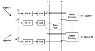
implementation, it may be noted from Fig. 4 that the switched-beam method cannot make full use of the multipath signals, and cannot be used to cancel interferences when located in the main lobe. Thus, the performance of a switched-beam system is less optimal when compared with an adaptive system. This will also be confirmed in Section IV by simulation of several representative cases. Fig. 5 shows a proposed alternative hybrid smart antenna system. The proposed system described in this paper combines the advantages of both switched-beam and
adaptive systems. Unlike traditional
adaptive antenna arrays, the proposed system uses directional elements to achieve additional antenna gain. It does have beam
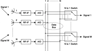
forming capabilities to cancel interferences but uses a smaller number of signals than traditional adaptive systems. Through the proper design of the proposed system, it may be expected that it is possible to achieve a performance similar to that of an adaptive system with the advantage of using a lesser number of signals in the adaptive process. Similar to the traditional switched beam array process, signal selection will be based on combining the strongest signals in the overall array. As shown in Fig. 5, the proposed system inherits part of the characteristics of the switched-beam system, in that it adopts directional antenna elements. It will be described in Section IV that different coverage angles should be chosen in different multipath scenarios to
obtain the best performance. The
arrangement in Fig. 5 also borrows some digital beam forming technology used in adaptive systems, but in this case the beam forming will be done more efficiently using a reduced number of signals. There are additional blocks ( to selector) that select only the ( ) strongest signal streams from total movement of mobile users and the relatively wide beam width of the radiation pattern of antenna elements, the to switches do not need to be updated in real time. It will be shown that in most cases when using the arrangement in Fig. 5, performance similar to that of an eight-element adaptive system can be achieved by using a value of NS as small as 2. It will also be shown that as NS increases, the performance will continue to improve; but the system
complexities will also increase and
Int. J. of Engg. Sci. & Mgmt. (IJESM), Vol. 2, Issue 3: July-Sep.: 2012, 305-314
Fig. 2. Adaptive pattern of one beam-forming block. Desired signals and interferences are denoted by solid arrows
and dashed arrows, respectively
ASSUMPTIONS AND DESCRIPTION OF THE SIMULATION MODEL
Fig. 6 shows a block diagram of an N-element beam forming smart antenna system. The baseband signal received by the antenna array is given by where and are matrices of the channel transfer functions of the multipath signal and interferences respectively and are vectors of the multipath signals and interferences, respectively is the system noise. The channel transfer functions and the signal vectors are given by where operator ( ) indicates the dot product. The element in the multipath channel transfer function represents the propagation transfer function of the multipath signal to the antenna. The matrix element, on the other hand, represents the propagation transfer function of the interference to the antenna. Both and are complex Gaussian random variables. The function describes the antenna amplitude pattern of the antenna element. is the angle of arrival of the multipath of the desired signal and is the angle of arrival of the interference is the multipath of the desired signal is the interference is the noise at the antenna, and is modeled as a stationary, complex, Gaussian process of zero mean and specially white in the processed frequency band. Without loss of generality, all powers were normalized to noise variance. Thus, has
complex Gaussian dis-Fig. 6. Block diagram of an N-element beam forming smart antenna system. tribution; and also have
complex Gaussian distribution .The
expected input signal-to-noise ratio (SNR) for the desired signal and the expected input interference-to-noise ratio (INR) for the th interference are given by Operator denotes complex conjugate and denotes complex conjugate transpose. For omni-directional antenna elements, the received signal at any antenna element will be the sum of identically distributed Gaussian signals. The magnitude of the received signal will thus have a Rayleigh distribution. A Rayleigh
channel corresponds to a multipath
environment where all the arrived signals are multipath signals and where there is no-line-of sight propagation path for the desired signal. When there is a line-of-sight signal, the channel should be modeled as a Rician Channel. The optimum-combining output in this case will be given by For performance simulations of a traditional adaptive array, the distance between adjacent elements is assumed to be a half wavelength and each antenna is assumed to be omni-directional as shown in Fig. 7. As may be seen in Fig. 8, the distance between adjacent elements of a hybrid smart antenna array is also assumed to be a half wavelength; but, in this case, each element is assumed to have its own directional pattern.
Int. J. of Engg. Sci. & Mgmt. (IJESM), Vol. 2, Issue 3: July-Sep.: 2012, 305-314
Fig. 4. Pattern of switched-beam smart antenna. Desired signals and interferences denoted by solid and dashed
arrows, respectively
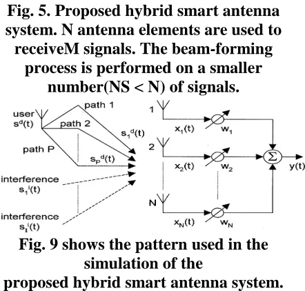
Fig. 5. Proposed hybrid smart antenna system. N antenna elements are used to receiveM signals. The beam-forming
process is performed on a smaller number(NS < N) of signals.
Fig. 9 shows the pattern used in the simulation of the
proposed hybrid smart antenna system.
The pattern has a main beam with a -degree beam width. Neglecting the side lobe power, the power gain of the main beam may be approximately estimated as 360 divided by. The pattern has a 20 dB side lobe and it should be noted that the initial simulation results showed no observable difference in the system performance results when the
side lobe level was varied by as much as10 dB from the utilized 20 dB value. For the case of an eight-element array with equal to 45, the main beam of all the elements will be placed side-by-side to provide the 360 coverage. If is less than 45 there will be gaps that cannot be covered by the collective main beams of the eight-element array, and if is larger than 45 there will be an overlap between the patterns from the various antenna elements. One thing that needs to be mentioned is that in (3) and (4) is the amplitude pattern instead of the power pattern, hence a square root operator is needed to get from the power pattern
normally measured in antenna
characterization. Two kinds of
communication systems, TDMA and
CDMA, were simulated in this paper. For a TDMA system, smart antennas are only used to overcome multipath fading and no co-channel interference is assumed. For a CDMA system, all users share the same frequency and channels are distinguished by different codes. Each user thus interferes with other users who are occupying the same frequency band. In a CDMA system; therefore, a smart antenna is used to overcome both multipath fading and interference. Binary phase shift keying
(BPSK) modulation is used in all
simulations; therefore, the output of an optimum combining in can be simplified to. Also, 500 000 random cases were simulated for each SNR value and for each operating case of the proposed antenna structure.
Fig. 7. Planar (x, y) layout of a traditional adaptive smart antenna array consisting
Int. J. of Engg. Sci. & Mgmt. (IJESM), Vol. 2, Issue 3: July-Sep.: 2012, 305-314
Fig. 8. Planar layout of a hybrid smart antenna array consisting of directional
elements.
Fig. 9. Antenna pattern used for the hybrid smart antenna simulations
Fig. 10. DOA spread versus Smart antenna performance. Simulation assumesno interference, optimum combining, an eight-element array and
five multipath signals RESULTS
Figs. 10–19 show the simulation results for a
TDMA communications system. As
mentioned earlier, this means that the smart antenna array will be concerned only with the multipath effect and no interference consideration will be included.
Three variables are inspected in this paper. The first is the number of elements in the array. As expected, more elements improve
the system performance; but also increase the system complexity. Eight-element arrays are widely used and are considered as a good tradeoff between performance and complexity.
Hence, in all the simulations reported in this paper, we will use eight-element arrays. The second and third variables are all related to the propagation models. One is the DOA spread of a multipath signal and the other is the number of multipath signals. The impact of each of these parameters on the overall system performance was simulated. The following represents samples of the obtained results.
Fig. 10 shows how the performance of an adaptive system is related to the DOA spread of multipath signals. The smart antenna used in this simulation is a traditional optimum-combining adaptive array with eight omni-directional elements. It was assumed that there were five Gaussian multipath signals.
The axis is the SNR at each antenna element and the axis is the bit error rate (BER) of coherent demodulation of BPSK at the array output. It is clear that when the DOA spread of multipath signals decreases from 360 to 10 , the system performance decreases and the SNR required for keeping BER less than 10 has to increase by 7.8 dB, from 4.4 to 12.2 dB. The BER result of a single antenna is also shown as reference by the dotted line in the same figure. This can be explained in terms of the fact that when DOA decreases, multipath signals become more correlated; and hence, cause a decrease in the adaptive array performance.
Int. J. of Engg. Sci. & Mgmt. (IJESM), Vol. 2, Issue 3: July-Sep.: 2012, 305-314 the number of multipath increases from 2 to
12, the system performance increases and the SNR required for keeping BER less than 10 is decreased from 17.1 to 6.9 dB. This improved performance can be explained in terms of the reduced correlation of the signals at each antenna due to the richer multipath environment. For the proposed hybrid smart antenna system, there are five variables that need to be inspected in the simulations. Besides the three variables mentioned above (number of elements, number of multipath, and DOA spread) which are shared with an adaptive smart antenna system, there are two more variables that need to be considered in this case. These include beam width of the directional antenna element and the number of elements that will be chosen for the beam forming process (in Fig. 5). Simulation results show that the first three variables have similar impact on the performance of the proposed hybrid smart antenna design when compared with the adaptive smart antenna system described above. Thus, only the effect of the last two parameters will be presented and discussed here.
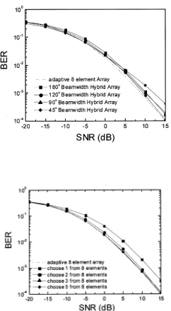
Fig. 12. Performance of a hybrid smart antenna system as a function of the beamwidth of the directional elements. Simulation assumes no interference and that the hybrid array selects and combines two signals from an array of eight elements of directional antennas. 30 DOA spread was assumed. The propagation model used in the simulations in both Figs. 12 and 13 includes five multipath signals with 30 DOA spread. This 30 DOA spread corresponds to a propagation scenario for a base station that is installed on top of a building roof where the use is at a moderate distance from the base station. It is assumed that there are no obstacles around the base station antenna and all multipath signals are caused by cluster reflections around the user. Fig. 12
inspects howa different antenna beam width impacts the performance of the proposed hybrid smart antenna system. A different beam width also means a different gain because the element gain is assumed to be (see Fig. 9 and neglecting the side lobe power). The hybrid smart antenna used in this simulation selects and combines the two largest signals ( ) out of the available ones from the array of eight elements. The dotted line in Fig. 12 shows the results of a traditional adaptive smart antenna method (optimum-combining eight elements) and is included here for reference. From Fig. 12, it is interesting to note that the 120 beam width hybrid array has the best performance, more specifically, that the required SNR to keep BER less than 10 is only 0.67 dB higher than that for a traditional adaptive antenna system.
Int. J. of Engg. Sci. & Mgmt. (IJESM), Vol. 2, Issue 3: July-Sep.: 2012, 305-314 with similar amplitude but different phases.
Thus, a 90 beam width does not provide an optimum multipath combining system. Fig. 15 shows a 120 beam width system
used in the same 30DOA spread
environment. It is clear that, in this case, there is at least two antennas that can simultaneously receive all multipath signals within the assumed 30 DOA spread. Although a 120 beam width system has lower antenna gain, it achieves a higher optimum-combining gain and has a better composite gain than a 90 beam width system. If the element pattern is too wide; however, the element gain will further decrease and the system performance will subsequently decrease. This clarifies the reduction in performance in the 180 beam width case shown in Fig. 12. Considering the fact that a hybrid smart antenna system only requires the number of signals to be as small as two (instead of eight signals) to achieve almost optimum performance, this presents a very encouraging observation and testifies to the significant performance improvement in the proposed hybrid system. Figs. 16 and 17 show simulation results for a propagation model of five multipath signals with 10 DOA spread. It is a similar propagation scenario to that used in the simulation of antennas is not only justifiable but also suggested.
Fig. 13. Performance of a hybrid smart antenna system versus number of elements used by the optimum combining
adaptive process.
Simulation assumes no interference, and the number of signals was changed from one to five in an eight-element array. Simulations were performed for 120 beam width and 30 DOA spread.
Fig. 14. Example of a 90 beam width system used in a 30 DOA spread
Int. J. of Engg. Sci. & Mgmt. (IJESM), Vol. 2, Issue 3: July-Sep.: 2012, 305-314
Fig. 15. Example of a 120 beam width system used in a 30 DOA spread
Environment
Fig. 16. Performance of hybrid smart antennas of directional elements with
different beamwidths
Simulation assumes no interference, and that the hybrid array selects and combines two signals from an eight-element array of directional antennas. 10 DOA spread was also assumed.
Fig.17. Performance of hybrid smart antennas versus number of elements used
by optimum combining.
Interference was included in the simulation, and the hybrid array was assumed to choose one to five signals from eight directional elements. 120 beam width and 30 DOA spread were also assumed. line in Fig. 20 is for the reference adaptive array. It may be also noted that with the proposed presence of interferences in the simulated CDMA system, the performance of the adaptive array was also degraded.
Fig. 21 shows the effect of the number of selected signals NS on the performance of the proposed hybrid smart antenna system. As shown in three signals (instead of two as
in earlier no-interference simulations)
provide excellent combining results and the SNR needed to keep BER less than 10is 0.7 dB higher than that for a traditional adaptive array.
CONCLUSION
Int. J. of Engg. Sci. & Mgmt. (IJESM), Vol. 2, Issue 3: July-Sep.: 2012, 305-314 that the proposed hybrid process is more
efficient as it utilizes a smaller number of signals (two to three instead of eight) in the beam forming process while providing BER values similar to those that can be achieved when using the entire eight signals in the adaptive array. The reduced number of elements also suggests reduced complexity and cost in performing the adaptive signal processing, and even possible improvement in performance as the adaptive process often involves a number of estimations. Specific analysis of the role of estimation on the performance of an adaptive antenna and the impact of a reduced number of estimations on the possible improvement in the accuracy and performance will be discussed in a separate article. Simulation results also showed a less significant impact of the antenna element beam width on the overall performance of the proposed hybrid system. For practical consideration, omni directional elements might as well be used. In this study we used the two or three largest signals from the eight-element array in the optimum-combining process. This may or may not be the best selection depending on the multipath environment. This aspect of the study needs further simulation that will be reported in a future article. Currently, on-going research efforts include taking into
account the characteristics of the
propagation environment, and the possible inclusion of parameters such as polarization diversity in evaluating the performance of the proposed hybrid antenna array system.
Another area of research that is now being pursued is an experimental verification of some of the reported observations by combining the outputs of a set of omni-directional antennas using a Butler matrix. This idea was proposed by one of the reviewers. The most important outcome from the present study; however, is related to the possible use of a smaller number of signals in the optimum-combining adaptive process while maintaining a performance similar to that of a fully adaptive, and, hence, more complex approach.
REFERENCES
[1] S. Bellofiore et al., “Smart antenna
system analysis, integration and
performance for Mobile Ad-Hoc Networks
(MANET’s),” IEEE Trans. Antennas
Propagat., vol. 50, pp. 571–581, May 2002. [2] M. Ho, G. Stuber, and M. Austin, “Performance of switched-beam smart antennas for cellular radio systems,” IEEE Trans. Vehic. Technol., vol. 47, pp. 10–19, Feb. 1998.
[3] R. C. Bernhardt, “The use of multiple-beam directional antennas in wireless
messaging systems,” in Proc. IEEE
Vehicular Technology Conf., 1995, pp. 858– 861.
[4] A. F. Naguib, A. Paulraj, and T. Kailath, “Capacity improvement with BS antenna arrays in cellular CDMA,” IEEE Trans. Vehic. Technol., vol. 43, pp. 691–698, Aug. 1994.e the switched.