VOLUME 3, ISSUE 8, Aug. -2017
SEISMIC RESPONSE OF MULTI-STOREY STRUCTURES WITH FLOATING
COLUMNS
JAMDAR AMEERHUSSAIN SUHELAHMED
P.G. Student of Structural Engineering, Department of Civil Engineering, N.K. Orchid College of Engg & Technology, Solapur, India
PRAKARSH SANGAVE
2Associate Professor, Department of Civil Engineering, N.K. Orchid College of Engg & Technology, Solapur, India
ABSTRACT:
The civil engineering structures with floating column are a regular element in the cutting edge multistory construction. Such elements are profoundly undesirable in building implicit seismically dynamic ranges. This study highlights the significance of expressly perceiving the vicinity of the structures with and without floating columns. Seismic analysis is carried out on G+7 story building with different alternative location for floating column considering the presence and absence of infill effect. Different structural configurations such as Floating column resting on beam which is supported on column, and Providing RCC wall between columns which is supported by frame having floating column are analysed using professional software Etabs-2013. The response of structure is studied in form of Base-Shear, Storey Shear and Storey Displacement, Member forces of Buildings with and without Floating Columns for seismic zone IV subjected to medium soil profile by seismic coefficient method and response spectrum method referring to IS 1893-2002.
KEYWORDS: Floating columns, Infill effect, Base-Shear, Storey Shear and Storey Displacement, Member forces, equivalent static load method, response spectrum method etc.
1.1 INTRODUCTION:
India is a developing country, where urbanisation is at the faster rate in the country including adopting the methods and type of constructing buildings which is under vast development in the past few decades. As a part of urbanisation multi-storey buildings with architectural complexities are constructed and have open first storey as an unavoidable feature. This is primarily being adopted to accommodate parking or reception lobbies in the first storey.
The behavior of a building during earthquakes depends critically on its overall shape, size and geometry, in addition to how the earthquake forces are carried to the ground. Whereas the total seismic base shear as experienced by a building during an earthquake is dependent on its natural period, the seismic force distribution is dependent on the
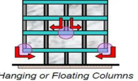
distribution of stiffness and mass along the height and these forces are needed to be brought down along the height to the ground by the shortest path; any deviation or discontinuity in this load transfer path results in poor performance of the building. Buildings with vertical setbacks cause a sudden jump in earthquake forces at the level of discontinuity. Many buildings with an open ground storey intended for parking collapsed or were severely damaged in Gujarat during the 2001 Bhuj earthquake. Buildings with columns that hang or float on beams at an intermediate storey and do not go all the way to the foundation, have discontinuities in the load transfer path.
Fig 1.1: Hotel building having floating column
1.2 FLOATING COLUMN CONCEPT:
VOLUME 3, ISSUE 8, Aug. -2017 Floating columns are competent enough to carry gravity
loading but transfer girder must be of adequate dimensions (Stiffness) with very minimal deflection.
2.1 METHODOLOGY:
To study this structural behavior the software ETABS 2013 program has been to used. ETABS 2013 is an analyzing program that offers general purpose structural analysis and design along with the extensive model generation and post processing facilities. Dynamic analysis shall be performed to obtain design seismic force and its distribution to different levels along the height of the building and lateral loads are assumed to be concentrated at the floor levels for the buildings. The Static and dynamic analysis shall be done by using Static coefficient and response spectrum method resp. according to IS 1893:2002.
2.2 FORMULATION:
In the present study, the multistoried RC moment resisting space framed buildings having Floating Column with and without infill as well as when provided with and without Stay are modeled and analyzed using professional software ETABS 2013 in compliance with the codes IS 456:2000 and IS 1893(Part 1): 2002. Parametric investigation is carried out mainly to study the behavior of Floating Column in presence and absence of infill effect and to check the best possible accommodation of Floating Column with minimum deformations. Parameters such as Base-Shear, Storey Shear, Storey Displacement and Member forces of Buildings when Stay is provided below the floating column is studied and results are obtained so that failures of Floating Column will be avoided and the risk in designer’s mind will vanish. Various cases that are taken for study are given in tabular form representing the investigation work.
2.3 DESCRIPTION OF MODELS WITH DIFFERENT STRUCTURAL SYSTEMS:
2.4 BUILDING DESCRIPTION:
2.5 MODELLING USING ETABS:
CASE I
CASE II
Case No Name of Structural System
I Floating column resting on beam which is supported on column.
II Providing RCC wall between columns which is supported by frame having floating column.
Sr. No Structural Element Dimension
1 Material Used Concrete M-30
Reinforcement Fe-500
2 Number of Storey 7
3 Plan Dimensions 16 X 16 m
4 Type of Structure RCC
5 Typical Storey Height 3.2 m
6 Beam 0.300 X 0.450 m
7 Column 0.300 X 0.300 m
8 Thickness of Slab 0.200 m
9 Thickness of
Masonry Wall 0.150 m
VOLUME 3, ISSUE 8, Aug. -2017 2.6 OBJECTIVE AND SCOPE:
The objective of the present work is to study the Seismic Response of Multi-Storey Structures with Floating Columns. This study is important as Floating Column is unavoidable feature and if not properly analysed or designed will lead to massive failure of structure. Thus G+7 Storey building are studied when Floating Column is provided and when Floating Column is not provided. From this study, we can clearly get an idea of best suitable position for Floating Column. Linear Seismic Analysis is carried out to study the behavior and effect of Floating Column.
3. RESULTS AND DISCUSSIONS:
Linear analysis has been carried out by Seismic Coefficient Method (SCM) and Response Spectrum Method (RSM). After carrying out various investigations on structural configuration like types of building frame i.e. studying floating column behavior firstly when floating column is resting on beam supported on column, secondly by providing shear-wall below Floating Column. Also, complete investigation of frames is carried out by providing Stay and without Stay in presence and absence of infill effect on Floating Column. The results of seismic parameters such as Base-Shear, Storey Shear and Storey Displacement, Member forces of Buildings with and without Floating Columns. For seismic zone IV subjected to medium soil profile. Results are presented in the form of Tables and Graph respectively.
STATIC COEFFICIENT METHOD: CASE -I
Table No. 3.1: Comparison of Vertical Deformation, Bending Moment, Shear Force, Base-Shear.
Type
Without considering infill
effect
With considering infill effect Without
Stay
With stay
Without Stay
With stay
Beam Below the Floatin
g Column
Vertical deformatio n
7.9 5.1 1.5 1.2
Bending
Moment 207.28 103.84 21.56 11.79
Shear force 148.56 95.427 21.84 17.15
Base Shear 660.05 763.71 1695.14 1688.0 7
Graph No 1: Comparison of Vertical Displacement.
1. There is sudden drop is observed in vertical deformation by providing the stay below the floating column.
2. The vertical deformation is reducing by 36% and 20% in case of with and without infill effects.
Graph No 2: Comparison of Bending Moments when Floating Column is resting on Beam which is Supported by
Column.
1. Fall of 50% in value of bending moment is observed after comparing frame with and without stay in case of frame without infill effect.
2. Similarly, after comparing frame with and without infill effect for with and without stay case drop of approximately 88% in value of bending moment is commonly observed.
Graph No 3: Comparison of Shear Force when Floating Column is resting on Beam which is Supported by Column.
1. Similar pattern of drop is observed in Shear force value of around 83% of frame with and without infill effect in case of with and without stay after observing drop pattern of Bending moment.
Graph No 4: Comparison of Base-Shear when Floating Column is resting on Beam which is Supported by Column.
1. There is increase in value of base shear after providing infill effect in the both with and without stay cases.
2. The base shear value is increased by 61% and 55% in case of without stay and with stay by considering infill effect.
VOLUME 3, ISSUE 8, Aug. -2017
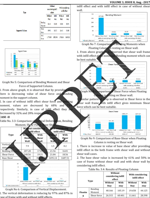
Graph No 5: Comparison of Bending Moment and Shear Force of Supported Column.
1. From above graph, it is observed that by providing stay there is decreasing value of shear force and bending moment in the support column.
2. In case of without infill effect shear force and bending moment, values are decreased by 68% and 73% respectively. Similarly, in case of infill effect they are decreased by 32% and 28% respectively.
CASE -II
Table No. 3.3: Comparison of Vertical Deformation, Bending Moment, Shear Force, Base-Shear.
Type
Without considering infill effect
With considering infill effect Without
Shear Wall
With Shear
Wall
Without Shear
Wall
With Shear Wall
Vertical
deformation 7.9 0.2 1.5 0.2
Bending Moment 207.28 17.83 21.56 16.81
Shear Force 148.56 19.21 21.84 18.56
Base Shear 660.05 835.78 1695.14 1687.51
Graph No 6: Comparison of Vertical Displacement. 1. The vertical deformation is reducing by 97% and 87% in case of frame with and without infill effects.
2. Sudden drop of 81% in vertical deformation is observed from above graph after comparing space frame without
infill effect and with infill effect in case of without shear wall.
Graph No 7: Comparison of Bending Moments when Floating Column is resting on Shear wall.
1. From above graph, it is observed that shear wall frame with infill effect gives minimum Bending moment which can be best suitable.
Graph No 8: Comparison of Shear Force when Floating Column is resting on Shear wall.
1. Similar pattern of drop is observed in Shear force in the shear wall frame with infill effect gives minimum Shear force which can be best suitable.
Graph No 9: Comparison of Base-Shear when Floating Column is resting on Shear wall.
1. There is increase in value of base shear after providing infill effect in the both frame with shear wall and without shear wall cases.
2. The base shear value is increased by 61% and 50% in case of frame without shear wall and with shear wall by considering infill effect.
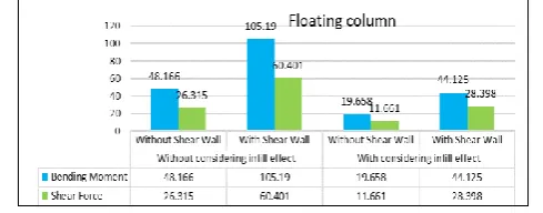
Table No. 3.4: Results of Floating Column
Type
Without considering infill
effect
With considering infill effect Without
Stay
With stay
Without Stay
With stay
Floatin g Column
Bending
Moment 48.166 105.19 19.658 44.125
Shear force 26.315 60.401 11.661 28.398
Axial Force 106.427 1204.0
8 480.122
VOLUME 3, ISSUE 8, Aug. -2017
Graph No 10: Comparison of Bending Moment and Shear Force on Floating Column.
1. There is increase in value of shear force and bending moment by providing shear wall below the floating column. 2. In case of without infill effect shear force and bending moment, values are increased by 56% and 54% respectively. Similarly, in case of infill effect they are increased by 60% and 58% respectively.
Graph No 11: Comparison of Axial force of Floating column. 1. By providing shear wall there is drastically rise in value of axial forces in both infill effect and without infill effect frame.
2. Rise in value of 91% of axial forces is observed in case of without infill effect frame after providing shear wall. 3. Similarly, in case of frame with infill effect axial force value increased by 47%.
RESPONSE SPECTRUM METHOD: CASE -I
Table No. 3.5: Comparison of Vertical Deformation, Bending Moment, Shear Force, Base-Shear.
Type
Without considering infill
effect
With considering infill effect Without
Stay
With stay
Without Stay
With stay
Beam Below the Floatin
g Column
Vertical deformatio n
7.9 5.1 1.5 1.2
Bending
Moment 207.28 103.84 17.80 11.54
Shear force 148.56 95.42 19.73 17.10
Base Shear 553.54 606.87 1576.94 1562.6 0
Graph No 12: Comparison of Vertical Displacement.
1. Sudden drop of 81% in vertical deformation is observed from above graph after comparing space frame without infill effect and with infill effect in case of without stay. 2. Similarly, in case of with stay drop of 76% in vertical deformation is observed from above graph after comparing space frame without infill effect and with infill effect.
Graph No 13: Comparison of Bending Moments when Floating Column is resting on Beam which is Supported by
Column.
1. Fall of 50% in value of bending moment is observed after comparing frame with and without stay in case of frame without infill effect.
2. Similarly, after comparing frame with and without infill effect for with and without stay case drop of approximately 90% in value of bending moment is commonly observed.
Graph No 14: Comparison of Shear Force when Floating Column is resting on Beam which is Supported by Column.
1. Similar pattern of drop is observed in Shear force value of around 85% of frame with and without infill effect in case of with and without stay after observing drop pattern of Bending moment.
Graph No 15: Comparison of Base-Shear when Floating Column is resting on Beam which is Supported by Column.
1. There is increase in value of base shear after providing infill effect in the both with and without stay cases.
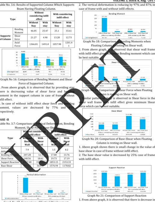
VOLUME 3, ISSUE 8, Aug. -2017 Table No. 3.6: Results of Supported Column Which Supports
Beam Having Floating Column.
Type
Without considering infill
effect
With considering infill effect Without
Stay
With stay
Without Stay
With stay
Supporte d Column
Bending
Moment 46.05 25.47 25.1 33.61
Shear
force 21.27 4.90 13.28 12.73
Axial
Force 1366.81 1491.0 1057.98
1261.4 1
Graph No 16: Comparison of Bending Moment and Shear Force of Supported Column.
1. From above graph, it is observed that by providing stay there is decreasing value of shear force and bending moment in the support column in case of frame without infill effect.
2. In case of without infill effect shear force and bending moment, values are decreased by 77% and 45% respectively.
CASE -II
Table No. 3.7: Comparison of Vertical Deformation, Bending Moment, Shear Force, Base-Shear.
Type
Without considering infill effect
With considering infill effect Without
Shear Wall
With Shear
Wall
Without Shear
Wall
With Shear Wall
Vertical
deformation 7.9 0.2 1.5 0.2
Bending Moment 207.28 12.1 17.80 13.76
Shear Force 148.56 18.61 19.73 17.19
Support Reaction 2157.00 1589.43 1853.15 2153.33
Base Shear 553.54 561.17 1576.94 1178.82
Graph No 17: Comparison of Vertical Displacement.
1. There is sudden drop is observed in vertical deformation by providing the shear wall below the floating column.
2. The vertical deformation is reducing by 97% and 87% in case of frame with and without infill effects.
Graph No 18: Comparison of Bending Moments when Floating Column is resting on Shear wall.
1. From above graph, it is observed that shear wall frame with infill effect gives minimum Bending moment which can be best suitable.
Graph No 19: Comparison of Shear Force when Floating Column is resting on Shear wall.
1. Similar pattern of drop is observed in Shear force in the shear wall frame with infill effect gives minimum Shear force which can be best suitable.
Graph No 20: Comparison of Base-Shear when Floating Column is resting on Shear wall.
1. Above graph shows there is small change in the value of base shear in case of frame without infill effect.
2. The base shear value is decreased by 25% case of frame with infill effect.
Graph No 21: Comparison of Support Reaction 1. From above graph, it is observed that there is decrease in value of support reaction by providing shear wall in case of without infill effect.
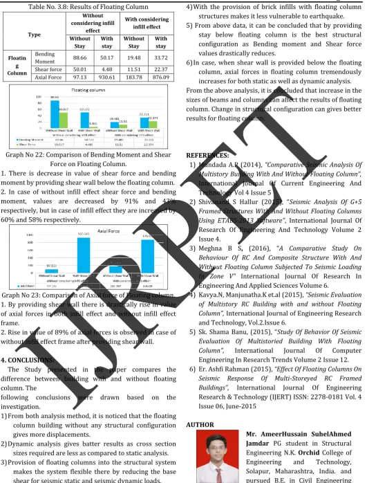
VOLUME 3, ISSUE 8, Aug. -2017 Table No. 3.8: Results of Floating Column
Type
Without considering infill
effect
With considering infill effect Without
Stay
With stay
Without Stay
With stay Floatin
g Column
Bending
Moment 88.66 50.17 19.48 33.72
Shear force 50.01 4.48 11.51 22.37
Axial Force 97.13 930.61 183.78 876.09
Graph No 22: Comparison of Bending Moment and Shear Force on Floating Column.
1. There is decrease in value of shear force and bending moment by providing shear wall below the floating column. 2. In case of without infill effect shear force and bending moment, values are decreased by 91% and 43% respectively, but in case of infill effect they are increased by 60% and 58% respectively.
Graph No 23: Comparison of Axial force of Floating column. 1. By providing shear wall there is drastically rise in value of axial forces in both infill effect and without infill effect frame.
2. Rise in value of 89% of axial forces is observed in case of without infill effect frame after providing shear wall.
4. CONCLUSIONS:
The Study presented in the paper compares the difference between building with and without floating column. The
following conclusions were drawn based on the investigation.
1) From both analysis method, it is noticed that the floating column building without any structural configuration gives more displacements.
2) Dynamic analysis gives batter results as cross section sizes required are less as compared to static analysis. 3) Provision of floating columns into the structural system
makes the system flexible there by reducing the base shear for seismic static and seismic dynamic loads.
4) With the provision of brick infills with floating column structures makes it less vulnerable to earthquake. 5) From above data, it can be concluded that by providing
stay below floating column is the best structural configuration as Bending moment and Shear force values drastically reduces.
6) In case, when shear wall is provided below the floating column, axial forces in floating column tremendously increases for both static as well as dynamic analysis. From the above analysis, it is concluded that increase in the sizes of beams and columns can affect the results of floating column. Change in structural configuration can gives better results for floating column.
REFERENCES:
1) Mundada A.P (2014), “Comparative Seismic Analysis Of Multistory Building With And Without Floating Column”, International Journal Of Current Engineering And Technology Vol 4 Issue 5
2) Shivanand S Hallur (2015), “Seismic Analysis Of G+5 Framed Structures With And Without Floating Columns Using ETABS-2013 Software”, International Journal Of Research Of Engineering And Technology Volume 2 Issue 4.
3) Meghna B S, (2016), “A Comparative Study On Behaviour Of RC And Composite Structure With And Without Floating Column Subjected To Seismic Loading In Zone V” International Journal Of Research In Engineering And Applied Sciences Volume 6.
4) Kavya.N, Manjunatha.K et.al (2015), “Seismic Evaluation of Multistory RC Building with and without Floating Column”, International Journal of Engineering Research and Technology, Vol.2.Issue 6.
5) Sk. Shama Banu, (2015), “Study Of Behavior Of Seismic Evaluation Of Multistoried Building With Floating Column”, International Journal Of Computer Engineering In Research Trends Volume 2 Issue 12. 6) Er. Ashfi Rahman (2015), “Effect Of Floating Columns On
Seismic Response Of Multi-Storeyed RC Framed Buildings”, International Journal Of Engineering Research & Technology (IJERT) ISSN: 2278-0181 Vol. 4 Issue 06, June-2015
AUTHOR
VOLUME 3, ISSUE 8, Aug. -2017 Engineering and Technology,