Simulation of Current-Voltage (I-V) and Power-Voltage (P-V)
Characteristics of PV Module using Single-Diode Model in
Irradiance and Temperature Effects
Mya Ei Mon¹, Nay Win Zaw²Abstract--- This paper simulates the mathematical model of the PV (photovoltaic) module based on the MATLAB script file with all the parameters are involved. Modeling this device environmental factors such as irradiation and temperature are used as input variables. The output of the PV module varies depending on the environmental factors. Any changes in the inputs immediately implies changes in outputs. Physical parameters (series and shunt resistance, ideality factor, temperature coefficient of current and voltage, etc.) are significant effects on the operating curves of solar PV module. The aim of this modeling is to study the nature of nonlinear outputs of PV panel and to extract the physical unknown parameters for a given module. The chosen model is the single-diode model with both series and shunt resistances for precise output and investigates all parameters influence on solar PV module operation and focus on a program developed in MATLAB/M-file of 50W PV module. In the result of simulation the voltage, current, and power of PV panel decreased when the solar irradiance decreased and also they are increased when the temperature decreased. When compared the two results of the program simulation results and manufacturer’ data sheets are found the two are identical at STC condition.
Index Terms--- Solar energy, PV module, I-V and P-V characteristics, Irradiance, Temperature
I. INTRODUCTION
Valuable energy can extract from our
surroundings by several ways. These include energy extraction from sunlight, wind, biomass, sea levels, etc. All these ways are renewable in nature. The energy source itself renews, which can provide energy forever. Among all renewable energy strategies, photovoltaic system has own several fundamental advantages compare to others. By using semiconductor devices, solar
energy has identified as a static, movement-free and quiet alternative energy which can result to a long-term and low maintenance cost renewable system.
Solar cells can convert sun light into electricity directly. That produces DC voltage and DC electricity. A PV module is comprised many solar cells that are connected in series or parallel depends on the desired amount of voltage or current. A typical PV cell can produces 0.5V (2-3W). The PV module is the fundamental conversion unit of a PV generator system. So, it is necessary to model the PV module for the design and simulation of maximum power point tracking (MPPT) for PV system applications since PV module has non-linear characteristics. For a given environmental conditions, there is Maximum Power Point (MPP), an optimal point on the V-I curve, where maximum power output is achieved. So, at the MPP the efficiency will be optimized. The performance of the PV module is specified under Standard Test Condition (STC), where the irradiance is 1000W/m2, module temperature is 25°C and air mass is 1.5. This paper presents the modeling method and simulation of photovoltaic (PV) module. The parameters for the PV module are based on the manufacturers‟ data sheets values.
II. MATHEMATICAL MODELING OF A ….PV MODULE
A solar cell is a basic unit of a solar module. A PV module is comprised many solar cells in series and parallel. For consider only a single solar cell, it can be modeled by utilizing a current source, a diode and two resistors. This model represents a single diode model of a solar cell.
Iph V
Id
Iph I I R R V Id p p s
Fig.2. Single-diode model of a solar cell A diode is connected in anti-parallel with the photocurrent in Figure 2 and the output current is obtained by Kirchhoff‟s law;
IIphIdIp (1) Where, Iphis the photocurrent, Ip is the current in the shunt resistor, and Idis the diode saturation current and is given by the equation;
s d o t V [ ( ) ] A I .N .V I exp 1 (2)
Where, V is the voltage imposed on the diode.
o
I is the saturation current of the diode, Vt is the
thermal voltage of its exclusive dependence of temperature. Ns is the number of PV cells
connected in series. A is the ideal factor of the diode and it depends on the PV cell technology. [2]
Vt k.Tc q
(3) Where, Tcis the actual cell temperature (K), k is Boltzmann‟s constant (1.3805x10⁻²³
J/K) and q is Electron charge (1.6021x10⁻¹⁹ C).So, the output current is s s ph o s t p V I.R V I.R I I I [exp( ) 1] A.N .V R (4)
The power produced by a single PV cell is less and not enough for almost any applications. So, the cells may be configured in series and parallel features to increase the capability of overall PV systems. Equation (4) can be expressed as;
p s s s p ph p o s t p s N V I.R .N V I.R I N I N I [exp( ) 1] A.N .V R .N (5)
Where,Npas the number of cells connected in
parallel, Rs and Rpare the series and shunt resistance of the solar cell.
III. FINDING THE PARAMETERS Modeling the PV devices, if the number of unknown parameters increases the results are away from being the ideal form. Most of the manufacturer‟s datasheets do not provide enough
information about the parameters which depends on weather conditions. There are five parameters (Iph,Io, A, Rs, Rp) are considered depends on the irradiation and cell temperature. Ideality factor (A) is chosen 1.3 for silicon. [2]
1) Finding Iph
To simply the model, the effect of shunt resistance is not considered since usually the shunt resistance Rp is large and the series resistance Rs
is small. So, ignore the last term in (4) and the output current at STC conditions output current at the STC condition is;
ph o s t V I = I I [exp( ) 1] A.N .V (6)
When the PV cell is short-circuited;
sc ph on s t 0 ' ' I [exp( ) 1] I I A.N .V (7) In ideal case, sc ph ' ' I I (8)
Where, Isc' is short circuit current and Iph' is
photocurrent and Ionis the reverse saturation
current at STC conditions. Photocurrent or light generated current mainly depends on the solar radiation and cell working temperature, So
sc ph i c n n G ' I (I K (T T )) G (9)
Where, G:Irradiance(W/m²),Gn:Irradiance at STC(1000W/m²), Tc: cell temperature (K),Tn:
Cell temperature at STC (25+273=298K).Ki is coefficient temperature of current (A/K).
2) Finding
I
oThe solar cell has three points at STC conditions: (i) Voltage at open circuit condition
(I = 0, V=Voc' )
(ii) Current at short circuit condition (V = 0, I =Isc' )
(iii) Maximum Power Point condition (Vmp,Imp) So, the following equation can be written as, s ph o s t V I.R I I I [exp( ) 1] A.N .V ………..(10)
ph on oc s t ' V ' 0 I I [exp( ) 1] A.N .V (11)
For short circuit condition;
sc ph on sc s s t ' .R I ' ' I [exp( ) 1] I I A.N .V (12)
For maximum power point condition;
…… mp mp s ph mp on s t V I .R ' I I I [exp( ) 1] A.N .V (13)
Where, Voc' is open circuit voltage at STC
condition. Since (-1) is too smaller than the exponential term it is neglect. SinceIsc' Iph' ,
Equation (11) will be „‟‟‟‟‟‟ 1111 sc on oc s t ' V ' 0 I I [exp( )] A.N .V (14) on sc oc s t ' V ' I I [exp( )] A.N .V (15) The diode saturation current is directly influenced
by environmental changes and it can be determined by the following mathematical equation; o on c 3 g n n c q.E T 1 1 I I ( ) exp( ( )) T A.k T T (16)
Where,Egis the band gap energy for the silicon semiconductor which is between 1.1 and 1.12 eV.
3) Finding
R
s and RpSometimes manufacturer‟ data sheets do not provided these values. But they are strongly affect the characteristics of solar modules. In this paperRsand Rpvalues are extracted by setting the
computed maximum power (Pmp) is equal to the
experimental one (Pmp,ex) at STC conditions.
Iterative solution method is also used to determine the Rs and Rpresistance values. There is only one
point corresponding to a single value of Rsthat satisfies the imposed condition Pmpat the
maximum point. And then the Rpvalue is
calculated as the following equation; mp mp mp P I V (17) mp mp s mp mp s ph mp on s t p V I .R V I .R ' I I I [exp( ) 1] A.N .V R (18) Substituting I'phand Ionin (18); mp mp s p mp oc mp s oc sc sc sc s t s t V I .R R ' ' V I .R V V ' ' [exp( )] ' [exp( )] I I I A.N .V A.N .V (19)
In determining Rs and Rp, the values are initially unknown and so initial guesses for Rs and Rp are necessary before the iterative process starts. The initial value of Rs assume zero. The initial value of Rpmay be given by p p,min mp oc mp mp sc mp ' V V V R R ' I I I -= = (20) Although Rpis still unknown, it surely greater than Rp,minand this is a good initial guess. [11]
According to the iterative process Rs must be slowly incremented starting from Rs= 0 and then
p
R is calculated from the Equation (19) and requires several iterations until Pmp=Pmp,ex.
Iterative processes stop at the computed maximum power (Pmp) matches with the experimental result
(Pmp,ex). In this way Rs and Rpvalues are
extracted.
IV. NONLINEAR CHARACRERISTICS OF PV MODULE
The output of the PV module is unstable when weather conditions changes. So the proper nonlinear methods should be used for this unstable conditions. In this proposed model Newton-Raphson method is chosen.
n 1 n n ' n) f (X ) X X f (X (21)
In which f (X )n is the actual amount of the function, f (X' n)is the derivation of the function,
n
X is the current amount and Xn 1 is the next
amount. Newton-Raphson method needs one iteration loop which continues its operation, until the stopping point condition is met.
n 1 n n 1 I I Error x100 I (22)
The two different ways for stopping condition is: (1) Once the pre-specified numbers of iteration is done.
(2) Once the present error which can be obtained by using (22) is less than the pre-specified error.[5]
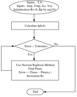
Inputs : T,G Inputs : Imp, Vmp, Isc, Voc Initialisation Rs=0, Rp by eq(19)
Calculate Iph,Io
Error > Tolerance
Use Newton Raphson Method Find Pmax Error = | Pmax – Pmax,e |
Increment Rs
End
No Yes
Fig.3. Iteration flowchart
Table I. Electrical Characteristics of RL-6P050/18 PV Module (50W)
Parameters Values
Maximum Power (Pmax) 50W
Power Tolerance ±3%
Maximum Power Voltage (Vmp)
17.9V Maximum Power Current (Imp) 2.79A Open Circuit Voltage (Voc) 22.1V Short Circuit Current (Isc) 2.97A Maximum System Voltage 1000VDC Operating Temperature -40˚C to + 85˚C Product Application Class A
Weight 4.5KG
Dimension 760x510x30mm
All technical data at standard test conditions: AM = 1.5,
G=1000W/m², T=25˚C.
V. MATLAB SCRIPT FILE FOR PV MODULE %%Information from the RL-6P050/18 solar module datasheet %%
clear; clc;
Vocn = 22.1; %Nominal open-circuit voltage (V) Iscn = 2.97; %Nominal short-circuit current (A) Vmp = 17.9; %Maximum voltage (V)
Imp = 2.79; %Maximum current (A) Eg = 1.12; % Band gap energy (eV) Np = 1; % Number of parallel cells Ns = 36; % Number of series cells
Pmax_e = Vmp*Imp; %Module maximum output power (W)
Ki = 0.0013; % Temperature coefficient of current (A/K)
Kv = -0.0079;%Temperature coefficient of voltage (V/K)
Gn = 1000; % Nominal irradiance (W/m²) Tn = 298; %Nominal operating temperature (K) Tc = Ta+273; % Cell temperature (K)
%% Constants %%
k = 1.3805*10^(-23); % Boltzmann constant (J/K) q = 1.6021*10^(-19); % Electron charge (C) A = 1.3; % Diode ideality factor
Vtn = (k*Tn)/q; % Thermal junction voltage (nominal)
Vt = (k*T)/q; %Thermal junction voltage (current temperature)
G = input ('G:'); % Actual irradiance (W/m²) Ta = input ('Ta:'); % Actual temperature (K) %% Reference values of Rs and Rp %% Rs_max = (Vocn-Vmp)/Imp;
Rp_min = Vmp/(Iscn-Imp)-Rs_max; Rs = 0; %Initial value of Rs
Iph = (Iscn+Ki*(T-Tn))*G/Gn; %Nominal
photocurrent (A)
Ion = Iscn/ (exp (Vocn/(A*Ns*Vt))-1); %Nominal diode saturation current (A)
Io=Ion*(Tc/Tn)^(3)*exp((q*Eg)/(k*A)*(1/Tn-1/Tc)); % Diode reverse saturation current (A)
error = Inf; %dummy value
%% Iterative process for Rs and Rp until Pmax = Pmax,ex %% while (error>0.001) Rs = Rs+0.01; %Increment Rs Rp=(Vmp+(Imp*Rs))/(Iscn(Iscn*exp((Vmp+(Imp *Rs)-(Vocn)/(A*Ns*Vt)))+(Iscn*exp(Vocn/(A*Ns*Vt)) )-(Pmax_e/Vmp); % Shunt resistance V = 0:0.1:50; % Voltage vector I = zeros (1, size(V,2)); % Current vector %% Solve with Newton-Raphson method %% for j = 1:size(V,2)
g(j)=Np*Iph-I(j)- Np*Io*exp((V(j)+(I(j)*Rs))/(A*Ns*Vt)-1)-((Np/Ns*V(j))+(I(j)*Rs))/Rp; while (abs(g(j))>0.001) g(j)=Np*Iph-I(j)-Np*Io*exp((V(j)+(I(j)*Rs))/(A*Ns*Vt)-1) - ((Np/Ns*V(j))+(I(j)*Rs))/Rp; f(j) = -1-(Np*Io*Rs)/(A*Ns*Vt)* exp((V(j)+(I(j)*Rs))/(A*Ns*Vt)); I_(j) = I(j) - g(j)/f(j); I(j) = I_(j); end end P = (Np*Iph-Io*(exp((V+I.*Rs)/(A*Ns*Vt))-1)-(V+I.*Rs)/Rp).*V; % Calculate power
Pmax_m = max(P); error = Pmax_m-Pmax_e; end
VI. SIMULATION RESULTS OF PV MODULE
Fig.4. I-V curve with varying temperature and constant irradiance (G=1000W/m²)
Fig.5. P-V curve with varying temperature and constant irradiance (G=1000W/m²)
Fig.4 and Fig.5 show the temperature increase around the solar cell has a negative impact on the power generation capability. When increasing the temperature (25˚C to 100˚C) (I-V) and (P-V) curves of PV module shifts towards the left and voltage drop drastically although the current is staying constant. This leads to net reduction in power output with increase in temperature. So, the maximum power also decreases with increase in temperature.
Fig.6. I-V curve with varying irradiance and constant temperature (T=25˚C)
Fig.7. P-V curve with varying irradiance and constant temperature (T=25˚C)
The effect of irradiance on the current-voltage (I-V) and power-voltage (P-(I-V) characteristics can be seen in Fig.6 and Fig.7. When varying the irradiance (200W/m² to 1000W/m²) the current of the PV module increases sharply and the voltage also increase slightly. So, the photo generated current is directly proportional to the irradiance. As the effect on both the current and voltage is
positive and the effect on the power is also positive. Therefore, the more irradiation on the solar cell, the more power is generated.
VII. CONCLUSION
The presented paper is the simulation of PV cell and module implemented under MATLAB/M-file. In this paper seen that the PV module output parameters can be varied depending on their cell temperature and irradiation. Also the simulation results are matched with the manufacturer‟ data sheets. It is importance to computeRsand
p
R because the experimental maximum output power does not match with the computed one in most case. So the iteration process and appropriate iteration method should be used for matching. Rs
is iteratively increased until the match condition. In the proposed model show the result (Pmax= 49.933Ω) is great accuracy with the datasheet (Pmp,ex=VmpxImp= 49.941Ω). Therefore, this
model can be used to study all types of commercial PV modules and determine all necessary parameters under new conditions of irradiance and temperature and then, obtain the I-V and P-I-V characteristics.
ACKNOWLEDGMENT
The author would like to thanks my supervisor Dr. Nay Win Zaw, Head of the Department of Electronic Engineering, and all of teachers from West Yangon Technological University who gave advices, fully guidance and supports to complete this paper.
REFERENCES
[1] H. Patel and V. Agarwal, “Matlab-Based Modelling to Study the Effects of Partial Shading on PV Array Characteristics,” IEEE Transactions on Energy Conversion,Vol. 23, pp. 302-310, 2008.
[2] Huan-Liang Tsai., Ci-Siang Tu., Yi-Jie Su., “Development of generalized photovoltaic
model using MATLAB/Simulink”,
Proceedings of the World Congress on
Engineering and Computer Science October 22 - 24,2008. San Francisco, USA.
[3] Bhatt, H.G and Thakker, R.A, “Matlab Based Simulation of Photovoltaic Solar Cell and its Array at Different Temperature Values”,
National Conference on Recent Trends in
Engineering & Technology, B.V.M.
Engineering College, Gujarat, pp.1 -4, 2011. [4] Kumari, S. and Babu, S., “Mathematical
Modelling and Simulation of Photovoltaic Cell using MATLAB/Simulink Environment”, International Journal of Electrical and Computer Engineering (IJECE) Vol. 2, No.1, pp. 26-34, 2012.
[5] M.S.Mahmodian, R.Rahmani, E.Taslimi, S.Mekhilef, “Step and Step Analyzing, Modeling and Simulation of Single and Double Array PV System in Different Enviromental Variability,” International Conference on Future Environment and Energy IPCBEE Vol.28, 2012.
[6] M. Edouard and D. Njomo, “Mathematical Modeling and Digital Simulation of PV Solar Panel using MATLAB Software,” Vol. 3, no. 9, pp. 24–32, 2013.
[7] Fezzani, A., Mahammed, I.H., Said, S., “MATLAB-based modeling of shading effects in photovoltaic arrays,” 15th International Conference on Sciences and Techniques of
Automatic Control and Computer
Engineering-STA2014, Hammamet, Tunisia, pp. 781–787
[8] Ami Shukla, Manju Khare, and K N Shukla, “Modeling and Simulation of Solar PV
Module on MATLAB/Simulink”,
International Journal of Innovative Research in Science, Engineering and Technology, Vol.4,Issue 1, January 2015.
[9] Arjyadhara Pradhan, Dr. S.M.Ali, “Analysis of solar PV performance with change in temperature”, International Journal of Applied Engineering Research Volume 11,Issue 7, 1 May 2016.
[10]Arjyadhara Pradhan and Bhagbat Panda., “Performance Analysis of Photovoltaic
Module at changing Environmental
condition using Matlab Simulink”,
International Journal of Applied Engineering Research ISSN 0973-4562 Volume 12, Number 13 (2017) pp. 3677-3683.
[11]Amar Necaibia, Nadir Boutasseta, Samir Mouhajer.,”A Simple Theoretical Method for
the Estimation of Dynamic Resistance in Photovoltaic Panels”, International Journal of Computer Applications (0975-8887) Volume 45-No.14, May 2012.
Mya Ei Mon received Bachelor of Engineering degree in Electronic Engineering from Hinthada Technological University in 2010. She is currently working toward the Master of Engineering in West Yangon Technological University.
Nay Win Zaw received Master of Engineering and PhD degree in Electronic Engineering from Mandalay Technological University. He worked as Professor in the Department of Electronic Engineering and worked as the Head of Department.