LI4278
PRODUCT REFERENCE
GUIDE
LI4278
PRODUCT REFERENCE GUIDE
72E-151834-01
Revision A
January 2012
No part of this publication may be reproduced or used in any form, or by any electrical or mechanical means, without permission in writing from Motorola. This includes electronic or mechanical means, such as
photocopying, recording, or information storage and retrieval systems. The material in this manual is subject to change without notice.
The software is provided strictly on an “as is” basis. All software, including firmware, furnished to the user is on a licensed basis. Motorola grants to the user a non-transferable and non-exclusive license to use each software or firmware program delivered hereunder (licensed program). Except as noted below, such license may not be assigned, sublicensed, or otherwise transferred by the user without prior written consent of Motorola. No right to copy a licensed program in whole or in part is granted, except as permitted under copyright law. The user shall not modify, merge, or incorporate any form or portion of a licensed program with other program material, create a derivative work from a licensed program, or use a licensed program in a network without written permission from Motorola. The user agrees to maintain Motorola’s copyright notice on the licensed programs delivered hereunder, and to include the same on any authorized copies it makes, in whole or in part. The user agrees not to decompile, disassemble, decode, or reverse engineer any licensed program delivered to the user or any portion thereof.
Motorola reserves the right to make changes to any software or product to improve reliability, function, or design.
Motorola does not assume any product liability arising out of, or in connection with, the application or use of any product, circuit, or application described herein.
No license is granted, either expressly or by implication, estoppel, or otherwise under any Motorola, Inc., intellectual property rights. An implied license only exists for equipment, circuits, and subsystems contained in Motorola products.
Warranty
For the complete Motorola hardware product warranty statement, go to: http://www.motorola.com/enterprisemobility/warranty.
iii
Revision History
Changes to the original guide are listed below:
Change Date Description
Warranty ... ii
Revision History ... iii
About This Guide
Introduction ... xv
Scanner Configurations ... xv
Related Product Line Configurations ... xvii
Chapter Descriptions ... xxi
Notational Conventions... xxii
Related Documents ... xxiii
Service Information ... xxiii
Chapter 1: GETTING STARTED
Introduction ... 1-1
Interfaces ... 1-2
Unpacking the Linear Imager Scanner and Cradle ... 1-2
Parts ... 1-3
Scanner ... 1-3
CR0078-S/CR0008-S Series Cradle ... 1-4
CR0078-P Series Cradle ... 1-6
Linear Imager Scanner Cradle ... 1-7
Connecting the CR0078-S/CR0008-S Series Cradle ... 1-8
Supplying Power to the CR0078-S/CR0008-S Cradle ... 1-8
Connecting the CR0078-P Series Cradle ... 1-9
Supplying Power to the CR0078-P Cradle ... 1-9
Lost Connection to Host ... 1-10
Mounting the Cradle ... 1-10
Replacing the Linear Imager Scanner Battery ... 1-11
Charging the Linear Imager Scanner Battery ... 1-12
Turning Off the Linear Imager Scanner Battery ... 1-12
Reconditioning the Linear Imager Scanner Battery ... 1-13
Battery Reconditioning LED Definitions ... 1-13
Inserting the Linear Imager Scanner in the Cradle ... 1-14
Inserting Linear Imager Scanner in the CR0078-S/CR0008-S Cradle ... 1-14
Horizontal Cradle Mount ... 1-14
Vertical Cradle Mount ... 1-14
Inserting/Removing Linear Imager Scanner in the CR0078-P Cradle ... 1-15
Wall Mount Bracket Template ... 1-17
Radio Communications ... 1-18
Configuring the Linear Imager Scanner ... 1-18
Accessories ... 1-18
Lanyard ... 1-18
Chapter 2: SCANNING
Introduction ... 2-1
Beeper and LED Definitions ... 2-1
Cradle LED Definitions ... 2-5
Scanning ... 2-6
Aiming ... 2-6
Hand-Held Scanning ... 2-6
Hands-Free Scanning ... 2-7
Decode Ranges ... 2-8
Chapter 3: MAINTENANCE, TROUBLESHOOTING & TECHNICAL SPECIFICATIONS
Introduction ... 3-1
Maintenance ... 3-1
Known Harmful Ingredients ... 3-1
Approved Cleaning Agents ... 3-1
Cleaning the Linear Imager Scanner ... 3-2
Cleaning the Linear Imager Scanner Cradles ... 3-2
Battery Information ... 3-3
Troubleshooting ... 3-4
Technical Specifications ... 3-9
Cradle Signal Descriptions ... 3-13
Chapter 4: RADIO COMMUNICATIONS
Introduction ... 4-1
Scanning Sequence Examples ... 4-1
Errors While Scanning ... 4-1
Radio Communications Parameter Defaults ... 4-2
Wireless Beeper Definitions ... 4-3
Radio Communications Host Types ... 4-3
Bluetooth Technology Profile Support ... 4-5
Master/Slave Set Up ... 4-5
Master ... 4-5
Slave ... 4-5
Bluetooth Friendly Name ... 4-6
Discoverable Mode ... 4-6
HID Host Parameters ... 4-7
HID Country Keyboard Types (Country Codes) ... 4-7
Table of Contents
vii
HID Keyboard Keystroke Delay ... 4-9
HID CAPS Lock Override ... 4-9
HID Ignore Unknown Characters ... 4-10
Emulate Keypad ... 4-10
HID Keyboard FN1 Substitution ... 4-11
HID Function Key Mapping ... 4-11
Simulated Caps Lock ... 4-12
Convert Case ... 4-12
Auto-reconnect Feature ... 4-13
Reconnect Attempt Beep Feedback ... 4-14
Reconnect Attempt Interval ... 4-15
Auto-reconnect in Bluetooth Keyboard Emulation (HID Slave) Mode ... 4-16
Out of Range Indicator ... 4-17
Beep on Insertion ... 4-17
Linear Imager Scanner(s) To Cradle Support ... 4-18
Modes of Operation ... 4-18
Point-to-Point Communication ... 4-18
Multipoint-to-Point Communication ... 4-18
Parameter Broadcast (Cradle Host Only) ... 4-19
Pairing ... 4-19
Pairing Modes ... 4-20
Lock Override ... 4-20
Pairing Methods ... 4-21
Unpairing ... 4-21
Pairing Bar Code Format ... 4-21
Pairing Bar Code Example ... 4-22
Connection Maintenance Interval ... 4-22
Considerations ... 4-22
Batch Mode ... 4-24
Modes of Operation ... 4-24
Page Button ... 4-26
Bluetooth Security ... 4-27
Authentication ... 4-27
PIN Code ... 4-28
Variable PIN Code ... 4-28
Encryption ... 4-29
Secure Simple Pairing IO Capability (SPP Server and SPP Master Host Mode Only) ... 4-30
Bluetooth Radio, Linking, and Batch Operation ... 4-31
Setting Up an iOS or Android Product To Work With The Linear Imager Scanner ... 4-31
Chapter 5: USER PREFERENCES & MISCELLANEOUS SCANNER OPTIONS
Introduction ... 5-1
Scanning Sequence Examples ... 5-2
Errors While Scanning ... 5-2
User Preferences/Miscellaneous Option Parameter Defaults ... 5-2
User Preferences ... 5-4
Default Parameters ... 5-4
Report Version ... 5-5
Parameter Bar Code Scanning ... 5-5
Beep After Good Decode ... 5-6
Decode Illumination Indicator ... 5-6
Beeper Tone ... 5-7
Suppress Power Up Beeps ... 5-8
Beeper Volume ... 5-8
Beeper Duration ... 5-9
Hand-Held Trigger Mode ... 5-10
Hands-Free Trigger Mode ... 5-11
Low Power Mode ... 5-12
Time Delay to Low Power Mode ... 5-13
Time Delay to Presentation Sleep Mode ... 5-15
Timeout to Low Power Mode from Auto Aim ... 5-17
Continuous Bar Code Read ... 5-18
Unique Bar Code Reporting ... 5-18
Decode Session Timeout ... 5-19
Timeout Between Decodes, Same Symbol ... 5-19
Timeout Between Decodes, Different Symbols ... 5-19
Decoding Illumination ... 5-20
Miscellaneous Scanner Parameters ... 5-21
Transmit Code ID Character ... 5-21
Prefix/Suffix Values ... 5-22
Scan Data Transmission Format ... 5-23
FN1 Substitution Values ... 5-24
Transmit “No Read” Message ... 5-25
Chapter 6: KEYBOARD WEDGE INTERFACE
Introduction ... 6-1
Connecting a Keyboard Wedge Interface ... 6-2
Keyboard Wedge Parameter Defaults ... 6-3
Keyboard Wedge Host Parameters ... 6-4
Keyboard Wedge Host Types ... 6-4
Keyboard Wedge Country Types (Country Codes) ... 6-5
Ignore Unknown Characters ... 6-7
Keystroke Delay ... 6-7
Intra-Keystroke Delay ... 6-8
Alternate Numeric Keypad Emulation ... 6-8
Caps Lock On ... 6-9
Caps Lock Override ... 6-9
Convert Wedge Data ... 6-10
Function Key Mapping ... 6-10
FN1 Substitution ... 6-11
Send Make and Break ... 6-11
Keyboard Map ... 6-12
ASCII Character Set for Keyboard Wedge ... 6-13
Table of Contents
ix
Chapter 7: RS-232 INTERFACE
Introduction ... 7-1
Connecting an RS-232 Interface ... 7-2
RS-232 Parameter Defaults ... 7-3
RS-232 Host Parameters ... 7-4
RS-232 Host Types ... 7-6
Baud Rate ... 7-8
Parity ... 7-9
Stop Bit Select ... 7-9
Data Bits (ASCII Format) ... 7-10
Check Receive Errors ... 7-10
Hardware Handshaking ... 7-11
Software Handshaking ... 7-13
Host Serial Response Time-out ... 7-15
RTS Line State ... 7-16
Beep on <BEL> ... 7-16
Intercharacter Delay ... 7-17
Nixdorf Beep/LED Options ... 7-18
Ignore Unknown Characters ... 7-18
ASCII Character Set for RS-232 ... 7-19
Chapter 8: USB INTERFACE
Introduction ... 8-1
Connecting a USB Interface ... 8-2
USB Parameter Defaults ... 8-4
USB Host Parameters ... 8-5
USB Device Type ... 8-5
Symbol Native API (SNAPI) Status Handshaking ... 8-6
USB Country Keyboard Types (Country Codes) ... 8-7
USB Keystroke Delay ... 8-9
USB CAPS Lock Override ... 8-9
USB Ignore Unknown Characters ... 8-10
USB Convert Unknown to Code 39 ... 8-10
Emulate Keypad ... 8-11
Emulate Keypad with Leading Zero ... 8-11
Quick Keypad Emulation ... 8-12
USB Keyboard FN 1 Substitution ... 8-12
Function Key Mapping ... 8-13
Simulated Caps Lock ... 8-13
Convert Case ... 8-14
USB Static CDC ... 8-14
Optional USB Parameters ... 8-15
Ignore Beep ... 8-15
Ignore Bar Code Configuration ... 8-15
USB Polling Interval ... 8-16
ASCII Character Set for USB ... 8-18
Chapter 9: IBM INTERFACE
Introduction ... 9-1
Connecting to an IBM 468X/469X Host ... 9-2
IBM Parameter Defaults ... 9-3
IBM 468X/469X Host Parameters ... 9-4
Port Address ... 9-4
Convert Unknown to Code 39 ... 9-5
Optional IBM Parameters ... 9-5
Ignore Beep ... 9-5
Ignore Bar Code Configuration ... 9-6
Chapter 10: 123SCAN2
Introduction ... 10-1
Communication with 123Scan2 ... 10-1
123Scan2 Requirements ... 10-2
Scanner SDK, Other Software Tools, and Videos ... 10-2
Chapter 11: SYMBOLOGIES
Introduction ... 11-1
Scanning Sequence Examples ... 11-1
Errors While Scanning ... 11-2
Symbology Parameter Defaults ... 11-2
UPC/EAN ... 11-6
Enable/Disable UPC-A ... 11-6
Enable/Disable UPC-E ... 11-6
Enable/Disable UPC-E1 ... 11-7
Enable/Disable EAN-8/JAN-8 ... 11-7
Enable/Disable EAN-13/JAN-13 ... 11-8
Enable/Disable Bookland EAN ... 11-8
Decode UPC/EAN/JAN Supplementals ... 11-9
User-Programmable Supplementals ... 11-12
UPC/EAN/JAN Supplemental Redundancy ... 11-12
UPC/EAN/JAN Supplemental AIM ID Format ... 11-13
Transmit UPC-A Check Digit ... 11-14
Transmit UPC-E Check Digit ... 11-14
Transmit UPC-E1 Check Digit ... 11-15
UPC-A Preamble ... 11-16
UPC-E Preamble ... 11-17
UPC-E1 Preamble ... 11-18
Convert UPC-E to UPC-A ... 11-19
Convert UPC-E1 to UPC-A ... 11-19
EAN-8/JAN-8 Extend ... 11-20
Bookland ISBN Format ... 11-20
UCC Coupon Extended Code ... 11-21
Coupon Report ... 11-21
ISSN EAN ... 11-22
Code 128 ... 11-23
Enable/Disable Code 128 ... 11-23
Set Lengths for Code 128 ... 11-23
Table of Contents
xi
Enable/Disable GS1-128 (formerly UCC/EAN-128) ... 11-25
Enable/Disable ISBT 128 ... 11-25
ISBT Concatenation ... 11-26
Check ISBT Table ... 11-27
ISBT Concatenation Redundancy ... 11-27
Code 39 ... 11-28
Enable/Disable Code 39 ... 11-28
Enable/Disable Trioptic Code 39 ... 11-28
Convert Code 39 to Code 32 ... 11-29
Code 32 Prefix ... 11-29
Set Lengths for Code 39 ... 11-30
Code 39 Check Digit Verification ... 11-31
Transmit Code 39 Check Digit ... 11-31
Code 39 Full ASCII Conversion ... 11-32
Code 39 Buffering - Scan & Store ... 11-32
Buffer Data ... 11-33
Clear Transmission Buffer ... 11-33
Transmit Buffer ... 11-34
Overfilling Transmission Buffer ... 11-34
Attempt to Transmit an Empty Buffer ... 11-34
Code 93 ... 11-35
Enable/Disable Code 93 ... 11-35
Set Lengths for Code 93 ... 11-35
Code 11 ... 11-37
Code 11 ... 11-37
Set Lengths for Code 11 ... 11-37
Code 11 Check Digit Verification ... 11-39
Transmit Code 11 Check Digits ... 11-40
Interleaved 2 of 5 (ITF) ... 11-41
Enable/Disable Interleaved 2 of 5 ... 11-41
Set Lengths for Interleaved 2 of 5 ... 11-41
I 2 of 5 Check Digit Verification ... 11-43
Transmit I 2 of 5 Check Digit ... 11-43
Convert I 2 of 5 to EAN-13 ... 11-44
Discrete 2 of 5 (DTF) ... 11-45
Enable/Disable Discrete 2 of 5 ... 11-45
Set Lengths for Discrete 2 of 5 ... 11-45
Codabar (NW - 7) ... 11-47
Enable/Disable Codabar ... 11-47
Set Lengths for Codabar ... 11-47
CLSI Editing ... 11-49
NOTIS Editing ... 11-49
Codabar Upper or Lower Case Start/Stop Characters Detection ... 11-50
MSI ... 11-51
Enable/Disable MSI ... 11-51
Set Lengths for MSI ... 11-51
MSI Check Digits ... 11-53
Transmit MSI Check Digit(s) ... 11-53
MSI Check Digit Algorithm ... 11-54
Chinese 2 of 5 ... 11-55
Enable/Disable Chinese 2 of 5 ... 11-55
Matrix 2 of 5 ... 11-56
Enable/Disable Matrix 2 of 5 ... 11-56
Set Lengths for Matrix 2 of 5 ... 11-56
Matrix 2 of 5 Check Digit ... 11-58
Transmit Matrix 2 of 5 Check Digit ... 11-58
Korean 3 of 5 ... 11-59
Enable/Disable Korean 3 of 5 ... 11-59
Inverse 1D ... 11-60
GS1 DataBar ... 11-61
GS1 DataBar-14 ... 11-61
GS1 DataBar Limited ... 11-61
GS1 DataBar Expanded ... 11-62
GS1 DataBar Limited Security Level ... 11-62
Convert GS1 DataBar to UPC/EAN ... 11-64
Redundancy Level ... 11-65
Redundancy Level 1 ... 11-65
Redundancy Level 2 ... 11-65
Redundancy Level 3 ... 11-65
Redundancy Level 4 ... 11-66
Security Level ... 11-67
Intercharacter Gap Size ... 11-68
Chapter 12: ADVANCED DATA FORMATTING
Introduction ... 12-1
Rules: Criteria Linked to Actions ... 12-1
Using ADF Bar Codes ... 12-2
ADF Bar Code Menu Example ... 12-2
Rule 1: The Code 128 Scanning Rule ... 12-3
Rule 2: The UPC Scanning Rule ... 12-3
Alternate Rule Sets ... 12-3
Rules Hierarchy (in Bar Codes) ... 12-4
Default Rules ... 12-5
ADF Bar Codes ... 12-6
Special Commands ... 12-8
Pause Duration ... 12-8
Begin New Rule ... 12-8
Save Rule ... 12-8
Erase ... 12-9
Quit Entering Rules ... 12-9
Disable Rule Set ... 12-10
Criteria ... 12-11
Code Types ... 12-11
Code Lengths ... 12-15
Message Containing A Specific Data String ... 12-19
Specific String at Start ... 12-19
Specific String, Any Location ... 12-20
Specific String Search ... 12-20
Any Message OK ... 12-20
Numeric Keypad ... 12-21
Rule Belongs To Set ... 12-23
Table of Contents
xiii
Actions ... 12-24
Send Data ... 12-24
Setup Field(s)
Move Cursor ... 12-27
Skip Ahead ... 12-30
Skip Back ... 12-31
Send Preset Value ... 12-33
Modify Data ... 12-33
Remove All Spaces ... 12-33
Crunch All Spaces ... 12-33
Stop Space Removal ... 12-33
Remove Leading Zeros ... 12-34
Stop Zero Removal ... 12-34
Pad Data with Spaces ... 12-35
Pad Data with Zeros ... 12-39
Beeps ... 12-44
Send Keystroke (Control Characters and Keyboard Characters) ... 12-44
Control Characters ... 12-44
Keyboard Characters ... 12-49
Send ALT Characters ... 12-63
Send Keypad Characters ... 12-68
Send Function Key ... 12-73
Send Right Control Key ... 12-80
Send Graphic User Interface (GUI) Characters ... 12-81
Turn On/Off Rule Sets ... 12-86
Alphanumeric Keyboard ... 12-88
Appendix A: STANDARD DEFAULT PARAMETERS
Appendix B: PROGRAMMING REFERENCE
Symbol Code Identifiers ... B-1
AIM Code Identifiers ... B-3
Appendix C: SAMPLE BAR CODES
Code 39 ... C-1
UPC/EAN ... C-1
UPC-A, 100% ... C-1
EAN-13, 100% ... C-2
Code 128 ... C-2
Interleaved 2 of 5 ... C-2
GS1 DataBar ... C-3
GS1 DataBar-14 ... C-3
Appendix D: NUMERIC BAR CODES
Numeric Bar Codes ... D-1
Cancel ... D-3
Appendix E: ALPHANUMERIC BAR CODES
Alphanumeric Keyboard ... E-1
Appendix F: ASCII CHARACTER SETS
Index
ABOUT THIS GUIDE
Introduction
The LI4278 Product Reference Guide provides general instructions for setting up, operating, maintaining, and troubleshooting the LI4278 linear imager scanner and cradles.
Scanner Configurations
Table 2-1 lists the linear imager scanner configurations.
NOTE Check Solution Builder for the latest available model configurations.
Table 2-1 Linear Imager Scanner Configurations
Region Part #: Description
North America LI4278-SR20007WR LI4278 Linear Imager - Twilight Black LI4278-SR20001WR LI4278 Linear Imager - Cash Register White
LI4278-PRBU2100AWR Kit: LI4278 Linear Imager, Presentation Cradle (Radio/Charger), USB Series A, 7 ft. Straight Cable - Black, PS (Country LC Required)
LI4278-PRWU2100AWR Kit: LI4278 Linear Imager, Presentation Cradle (Radio/Charger), USB Series A, 7 ft. Straight Cable - White, PS (Country LC Required)
LI4278-TRBU0100ZWR Kit: LI4278 Linear Imager, Cradle (Radio/Charger), USB Series A, 7 ft. Straight Cable - Black, P/S is NOT Required
LI4278-TRWU0100ZWR Kit: LI4278 Linear Imager, Cradle (Radio/Charger), USB Series A, 7 ft. Straight Cable - White, P/S is NOT Required
EMEA LI4278-SR20007WR LI4278 Linear Imager - Twilight Black LI4278-SR20001WR LI4278 Linear Imager - Cash Register White
LI4278-PRBU2100AWR Kit: LI4278 Linear Imager, Presentation Cradle (Radio/Charger), USB Series A, 7 ft. Straight Cable - Black, PS (Country LC Required)
LI4278-PRWU2100AWR Kit: LI4278 Linear Imager, Presentation Cradle (Radio/Charger), USB Series A, 7 ft. Straight Cable - White, PS (Country LC Required)
LI4278-TRBU0100ZER Kit: LI4278 Linear Imager, Cradle (Radio/Charger), USB Series A, 7 ft. Straight Cable - Black, P/S is NOT Required
LI4278-TRWU0100ZER Kit: LI4278 Linear Imager, Cradle (Radio/Charger), USB Series A, 7 ft. Straight Cable - White, P/S is NOT Required
Latin America LI4278-SR20007WR LI4278 Linear Imager - Twilight Black LI4278-SR20001WR LI4278 Linear Imager - Cash Register White
LI4278-PRBU2100ALR Kit: LI4278 Linear Imager, Presentation Cradle (Radio/Charger), USB Series A, 7 ft. Straight Cable - Black, PS (Country LC Required)
LI4278-PRWU2100ALR Kit: LI4278 Linear Imager, Presentation Cradle (Radio/Charger), USB Series A, 7 ft. Straight Cable - White, PS (Country LC Required)
LI4278-TRBU0100ZLR Kit: LI4278 Linear Imager, Cradle (Radio/Charger), USB Series A, 7 ft. Straight Cable - Black, P/S is NOT Required
LI4278-TRWU0100ZLR Kit: LI4278 Linear Imager, Cradle (Radio/Charger), USB Series A, 7 ft. Straight Cable - White, P/S is NOT Required
APAC LI4278-SR20007WR LI4278 Linear Imager - Twilight Black LI4278-SR20001WR LI4278 Linear Imager - Cash Register White
LI4278-PRBU2100AAR Kit: LI4278 Linear Imager, Presentation Cradle, USB Series A 7 ft. Straight Cable - Black, PS (Country LC Required)
LI4278-PRWU2100AAR Kit: LI4278 Linear Imager, Presentation Cradle, USB Series A 7 ft. Straight Cable - White, PS (Country LC Required)
LI4278-TRBU0100ZAR Kit: LI4278 Linear Imager, Cradle (Radio/Charger), USB Series A, 7 ft. Straight Cable - Black, P/S is NOT Required
LI4278-TRWU0100ZAR Kit: LI4278 Linear Imager, Cradle (Radio/Charger), USB Series A, 7 ft. Straight Cable - White, P/S is NOT Required
Table 2-1 Linear Imager Scanner Configurations (Continued)
About This Guide
xvii
Related Product Line Configurations
Table 2-2 lists the configurations of product lines related to the LI4278 linear imager scanner.
Government (Fed/S&L)
LI4278-SR20007WR LI4278 Linear Imager - Twilight Black LI4278-SR20001WR LI4278 Linear Imager - Cash Register White
LI4278-PRBU2100AWR Kit: LI4278 Linear Imager, Presentation Cradle (Radio/Charger), USB Series A, 7 ft. Straight Cable - Black, PS (Country LC Required)
LI4278-PRWU2100AWR Kit: LI4278 Linear Imager, Presentation Cradle (Radio/Charger), USB Series A, 7 ft. Straight Cable - White, PS (Country LC Required)
LI4278-TRBU0100ZWR Kit: LI4278 Linear Imager, Cradle (Radio/Charger), USB Series A, 7 ft. Straight Cable - Black, P/S is NOT Required
LI4278-TRWU0100ZWR Kit: LI4278 Linear Imager, Cradle (Radio/Charger), USB Series A, 7 ft. Straight Cable - White, P/S is NOT Required
Table 2-1 Linear Imager Scanner Configurations (Continued)
Region Part #: Description
NOTE Check Solution Builder for:
- additional information regarding all available accessories - the complete selection of optional accessories
- the latest available configurations.
Table 2-2 Cradle, Power Supply, Battery, Miscellaneous Configurations
Product Line Part # Description
Cradles STB4208-C0001R Cradle: Charger Only - White
STB4208-C0007R Cradle: Charger Only - Twilight Black
STB4278-C0001WR Cradle: Radio & Charger, Multi-Interface - White
STB4278-C0007WR Cradle: Radio & Charger, Multi-Interface - Twilight Black CR0078-SC10001WR Cradle Standard (Radio, Interfaces, Charging, White) CR0078-SC10007WR Cradle Standard (Radio, Interfaces, Charging, Black) CR0008-SC10007R Cradle Standard (Charging Only, Black)
CR0008-SC10001R Cradle Standard (Charging Only, White)
CR0078-PC1F007WR Cradle Presentation (Radio, Interfaces, Charging, Black) STB4208-C0001R Cradle: Charger Only - White
HoldersIntell 11-66553-06R Wall Mount Holder
Miscellaneous 50-12500-066 Wrist Lanyard
Universal Cables
CBA-D02-C09ZAR Cable - Scanner Emulation: 9 ft. (2.8m) Coiled, Undecoded CBA-K01-S07PAR Cable - Keyboard Wedge: 7 ft. (2m) Straight, PS/2 Power Port CBA-K02-C09PAR Cable - Keyboard Wedge: 9 ft. (2.8m) Coiled, PS/2 Power Port CBA-K08-C20PAR Cable - Keyboard Wedge: 20 ft. (6m) Coiled, PS/2 Power Port CBA-M01-S07ZAR Cable - IBM: 468x/9x, 7 ft. (2m) Straight, Port 9B
CBA-M02-C09ZAR Cable - IBM: 468x/9x, 9 ft. (2.8m) Coiled, Port 9B
CBA-M03-S09EAR Cable - IBM: 468x/9x, 9 ft. (2.8m) Straight, Port 9B with EAS CBA-M04-S07ZAR Cable - IBM: 468x/9x, 7 ft. (2m) Straight, Port 5B
CBA-M10-C12ZAR Cable - IBM: 468x/9x, 12 ft. (3.7m) Coiled, Port 9B
CBA-R01-S07PAR Cable - RS232: DB9 Female Connector, 7 ft. (2m) Straight, TxD on 2
CBA-R02-C09PAR Cable - RS232: DB9 Female Connector, 9 ft. (2.8m) Coiled, TxD on 2
CBA-R03-C12PAR Cable - RS232: DB9 Female Connector, 12 ft. (3.6m) Coiled, TxD on 2
CBA-R06-C20PAR Cable - RS232: DB9 Female Connector, 20 ft. (6m) Coiled, TxD on 2
CBA-R08-S07ZAR Cable - RS232: 7 ft. (2m) Straight, Nixdorf Beetle - 5V Direct Power CBA-R09-C09ZAR Cable - RS232: 9 ft. (2.8m) Coiled, Nixdorf Beetle - 5V Direct Power CBA-R10-S07ZAR Cable - RS232: 7 ft. (2m) Straight, Nixdorf Beetle - Direct Power CBA-R11-C09ZAR Cable - RS232: 9 ft. (2.8m) Coiled, Nixdorf Beetle - Direct Power CBA-R13-S09EAR Cable - RS232: 9 ft. (2.8m) Straight., Nixdorf Beetle - Direct Power
with EAS.
CBA-R22-C09ZAR Cable - RS232: 9 ft. (2.8m) Coiled, Fujitsu T POS 500 ICL CBA-R23-S07ZAR Cable - RS232: 7 ft. (2m) Straight, Fujitsu T POS 500 ICL CBA-R24-C20ZAR Cable - RS232: 20 ft. (6m) Coiled, Fujitsu T POS 500 ICL CBA-R28-C09ZAR Cable - RS232: 9 ft. (2.8m) Coiled, Verifone Ruby
CBA-R32-S07PAR Cable - RS232: DB9 Female Connector, 7 ft. (2m) Straight, TxD on 2, True Converter
CBA-R36-C09ZAR Cable - RS232: DB9 Female Connector, 9 ft. (2.8m) Coiled, Power Pin 9
CBA-R46-C09ZAR Cable - RS232: DB9 Female Connector, 9 ft. (2.8m) Coiled, Power Pin 9, TxD on 2, True Converter
CBA-S01-S07ZAR Synapse Adapter Cable: 7 ft. Straight. Cable Code S01 Table 2-2 Cradle, Power Supply, Battery, Miscellaneous Configurations (Continued)
About This Guide
xix
Universal Cables (continued)
CBA-S03-C09ZAR Synapse Adapter Cable: 9 ft. Coiled. Cable Code S03 CBA-S04-C16ZAR Synapse Adapter Cable: 16 ft. Coiled
CBA-S05-S09EAR Synapse Adapter Cable with EAS 9 ft. Straight. Cable Code S05 CBA-U01-S07ZAR Cable - USB: Series A Connector, 7 ft. (2m) Straight
CBA-U03-S07ZAR Cable - USB: Power Plus Connector, 7 ft. (2m) Straight
CBA-U06-S09EAR Cable - USB: Series A Connector, 9 ft. (2.8m) Straight, with EAS CBA-U08-C15ZAR Cable - USB: Power Plus Connector, 15 ft. (4.6m) Coiled CBA-U09-C15ZAR Cable - USB: Series A Connector, 15 ft. (4.6m) Coiled CBA-U10-S15ZAR Cable - USB: Series A Connector, 15 ft. (4.6m) Straight CBA-U12-C09ZAR Cable - USB: Series A Connector, 9 ft. (2.8m) Coiled CBA-U14-C09ZAR Cable - USB: Power Plus Connector, 9 ft. (2.8m) Coiled CBA-U15-S15ZAR Cable - USB: Power Plus Connector, 15 ft. (4.6m) Straight CBA-D01-S07ZAR Cable - Scanner Emulation: 7 ft. (2m) Straight, Undecoded CBA-K05-S15PAR Cable - Keyboard Wedge: 15 ft. (4.6m) Straight, PS/2 Power Port CBA-K06-C12PAR Cable - Keyboard Wedge: 12 ft. (3.7m) Coiled, PS/2 Power Port CBA-R04-S09FAR Cable - RS232: DB9 Female Connector, 9 ft. (2.8m) Straight, TxD
on 2, with EAS.
CBA-R12-C12ZAR Cable - RS232: 12 ft. (3.7m) Coiled, Nixdorf Beetle- Direct Power CBA-R18-C09ZAR Cable - RS232: DB9 Female Connector, 9 ft. (2.8m) Coiled, Power
on Pin 1
CBA-R40-C09SAR Cable - RS232: Split DB9 Female Connector & Power Line, 9 ft. (2.8m) Coiled
CBA-R41-S12ZAR Cable - RS232: 12 ft. (3.7m) Straight, Nixdorf Beetle- Direct Power CBA-W01-S07ZAR Cable - Wand: 7 ft. (2m) Straight
CBA-W02-C09ZAR Cable - Wand: 9 ft. (2.8m) Coiled
Table 2-2 Cradle, Power Supply, Battery, Miscellaneous Configurations (Continued)
Power Supplies and Line Cords
PWRS-14000-253R Power Supply: 5VDC,850MA, US-CA-MX-JP-TW PWRS-14000-256R Power Supply: 5VDC,850MA, EU-UK-EMEA-RU-ZA 50-14000-259R Power Supply: 5VDC,850MA, ARGENTINA-UY
PWRS-14000-255R Power Supply: 5VDC, 850MA, Brazil/Korea, Must order line cord separately
PWRS-14000-257R Power Supply: 5VDC,850MA, CHINA PWRS-14000-258R Power Supply:5VDC,850MA, AU-HK-NZ
PWRS-14000-148R Power Supply (Presentation Cradle) - requires additional country-specific line cord
PWRS-14000-253R Power Supply: 5VDC,850MA, US-CA-MX-JP-TW Table 2-2 Cradle, Power Supply, Battery, Miscellaneous Configurations (Continued)
About This Guide
xxi
Chapter Descriptions
Topics covered in this guide are as follows:
•
Chapter 1, GETTING STARTED provides a product overview, unpacking instructions, and cable connection information.•
Chapter 2, SCANNING describes parts of the linear imager scanner, beeper and LED definitions, and how to use the linear imager scanner.•
Chapter 3, MAINTENANCE, TROUBLESHOOTING & TECHNICAL SPECIFICATIONS provides information on how to care for the linear imager scanner and cradle, troubleshooting, and technical specifications.•
Chapter 4, RADIO COMMUNICATIONS provides information about the modes of operation and features available for wireless communication. This chapter also includes programming bar codes to configure the linear imager scanner.•
Chapter 5, USER PREFERENCES & MISCELLANEOUS SCANNER OPTIONS provides programming bar codes for selecting user preference features for the linear imager scanner and commonly used bar codes to customize how the data is transmitted to the host device.•
Chapter 6, KEYBOARD WEDGE INTERFACE provides information for setting up the linear imager scanner and cradle for Keyboard Wedge operation.•
Chapter 7, RS-232 INTERFACE provides information for setting up the linear imager scanner and cradle for RS-232 operation.•
Chapter 8, USB INTERFACE provides information for setting up the linear imager scanner and cradle for USB operation.•
Chapter 9, IBM INTERFACE provides all information for setting up the linear imager scanner and cradle with IBM 468X/469X POS systems.•
Chapter 10, 123SCAN2 (PC based scanner configuration tool) enables rapid and easy customized setup of scanners.•
Chapter 11, SYMBOLOGIES describes all symbology features and provides the programming bar codes necessary for selecting these features for the linear imager scanner.•
Chapter 12, ADVANCED DATA FORMATTING (ADF) describes how to customize scanned data before transmitting to the host. This chapter also contains the bar codes for advanced data formatting.•
Appendix A, STANDARD DEFAULT PARAMETERS provides a table of all host devices and miscellaneous linear imager scanner defaults.•
Appendix B, PROGRAMMING REFERENCE provides a table of AIM code identifiers, ASCII character conversions, and keyboard maps.•
Appendix C, SAMPLE BAR CODES includes sample bar codes.•
Appendix D, NUMERIC BAR CODES includes the numeric bar codes to scan for parameters requiring specific numeric values.•
Appendix E, ALPHANUMERIC BAR CODES includes the bar codes representing the alphanumeric keyboard, used when setting ADF rules.Notational Conventions
The followingconventions are used in this document:
•
Italics are used to highlight chapters and sections in this and related documents.•
Bold text is used to highlight parameter names and options.•
bullets (•) indicate:• Action items
• Lists of alternatives
• Lists of required steps that are not necessarily sequential
•
Sequential lists (e.g., those that describe step-by-step procedures) appear as numbered lists.•
Throughout the programming bar code menus, asterisks (*) are used to denote default parametersettings.
*
Baud Rate 9600 Feature/Option*Indicates Default
NOTE This symbol indicates something of special interest or importance to the reader. Failure to read the note will not result in physical harm to the reader, equipment or data.
CAUTION This symbol indicates that if this information is ignored, the possibility of data or material damage may occur.
WARNING
!
This symbol indicates that if this information is ignored the possibility that serious personal injury may occur.About This Guide
xxiii
Related Documents
•
The LI4278 Quick Start Guide (p/n 72-154896-xx) provides general information to help the user get started with the linear imager scanner. It includes basic operation instructions and start up bar codes.•
The CR0078-S/CR0008-S Cradle Quick Reference Guide (p/n 72-135874-xx) provides information tohelp the user set up and use the charge only and host interface cradles. It includes set up and mounting instructions.
•
The CR0078-P Cradle Quick Reference Guide (p/n 72-138860-xx) provides general information regarding the cradle. It includes set up and usage instructions.The latest version of this guide and all guides, are available at: www.motorolasolutions.com/support.
Service Information
If you have a problem using the equipment, contact your facility's technical or systems support. If there is a problem with the equipment, they will contact the Motorola Solutions Global Customer Support Center at: http://www.motorolasolutions.com/support.
When contacting Motorola Solutions support, please have the following information available:
•
Serial number of the unit•
Model number or product name•
Software type and version numberMotorola responds to calls by e-mail, telephone or fax within the time limits set forth in service agreements. If your problem cannot be solved by Motorola Solutions support, you may need to return your equipment for servicing and will be given specific directions. Motorola is not responsible for any damages incurred during shipment if the approved shipping container is not used. Shipping the units improperly can possibly void the warranty.
If you purchased your business product from a Motorola business partner, please contact that business partner for support.
CHAPTER 1 GETTING STARTED
Introduction
The world class LI4278 linear imager scanner, first in a family of high performance linear imagers from Motorola, offers customers a cost effective, cordless 1D bar code scanner which out performs all existing linear imagers and established Motorola as a leader in imager bar code readers.
Interfaces
The CR0078-S cradle supports all of the following interfaces. The CR0078-P cradle supports all of the below listed interfaces with the exception of Wand Emulation, Scanner Emulation and Synapse.
Unpacking the Linear Imager Scanner and Cradle
Remove the scanner and cradle from their respective packing and inspect for damage. If the scanner or cradle was damaged in transit, contact Motorola Solutions Support. See page xxiii for contact information. KEEP THE PACKING. It is the approved shipping container and should be used if the equipment ever needs to be returned for servicing.
Table 1-1 Interface Support - CR0078-S / CR0078-P Cradles
Interface Description
Cradle Support CR0078-S CR0078-P
USB Connection to a Host The cradle auto detects a USB host and defaults to the HID keyboard interface type. Select other USB interface types by scanning programming bar code menus.This interface supports the following international keyboards (for
Windows® environment): North America, German, French, French Canadian, Spanish, Italian, Swedish, UK English, Portuguese-Brazilian, and Japanese.
X X
Standard RS-232 Connection to a Host
Scan bar code menus to set up proper communication of
the cradle with the host. X X
Keyboard Wedge Connection to a Host
The host interprets scanned data as keystrokes. This interface supports the following international keyboards (for Windows® environment): North America, German, French, French Canadian, Spanish, Italian, Swedish, UK English, Portuguese-Brazilian, and Japanese.
X X
Connection to IBM® 468X/469X Hosts
Scan bar code menus to set up communication of the
cradle with the IBM terminal. X X
Wand Emulation Connection to a Host
The cradle is connected to a portable data terminal, a controller, or host which collects the data as wand data and decodes it.
X
Scanner Emulation connection to a Host
The cradle is connected to a portable data terminal, a controller which collects the data and interprets it for the host.
X
Synapse Capability Allows connection to a wide variety of host systems using a Synapse and Synapse adapter cable. The cradle auto detects the host.
X
Configuration via 123Scan2 PC-based software tool that enables rapid and easy
GETTING STARTED
1 - 3
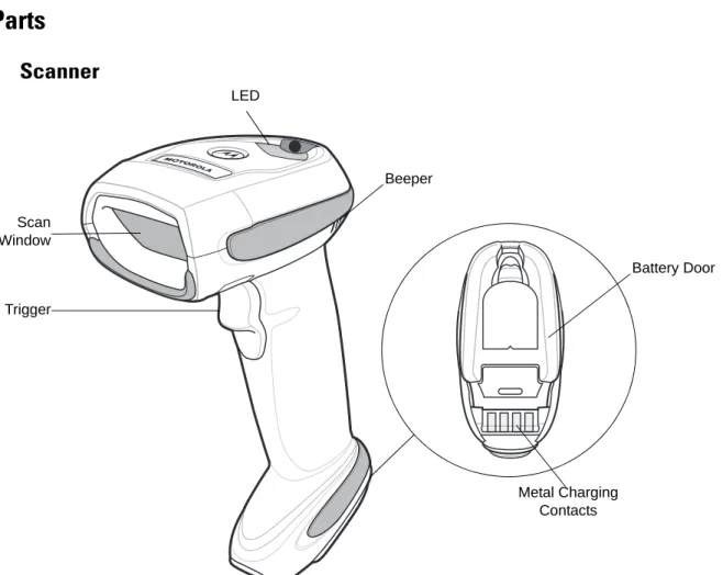
Parts
Scanner
Figure 1-2 Parts of the Linear Imager Scanner Beeper LED Trigger Scan Window Battery Door Metal Charging Contacts
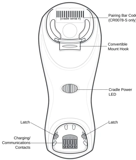
CR0078-S/CR0008-S Series Cradle
Figure 1-3 CR0078-S/CR0008-S Series Cradle Front View
Pairing Bar Code (CR0078-S only) Latch Latch Charging/ Communications Contacts Cradle Power LED Convertible Mount Hook (cradle serial #)
GETTING STARTED
1 - 5
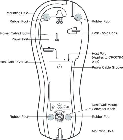
Figure 1-4 CR0078-S/CR0008-S Series Cradle Back View
Rubber Foot Rubber Foot
Mounting Hole Host Cable Groove
Rubber Foot Rubber Foot
Power Port
Host Port
(Applies to CR0078-S only)
Power Cable Groove
Desk/Wall Mount Converter Knob Mounting Hole
CR0078-P Series Cradle
Figure 1-5 CR0078-P Cradle Top View
Figure 1-6 CR0078-P Cradle Bottom View Charging/ Communication Contacts Latch LED Page Button
Rubber Foot Rubber Foot
Rubber Foot Power Port
Host Port Host Cable Groove Power Cable Groove
Host Cable Groove
Cable Support Hook
Cable Support Hook
Mounting Hole Power Cable Groove
Rubber Foot
GETTING STARTED
1 - 7
Linear Imager Scanner Cradle
The scanner cradles (CR0078-S and CR0078-P) serve as a stand, charger, and host interface for the linear imager scanner. The cradle sits on a desktop. The CR0078-S cradle can also be mounted on a vertical surface (such as a wall). For more information about mounting options and procedures, refer to the documentation included with the cradle.
The CR0078-S cradle is available as a charging cradle with a radio and as a charge-only cradle. The
CR0078-P cradle is only available as a charging cradle with a radio. The differences between the two versions are as follows:
•
Charging cradle with radio: When the cordless linear imager scanner is paired to the cradle, all communication between the linear imager scanner and the host computer is accomplished through the cradle. Each bar code contains programming instructions or other data unique to the bar code pattern. The linear imager scanner is paired to the cradle and transmits bar code data to the cradle via Bluetooth Technology Profile Support. The cradle then sends that information via an interface cable to the host computer for interpretation.•
Charge-only cradle: This cradle serves as a stand and battery charger. It does not contain a radio and has no communication capability.Table 1-2 outlines several main differences between the CR0078-S and CR0078-P cradles.
NOTE For more information about communication between the linear imager scanner, cradle and host, see
Chapter 4, RADIO COMMUNICATIONS.
Table 1-2 Cradle Features
Feature CR0078-S CR0078-P
Scanning Hand-Held scanning Hands-Free or Hand-Held scanning Bluetooth Bluetooth or Charge Only (CR0008-S) Bluetooth
Pairing Pair up to 3 scanners per cradle Pair up to seven scanners per cradle Paging Not available Ability to page misplaced scanner(s) Charging Can charge via host power, if available,
or with optional 5V power supply.
Requires 12V power supply
Interfaces Supports most commonly used interfaces (see Technical Specifications on page 3-9 for detailed list)
Supports most commonly used interfaces with the exception of Wand Emulation, Scanner Emulation and Synapse USB Cable Standard universal USB cable Requires universal cables with shielded
Connecting the CR0078-S/CR0008-S Series Cradle
1. If a power supply is connected to the cradle, disconnect it. See Figure 1-7.
2. If using an interface cable (CR0078-S only), insert the cable into the cradle’s host port.
3. If using a power supply that connects to the interface cable (CR0078-S only), insert this power supply into the power connector on the interface cable, and the other end to an AC supply.
4. Insert the other end of the interface cable into the appropriate port on the host computer (see the specific host chapter for information on host connections).
5. If using an external power supply (if required by the interface, or to allow fast charging of the linear imager scanner), insert the power cable into the power port on the back of the cradle, and connect the power supply to an approved AC supply (refer to the CR0078-S/CR0008-S Cradle Quick Reference Guide for more information).
Figure 1-7 Connecting the Cables to the CR0078-S/CR0008-S Cradle
6. If applicable, thread the interface cable over the cable support hook and run the host and power cables into their respective cable grooves.
7. Mount the cradle, as necessary. (For information on mounting the cradle, refer to the documentation included with the cradle.)
Supplying Power to the CR0078-S/CR0008-S Cradle
The CR0078-S/CR0008-S cradle receives power from one of two sources:
•
An external power supply.•
When connected to the host through a host cable that supplies power (CR0078-S only).The cradle detects whether the host or the external supply is supplying power. It always draws power from the external supply when available, regardless of the presence of power from a host.
When the CR0078-S cradle is connected to the host via the USB interface, it can be powered by the USB port instead of an external power supply. Powering from a USB host limits charging. The linear imager scanner charges at a slower rate than when charging from an external power supply.
IMPORTANT Connect the interface cable and power supply (if necessary) in the following order to ensure proper operation of the linear imager scanner and cradle.
Power Port
Host Port
Power Port Host Port
Connect to appropriate host Power
NOTE Disconnect the power supply before changing host cables, or the cradle may not recognize the new host. Different cables are required for different hosts. The connectors illustrated in each host chapter are examples only. The connectors may be different from those illustrated, but the steps to connect the cradle remain the same.
GETTING STARTED
1 - 9
Connecting the CR0078-P Series Cradle
1. Insert the interface cable into the cradle’s host port.
2. Connect the other end of the interface cable to the host.
3. Connect the power supply to the cradle’s power port.
4. Connect the appropriate cable to the power supply and AC power source.
5. Thread the interface cable over the cable support hook (see Chapter 1-6, CR0078-P Cradle Bottom View) and run the host and power cables into their respective cable grooves.
6. If necessary, (for non-autodetected interfaces) scan the appropriate host bar code (refer to the CR0078-S/CR0008-S Cradle Quick Reference Guide for more information).
Figure 1-8 Connecting the Cables to the CR0078-P Cradle
Supplying Power to the CR0078-P Cradle
The CR0078-P cradle receives power from an external power supply.
IMPORTANT Connect the interface cable and power supply in the following order to ensure proper operation of the linear imager scanner and cradle.
Power Port
Host Port
Power Port
Host Port
Connect to appropriate host Power
Alternate Host Groove
Alternate Power Groove
NOTE The CR0078-S cradle has the ability to be powered by the host instead of an external power supply. The CR0078-P can only receive power via an external power supply.
Lost Connection to Host
If scanned data does not transmit to the cradle’s host, ensure that all cables are firmly inserted and the power supply is connected to an appropriate AC outlet. If scanned data still does not transmit to the host, reestablish a connection with the host:
1. Disconnect the power supply from the cradle.
2. Disconnect the host interface cable from the cradle.
3. Wait three seconds.
4. Reconnect the host interface cable to the cradle.
5. Reconnect the power supply to the cradle, if required.
6. Reestablish pairing with the cradle by scanning the pairing bar code.
Mounting the Cradle
For information on mounting the CR0078-S cradle, refer to the documentation included with the cradle.
NOTE The CR0078-S does not always require a power supply whereas the CR0078-P always requires a power supply.
GETTING STARTED 1 - 11
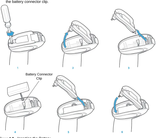
Replacing the Linear Imager Scanner Battery
The battery is installed in the cordless linear imager scanner by the factory and resides in a chamber in the linear imager scanner handle. To replace the battery:
1. Insert a Phillips screwdriver in the screw at the base of the linear imager scanner, then turn the screw counterclockwise to release the latch.
2. Remove the latch.
3. If a battery is already installed, turn the linear imager scanner upright to slide the battery out. Disconnect the battery connector clip.
Figure 1-9 Inserting the Battery
4. With the contacts on the connector clips facing in the same direction, attach the new battery’s connector clip to the connector clip in the base of the linear imager scanner.
5. Slide the new battery into the battery well and ensure the battery leads are visible. The battery should sit securely in the well.
6. Attach and close the latch.
7. Insert a Phillips screwdriver in the screw at the base of the linear imager scanner, press down gently, and turn the screw clockwise to lock the latch in place.
11 5 4 3 2 6 Battery Connector Clip
Charging the Linear Imager Scanner Battery
Fully charge the linear imager scanner battery before using the linear imager scanner for the first time. To charge the linear imager scanner battery, place the linear imager scanner in the cradle, ensuring that the metal contacts on the bottom of the linear imager scanner touch the contacts on the cradle. A complete charge of a fully discharged battery can take typically three hours using external power and typically five hours when powered from a host.
For battery charging LED indicators see Table 1-3 and Table 2-2 on page 2-5. See Table 1-4 on page 1-13 for battery reconditioning LED indicators.
Turning Off the Linear Imager Scanner Battery
To turn off the NiMH battery for long term storage or shipping:1. Scan Battery Off bar code below.
Battery Off
2. To turn the battery back on, place the linear imager scanner in the cradle.
CAUTION To avoid a battery temperature fault, always charge the battery in the linear imager scanner within the recommended temperature of 32° to 104° F (0° to 40° C) nominal, 41° to 95° F (5° to 35° C) ideal.
Table 1-3 Charging LED Definitions
LED Indication Indication
Green - Slow Continuous Flash
Non-critical battery temperature fault. Battery is above or below normal operating temperature.
If this occurs, do not use the linear imager scanner and move the linear imager scanner to a location within normal operating temperature. The linear imager scanner can remain in the cradle while the battery warms or cools to normal operating temperature.
Note: For appropriate charging temperatures, see Table 3-3 on page 3-10. Red & Green -
Continuous Flash
Critical battery temperature fault. Battery is above or below normal operating temperature. If this occurs, do not use the linear imager scanner and move the linear imager scanner to a location within normal operating temperature. The linear imager scanner can remain in the cradle while the battery warms or cools to normal operating temperature.
Note: For appropriate charging temperatures, see Table 3-3 on page 3-10. Green - Fast
Continuous Flash
Linear imager scanner is charging.
Green - Solid Linear imager scanner is fully charged. Red Battery may require pre-charge.
GETTING STARTED 1 - 13
Reconditioning the Linear Imager Scanner Battery
To maintain optimal performance of the linear imager scanner NiMH battery, perform a battery recondition approximately once a year.
To begin the battery recondition cycle:
1. Scan Battery Recondition below.
Battery Recondition
2. Place the linear imager scanner into the cradle.
3. The linear imager scanner must perform two charge cycles to complete the battery reconditioning process (discharge/charge/discharge/charge). See Table 1-4.
Battery Reconditioning LED Definitions
NOTE If the scanner is removed from the cradle during the battery reconditioning cycle, the scanner exits the battery reconditioning mode of operation and returns to the normal mode of battery charging (see
Charging the Linear Imager Scanner Battery on page 1-12). To restart the battery reconditioning cycle, re-scan the Battery Recondition parameter and place the scanner in the cradle.
Table 1-4 Battery Reconditioning LED Definitions
Battery Reconditioning
Mode LED Comments
Discharging Red Flash Time to discharge is approximately 2.5 hours. Charging Green Flash Time to charge is typically 3 hours with an external
power supply.
Reconditioning Complete Green - Solid (always on) The linear imager scanner enters a trickle charge until the linear imager scanner is removed from the cradle.
Note: When the scanner is inserted into the CR0078-S (standard) cradle, the scanner's LED is used as the charging indicator.
When the scanner is inserted into the CR0078-P (presentation) cradle, the cradle's LED is used as the charging indicator.
Inserting the Linear Imager Scanner in the Cradle
Insert the linear imager scanner in the cradle so that the metal contacts on the bottom of the linear imager scanner handle touch the contacts on the cradle. Push the handle lightly to ensure a proper connection, engaging the contacts in the cradle and linear imager scanner. Ensure the desk/wall mount converter knob on the back of the cradle is in the correct position for the horizontal or vertical mounting.
Inserting Linear Imager Scanner in the CR0078-S/CR0008-S Cradle
Horizontal Cradle Mount
When mounting the cradle horizontally, where no fastening is necessary:
1. Ensure the rubber feet are attached to the cradle. These feet provide traction and prevent surface damage.
2. Ensure the desk/wall mount converter knob is in the position shown in Figure 1-10.
Figure 1-10 Horizontal Mount - Inserting the Linear Imager Scanner in the Cradle
Vertical Cradle Mount
When mounting the cradle vertically:
1. Ensure the rubber feet are attached to the cradle. These feet provide traction and prevent surface damage.
2. Ensure the convertible mount hook on the front of the cradle is inserted with the hook facing up. If not, remove and reverse the hook so that it is in position to secure the linear imager scanner in place. (See Figure 1-3 on page 1-4 for the location of the convertible mount hook.)
NOTE References to mounting the cradle only apply to the CR0078-S/CR0008-S cradle (not the CR0078-P cradle).
Desk/Wall Mount Converter Knob
GETTING STARTED 1 - 15
3. Ensure the desk/wall mount converter knob is in the position shown in Figure 1-11.
Figure 1-11 Vertical Mount - Inserting the Linear Imager Scanner in the Cradle
Inserting/Removing Linear Imager Scanner in the CR0078-P Cradle
To insert the scanner in the Presentation Cradle:
1. Insert the scanner by placing the bottom of the scanner, at a slight forward angle, into the CR0078-P cradle.
2. Push the handle back and down until it clicks, engaging the contacts of the scanner and cradle.
Figure 1-12 Inserting the Linear Imager Scanner in the Presentation Cradle To remove the scanner from the Presentation Cradle:
1. Remove the scanner by pushing the scanner slightly forward and up out of the CR0078-P cradle.
Desk/Wall Mount Converter Knob Click 1 2
Figure 1-13 Removing the Linear Imager Scanner in the Presentation Cradle 1
2
GETTING STARTED 1 - 17
Wall Mount Bracket Template
For your convenience, a wall mount bracket can be purchased from Motorola. Use the mounting holes on the Wall Mount Bracket or use the template in Figure 1-14 to determine the location of the screw holes.
Figure 1-14 Wall Mount Bracket Template
7.55 in . (191 .7 7mm) 1.7 in. (43.18mm)
NOTE Cradle mounting only applies to the
CR0078-S/CR0008-S cradle (not the CR0078-P cradle). For detailed instructions on mounting the cradle, refer to the CR0078-S/CR0008-S Quick Reference Guide (p/n 72-135874-xx).
Radio Communications
The linear imager scanner can communicate with remote devices via Bluetooth Technology Profile Support, or by pairing with a cradle. For radio communication parameters, detailed information about operational modes, Bluetooth Technology Profile Support and pairing, see Chapter 4, RADIO COMMUNICATIONS.
Configuring the Linear Imager Scanner
Use the bar codes in this manual or the 123Scan2configuration program to configure the linear imager scanner. See Chapter 5, USER PREFERENCES & MISCELLANEOUS SCANNER OPTIONS for information about programming the linear imager scanner using bar code menus. Also see each host-specific chapter to set up connection to a specific host type. See Chapter 10, 123SCAN2 to configure the linear imager scanner using this configuration program.
Accessories
The linear imager scanner and cradle accessories that are available separately include:
•
Power supplies for applications that do not supply power over the host cable. See each host interface chapter for set up information.•
Wall-mount bracket for mounting the cradle vertically. Refer to the CR0078-S/CR0008-S Cradle Quick Reference Guide (p/n 72-135874-xx) for a wall mounting template and installation instructions.•
Lanyard for wearing the linear imager scanner on a wrist.Lanyard
The lanyard attaches to the inside of the linear imager scanner battery door latch.
GETTING STARTED 1 - 19
To attach the lanyard:
1. Open the battery door latch as described in Replacing the Linear Imager Scanner Battery on page 1-11. Do not remove the battery.
2. Hook the loop of the lanyard around the screw container inside the battery door latch, between the loop guides.
Figure 1-16 Attaching Lanyard
3. Close the battery door latch.
4. Tighten the screw.
Battery Door Latch
Loop Guides
CHAPTER 2 SCANNING
Introduction
This chapter provides beeper and LED definitions, scanning techniques, general instructions and tips about scanning, and decode ranges.
Beeper and LED Definitions
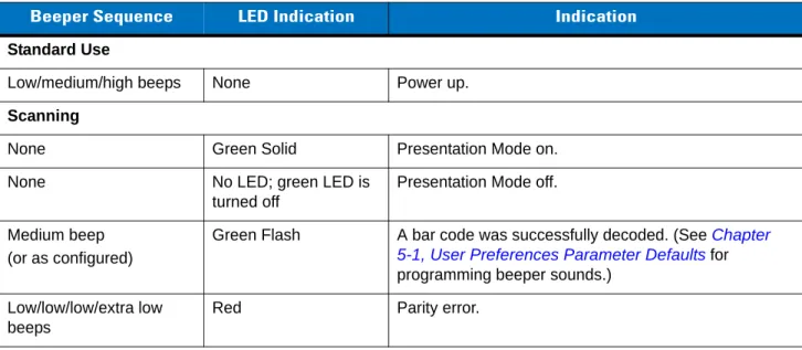
The linear imager scanner issues different beep sequences/patterns and an LED display to indicate status. Table 2-1 defines beep sequences/patterns and LED displays which occur during both normal scanning and while programming the linear imager scanner. (Also seeTable 1-3 on page 1-12 and Table 1-4 on page 1-13 for charging and battery reconditioning LED indicators.)
Table 2-1 Scanner Beeper and LED Definitions
Beeper Sequence LED Indication Indication
Standard Use
Low/medium/high beeps None Power up.
Scanning
None Green Solid Presentation Mode on.
None No LED; green LED is
turned off
Presentation Mode off.
Medium beep (or as configured)
Green Flash A bar code was successfully decoded. (See Chapter 5-1, User Preferences Parameter Defaults for programming beeper sounds.)
Low/low/low/extra low beeps
Four long low beeps Red 1. A transmission error was detected in a scanned symbol. The data is ignored. This occurs if a unit is not properly configured. Check option setting.
2. When communicating with a cradle, the cradle acknowledges receipt of data. If the acknowledgment is not received, this transmission error beep sequence sounds. Data may still have been received by the host. Check the host system for receipt of transmitted data. If data was not received by the host, re-scan the bar code. Four short high beeps None Low battery warning.
Five long low beeps Red Conversion or format error. Long low/long high/long
low/long high beeps
Red Out of memory - unable to store a new bar code.
Wireless Operation
Low beep None Linear imager scanner detects power when inserted into a cradle.
Note: This feature is enabled by default and can be disabled (see Beep on Insertion on page 4-17). Long low/long high/long
low/long high beeps
Red Cradle is out of batch storage memory, unable to store new bar code.
High/low/high/low beeps None Pairing bar code scanned. Low/high beeps None Bluetooth connection established. High/low beeps None Bluetooth disconnection event.
Note: When connected to a remote device using SPP or HID, if a disconnect beep sequence sounds immediately after a bar code is scanned, check the host device for receipt of transmitted data. It is possible that an attempt was made to transmit the last bar code scanned after the connection was lost.
Long low/long high beeps Red Page timeout; remote device is out of range/not powered. (See Auto-reconnect Feature on page 4-13.) Five high beeps
(only when configured)
Green Blinking 1. Bluetooth attempting reconnection.
2. Emitted every 5 seconds while a reconnection attempt is in progress. (See Auto-reconnect Feature on page 4-13.)
Table 2-1 Scanner Beeper and LED Definitions (Continued)
SCANNING
2 - 3
Long low/long high/long low/long high beeps
None Connection attempt was rejected by remote device. Note: In the case of Pairing Methods on page 4-21, the cradle may already be connected to another linear imager scanner in single Point-to-Point locked mode, or the piconet may be full in Multipoint-to-Point mode. If Pair On Contacts is enabled and the linear imager scanner that is inserted is already connected to the cradle, no beeping occurs.
Parameter Programming
Long low/long high beeps Red Input error, incorrect bar code or Cancel scanned, wrong entry, incorrect bar code programming sequence; remain in program mode.
High/low beeps Green Keyboard parameter selected. Enter value using bar code keypad.
High/low/high/low beeps Green Successful program exit with change in the parameter setting.
ADF Programming
Low/high/low beeps None ADF transmit error.
High/low beeps Green Number expected. Enter another digit. Add leading zeros to the front if necessary.
Low/low beeps Green Alpha expected. Enter another alphabetic character or scan the End of Message bar code.
High/high beeps Green Blinking ADF criteria or action is expected. Enter another criteria or action or scan the Save Rule bar code.
High/low/low beeps Green All criteria or actions cleared for current rule, continue entering rule.
High/low/high/low beeps Green
(turns off blinking)
Rule saved. Rule entry mode exited.
Long low/long high beeps Red Rule error. Entry error, wrong bar code scanned, or criteria/action list is too long for a rule. Re-enter criteria or action.
Low beep Green Deleted last saved rule. The current rule is left intact. Low/high/high beeps Green All rules deleted.
Long low/long high/long low/long high beeps
Red Out of rule memory. Erase some existing rules, then try to save rule again.
Long low/long high/long low beeps
Green
(turns off blinking)
Cancel rule entry. Rule entry mode exited because of an error or the user asked to exit rule entry.
Code 39 Buffering
High/low beeps None New Code 39 data was entered into the buffer. Table 2-1 Scanner Beeper and LED Definitions (Continued)
Three long high beeps None Code 39 buffer is full.
High/low/high beeps None The Code 39 buffer was erased/cleared.
Low/high/low beeps None The Code 39 buffer was erased or there was an attempt to clear or transmit an empty buffer.
Low/high beeps None A successful transmission of buffered data.
Host Specific USB only
Four high beeps None Linear imager scanner has not completed initialization. Wait several seconds and scan again.
RS-232 only
High/high/high/low beeps Red RS-232 receive error.
High beep None A <BEL> character is received when Beep on <BEL> is enabled (Point-to-Point mode only).
Table 2-1 Scanner Beeper and LED Definitions (Continued)
SCANNING
2 - 5
Cradle LED Definitions
IMPORTANT When the scanner is inserted into the CR0078-S (standard) cradle, the scanner's LED is used as the charging indicator.
When the scanner is inserted into the CR0078-P (presentation) cradle, the cradle's LED is used as the charging indicator.
NOTE The CR0078-S/CR0008-S cradles’ LED indicate power only.
Table 2-2 CR0078-P Cradle LED Definitions
LED Indication
Green Blinking Cradle is externally powered and connected to a USB host interface which has suspended the cradle. The cradle is no longer connected to the linear imager scanner but it will charge the linear imager scanner. Scan the pairing bar code to pair the scanner and cradle (see Pairing on page 4-19).
Red Blinking Transmission error.
Green Cradle is powered.
Red Blinking Transmission error.
Green Slow Blinking Non-critical battery temperature fault. Green Slow Blinking Charging in cradle with USB (bus powered). Green Fast Blinking The scanner is charging.
Amber Blinking Critical battery temperature fault. Green Solid The scanner is fully charged. Red Solid Battery requires precharge. Red Slow Blinking Battery is reconditioning.
Scanning
To program the linear imager scanner, see the appropriate host chapter, Chapter 4, RADIO
COMMUNICATIONS and Chapter 11, SYMBOLOGIES. (In addition to the parameters included in the chapters mentioned, user preference and miscellaneous linear imager scanner option parameters are also available in this guide.)
Aiming
When scanning, the linear imager scanner projects a red illumination which allows positioning the bar code within its field of view. See Decode Ranges on page 2-8 for the proper distance to achieve between the linear imager scanner and a bar code.
Hand-Held Scanning
To scan:
1. Ensure all connections are secure (see appropriate host chapter).
2. Aim the linear imager scanner at the bar code.
3. Press the trigger.
Figure 2-1 Scanning
4. Upon successful decode, the linear imager scanner beeps and the LED displays a single green flash. (For more information about beeper and LED definitions, see Table 2-1 and Table 2-2.)
SCANNING
2 - 7
Hands-Free Scanning
The linear imager scanner is in hands-free (presentation) mode when it sits in the CR0078-P cradle. In this mode the linear imager scanner operates in continuous (constant-on) mode, where it automatically decodes a bar code presented in the field of view. The scanner LED is on, solid green
To scan:
1. Ensure all connections are secure (see appropriate host chapter).
2. Present the bar code in the linear imager scanner field of view.
Figure 2-2 Presentation Scanning
3. Upon successful decode, the linear imager scanner beeps and the green LED momentarily turns off. (For more information about beeper and LED definitions, see Table 2-1 and Table 2-2.)
Decode Ranges
Ranges are calculated on Code 39 except where noted. Table 2-3 LI4278 Decode Ranges
Symbol Density Bar Code Type
Typical Working Ranges Near Far
4 mil Code 39 4 in. (10.2 cm) 10.0 in. (25.4 cm) 5 mil Code 39 3.0 in. (7.6 cm) 13.0 in. (33.0 cm) 7.5 mil Code 39 1.5 in. (3.8 cm) 19.0 in. (48.3 cm) 13 mil 100% UPC-A 1.0 in. (2.5 cm) 31.0 in. (78.7 cm) 20 mil Code 39 1.0 in. (2.5 cm) 42.0 in. (106.7 cm) 26 mil 200% UPC-A 3.0 in. (7.6 cm) 55.0 in. (140.0 cm)
100 mil (paper) > 20 ft. (> 6 m)
NOTE When reading high density bar codes, users should attempt to read them slightly farther away from the scanner. Typically a 3 mil Code39 bar code begins reading at 5 in. (12.8cm).
CHAPTER 3 MAINTENANCE,
TROUBLESHOOTING &
TECHNICAL SPECIFICATIONS
Introduction
This chapter provides suggested linear imager scanner and cradle maintenance, troubleshooting, technical specifications, and signal descriptions (pinouts).
Maintenance
Known Harmful Ingredients
The following chemicals are known to damage the plastics on Motorola scanners/cradles and should not come in contact with the device:
• Acetone
• Ammonia solutions
• Aqueous or alcoholic alkaline solutions • Aromatic and chlorinated hydrocarbons • Benzene
• Bleach • Carbolic acid
• Compounds of amines or ammonia • Ethanolamine • Ethers • Ketones • TB-lysoform • Toluene • Trichloroethylene.
Approved Cleaning Agents
The following cleaning agents are approved for cleaning the plastics on Motorola scanners/cradles: • Pre-moistened wipes