D-Link
™
DGS-3100 SERIES
GIGABIT STACKABLE MANAGED SWITCH
CLI Manual
Information in this document is subject to change without notice. © 2009 D-Link Computer Corporation. All rights reserved.
Reproduction in any manner whatsoever without the written permission of D-Link Computer Corporation is strictly forbidden.
Trademarks used in this text: D-Link and the D-Link logo are trademarks of D-Link Computer Corporation; Microsoft and Windows are registered trademarks of Microsoft Corporation.
Other trademarks and trade names may be used in this document to refer to either the entities claiming the marks and names or their products. D-Link Computer Corporation disclaims any proprietary interest in trademarks and trade names other than its own.
FCC Warning
This equipment has been tested and found to comply with the limits for a Class A digital device, pursuant to Part 15 of the FCC Rules. These limits are designed to provide reasonable protection against harmful interference when the equipment is operated in a commercial environment. This equipment generates, uses, and can radiate radio frequency energy and, if not installed and used in accordance with this user’s guide, may cause harmful interference to radio communications. Operation of this equipment in a residential area is likely to cause harmful interference in which case the user will be required to correct the interference at hisown expense.
CE Mark Warning
This is a Class A product. In a domestic environment, this product may cause radio interference in which case the user may be required to take adequate measures.
Warnung!
Dies ist ein Produkt der Klasse A. Im Wohnbereich kann dieses Produkt Funkstoerungen verursachen. In diesem Fall kann vom Benutzer verlangt werden, angemessene Massnahmen zu ergreifen.
Precaución!
Este es un producto de Clase A. En un entorno doméstico, puede causar interferencias de radio, en cuyo case, puede requerirse al usuario para que adopte las medidas adecuadas.
Attention!
Ceci est un produit de classe A. Dans un environnement domestique, ce produit pourrait causer des interférences radio, auquel cas l`utilisateur devrait prendre les mesures adéquates.
Attenzione!
Il presente prodotto appartiene alla classe A. Se utilizzato in ambiente domestico il prodotto può causare interferenze radio, nel cui caso è possibile che l`utente debba assumere provvedimenti adeguati.
VCCI Warning
INTRODUCTION ...1
USING THE CONSOLE CLI...4
COMMAND SYNTAX ...8
BASIC SWITCH COMMANDS...11
create account... 12
config account... 13
show account... 13
show session... 14
show system defaults ... 14
show switch... 15 show serial_port ... 16 config serial_port ... 16 enable clipaging ... 17 disable clipaging ... 18 delete account... 18 enable web ... 18 disable web... 19 save ... 19 reboot ... 20 reset... 20 login ... 21 logout ... 21 ping ... 22 show configuration... 22 enable jumbo_frame... 23 disable jumbo_frame... 24 show jumbo_frame... 24 locate... 24 telnet... 25 enable telnet ... 25 disable telnet ... 26 enable dhcp_relay ... 26 disable dhcp_relay... 26
config dhcp_relay add ipif ... 27
config dhcp_relay delete ipif... 27
show dhcp_relay ipif... 27
show tech_support... 28
show environment... 29
config time_range ... 30
show time_range ... 30
config terminal log... 31
show cable status... 31
SWITCH PORT COMMANDS...33
config ports ... 33
config ports description... 35
delete ports description ... 35
show ports description ... 35
NETWORK MANAGEMENT (SNMP) COMMANDS ...37
create snmp user... 38 delete snmp user... 39 show snmp user... 39 create snmp view... 40 delete snmp view... 40 show snmp view... 41 create snmp community ... 42 delete snmp community ... 42 show snmp community ... 43 config snmp engineID... 43 show snmp engineID... 44 create snmp group ... 44 delete snmp group ... 46 show snmp groups... 46 create snmp host... 47 delete snmp host... 48 show snmp host... 48 create trusted_host... 49 show trusted_host... 50 delete trusted_host... 50 enable snmp traps... 50 disable snmp traps... 51
enable snmp authenticate trap ... 51
disable snmp authenticate trap ... 52
show snmp traps... 52 config snmp system_contact ... 52 config snmp system_location... 53 config snmp system_name ... 53 enable snmp ... 54 disable snmp... 54 DOWNLOAD/UPLOAD COMMANDS ...55 download... 55 upload... 56
config dhcp_auto enable ... 57
show dhcp_auto... 57
config firmware... 58
show firmware information... 58
DHCP LOCAL RELAY ...59
config dhcp_local_relay state... 59
config dhcp_local_relay vlan ... 59
NETWORK MONITORING COMMANDS ...61
show packet ports... 61
clear counters ... 64 clear log... 64 show log... 64 enable syslog... 65 disable syslog ... 65 show syslog... 66
create syslog host ... 66
config syslog host... 68
delete syslog host ... 70
show syslog host ... 71
clear green-ethernet Cumulative_Energy_Saved ... 71
show green-ethernet ... 72
SPANNING TREE COMMANDS...73
config stp... 73 config stp ports... 74 config stp version... 76 enable stp ... 76 disable stp... 76 show stp ... 77 show stp ports ... 78 show stp instance_id ... 79 show stp mst_config_id ... 79 config stp instance_id... 80 config stp priority... 81 config stp mst_config_id... 81 config stp mst_ports ... 82
FORWARDING DATABASE COMMANDS...84
create fdb... 84 create multicast_fdb ... 85 config multicast_fdb ... 85 config fdb aging_time ... 86 delete fdb... 86 clear fdb ... 87 show multicast_fdb ... 87 show fdb... 88
config multicast filtering_mode ... 89
show multicast filtering_mode... 89
config dlf filtering_mode ... 90
show dlf filtering_mode ... 90
BROADCAST STORM CONTROL COMMANDS ...92
config traffic control ... 92
show traffic control ... 93
config traffic trap ... 94
config traffic control_recover ... 94
QOS COMMANDS ...95
show scheduling... 96 config bandwidth_control ... 97 show bandwidth_control ... 97 config 802.1p user_priority... 98 show 802.1p user_priority... 99 config 802.1p default_priority ... 100 show 802.1p default_priority ... 100 config scheduling_mechanism ... 101 show scheduling_mechanism... 102 config rate_limit... 102 show rate_limit... 103 config dscp user_priority ... 104 show dscp user_priority ... 104
PORT MIRRORING COMMANDS ...106
config mirror ... 106 delete mirror... 107 show mirror... 107 VLAN COMMANDS ...108 create vlan ... 108 delete vlan ... 109 config vlan ... 109 config gvrp ... 110 enable gvrp... 111 disable gvrp... 111 show vlan ... 111 show gvrp... 112 enable vlan_trunk... 113 disable vlan_trunk... 113 show vlan_trunk... 113
config vlan_trunk ports ... 114
enable asymmetric_vlan... 114
disable asymmetric_vlan... 115
show asymmetric_vlan... 115
config voice_vlan... 116
show voice vlan... 116
LINK AGGREGATION COMMANDS ...118
create link_aggregation ... 118
delete link_aggregation ... 119
config link_aggregation ... 119
show link_aggregation ... 120
BASIC IP COMMANDS...121
config ipif system... 121
show ipif... 122
IGMP SNOOPING COMMANDS...123
config igmp_snooping... 123
config igmp_snooping querier ... 124
enable igmp_snooping ... 125
disable igmp_snooping ... 126
show igmp_snooping ... 126
show igmp_snooping group ... 127
show igmp_snooping forwarding... 127
show router_port ... 128
MLD SNOOPING COMMANDS...129
enable mld_snooping ... 129
disable mld_snooping ... 130
config mld_snooping... 130
config mld_snooping mrouter_port... 131
config mld_snooping mrouter_port_forbidden ... 131
show mld snooping ... 132
show mld_snooping forwarding... 132
show mld_snooping groups... 133
show mld_snooping mrouter_port ... 133
802.1X COMMANDS...135 enable 802.1x ... 136 disable 802.1x ... 136 config 802.1x ... 136 show 802.1x auth_state ... 137 show 802.1x auth_configuration... 138
config 802.1x auth_parameter ports... 139
config 802.1x init ... 140
config 802.1x auth_protocol ... 140
config 802.1x reauth ... 141
config radius add... 141
config radius delete ... 142
config radius... 142
show radius ... 143
config 802.1x auth_mode... 143
create 802.1x guest_vlan... 144
delete 802.1x guest_vlan... 144
config 802.1x guest_vlan ports ... 145
config 802.1x radius attribute ... 145
show 802.1x guest_vlan... 146
MAC AUTHENTICATION COMMANDS...147
enable mac_based_access_control ... 147
disable mac_based_access_control ... 148
config mac_based_access_control ... 148
show mac_based_access_control ... 149
PORT SECURITY COMMANDS...150
config port_security ... 151
show port_security ... 152
TIME AND SNTP COMMANDS ...153
show sntp ... 154
enable sntp ... 154
disable sntp... 155
config time date... 155
config time_zone... 156
config dst... 156
show time ... 158
ROUTING TABLE COMMANDS ...159
create iproute... 159 delete iproute... 159 show iproute... 160 ARP COMMANDS...161 create arpentry... 161 config arpentry ... 161 delete arpentry... 162 show arpentry... 163
config arp_aging time ... 163
clear arptable... 164
config arp_spoofing_prevention ... 164
show arp_spoofing_prevention ... 165
BANNER COMMANDS...166
config login_banner ... 166
COMMAND HISTORY LIST COMMANDS ...167
?... 167 show command_history ... 168 dir ... 168 config command_history... 169 SSH COMMANDS...170 enable ssh ... 170 disable ssh ... 171 config ssh authmode... 171 show ssh authmode ... 171 config ssh server... 172 show ssh server ... 172 show ssh algorithm... 173 config ssh crypto ... 173 show ssh crypto... 174 delete ssh crypto... 175 SSL COMMANDS ...176 enable ssl... 176 disable ssl... 177 show ssl... 177 show ssl cachetimeout... 178
crypto certificate (generate) ... 178
crypto certificate (request) ... 179
crypto certificate (import) ... 180
ACCESS AUTHENTICATION CONTROL COMMANDS ...182
create authen_login method_list_name... 183
config authen_login... 183
delete authen_login method_list_name... 184
show authen_login ... 185
create authen_enable method_list_name... 185
config authen_enable ... 186
delete authen_enable method_list_name... 187
show authen_enable ... 188
config authen application ... 188
show authen application... 189
create authen server_host ... 190
config authen server_host ... 191
delete authen server_host ... 192
show authen server_host ... 192
local_enable admin ... 193
config admin local_enable ... 193
LACP COMMANDS ...195
config lacp port_priority ... 195
show lacp ... 195 LLDP COMMANDS...197 enable lldp (global) ... 197 disable lldp (global) ... 198 enable lldp forward_message... 198 disable lldp forward_message ... 199 config lldp message_tx_interval ... 199 config lldp message_tx_hold_multiplier... 199 config lldp reinit_delay ... 200 config lldp tx_delay ... 200 show lldp... 201 show lldp ports... 201 show lldp local_ports ... 202 show lldp remote_ports... 202 config lldp ports ... 203 STACKING COMMANDS ...206 config box_id ... 206 show stack_information ... 206 POE COMMANDS...208 config poe... 208
config poe ports... 209
show poe ... 210
ACCESS CONTROL LIST COMMANDS ...211
create access_profile (for Ethernet)... 212
create access_profile (for IPv4) ... 212
create access_profile (for IPv6) ... 214
config access_profile (for IPv4)... 217
config access_profile (for IPv6)... 219
config access_profile... 221
delete access_profile ... 222
show access_profile ... 222
TRAFFIC SEGMENTATION COMMANDS...224
config traffic_segmentation ... 224 show traffic_segmentation ... 224 TRACEROUTE COMMANDS ...226 traceroute... 226 SAFEGUARD COMMANDS ...228 config safeguard_engine ... 228 show safeguard_engine ... 229 DEVICE SPECIFICATIONS ...230 Technical Specifications ... 230 Cable Lengths ... 232
1
INTRODUCTION
The DGS-3100 series of products family consists of 24 / 48 -port 10/100/1000Base-T PoE / NonPoE L2 Stackable Management Switches with 4 Combo SFPs and DGS-3100-24TG, a switch with 16 SFPs and 8 copper GE ports.The Switch can be managed through the Switch’s serial port, Telnet, or the Web-based management agent. The Command Line Interface (CLI) can be used to configure and manage the Switch via the serial port or Telnet interfaces.
This manual provides a reference for all of the commands contained in the CLI. Configuration and management of the Switch via the Web-based management agent is discussed in the Manual. For detailed information on installing hardware please refer also to the Manual.
Accessing the Switch via the Serial Port
The Switch’s serial port’s default settings are as follows: 9600 bps
No parity 8 data bits
1 stop bit
A computer running a terminal emulation program capable of emulating a VT-100 terminal and a serial port configured as above is then connected to the Switch’s serial port via an RS-232 DB-9 cable.
With the serial port properly connected to a management computer, the following screen should be visible. If this screen does not appear, try pressing Ctrl+r to refresh the console screen.
[ Figure 1–1 Initial CLI screen
The initial username is admin (lower case). Press the Enter key twice to display the CLI input cursor. This is the command line where all commands are input.
Setting the Switch’s IP Address
Each Switch must be assigned its own IP Address, which is used for communication with an SNMP network manager or other TCP/IP application (for example BOOTP, TFTP). The Switch’s default IP address is 10.90.90.90. You can change the default Switch IP address to meet the specification of your networking address scheme.
The Switch is also assigned a unique MAC address by the factory. This MAC address cannot be changed, but can be found on the initial boot console screen – shown below.
Figure 1–2 Boot Screen
The Switch’s MAC address can also be found in the Web management program on the Device Information window on the Configuration menu.
The IP address for the Switch must be set before it can be managed with the Web-based manager. The Switch IP address can be automatically set using BOOTP or DHCP protocols, in which case the actual address assigned to the Switch must be known.
The IP address may be set using the Command Line Interface (CLI) over the console serial port as follows:
1. Starting at the command line prompt, enter the commands config ipif System vlan default ipaddress
xxx.xxx.xxx.xxx/yyy.yyy.yyy.yyy. Where the letter x represents the IP address to be assigned to the IP interface named System and the letter y represents the corresponding subnet mask.
2. Alternatively, enter config ipif System ipaddress xxx.xxx.xxx.xxx/z. Where the letter x represents the IP address to be assigned to the IP interface named System and the letter z represents the corresponding number of subnets in CIDR notation.
The IP interface named System on the Switch can be assigned an IP address and subnet mask which can then be used to connect a management station to the Switch’s Telnet or Web-based management agent.
In the above example, the Switch was assigned an IP address of 1.1.1.10 with a subnet mask of 255.0.0.0. The system message Success indicates that the command was executed successfully. The Switch can now be configured and managed via Telnet, SNMP MIB browser and the CLI or via the Web-based management agent using the above IP address to connect to the Switch.
NOTE: The DGS-3100 series of switches have the capability to be configured to have no IP address. This function maybe used to disable Layer 3 functions of the Switch. When the IP address is disabled, the Switch can only be managed through the console port. Other
management applications such as Telnet, Web-based and SNMP cannot be used to manage the Switch when the switch has no IP address.
2
USING THE CONSOLE CLI
The Switch supports a console management interface that allows the user to connect to the Switch’s management agent via a serial port and a terminal or a computer running a terminal emulation program. The console can also be used over the network using the TCP/IP Telnet protocol. The console program can be used to configure the Switch to use a SNMP-based network management software over the network.This chapter describes how to use the console interface to access the Switch, change its settings, and monitor its operation.
NOTE: Switch configuration settings are saved to non-volatile RAM using the save command. The current configuration will then be retained in the Switch’s NV-RAM, and reloaded when the Switch is rebooted. If the Switch is rebooted without using the save command, the last
configuration saved to NV-RAM is loaded.
Connecting to the Switch
The console interface is used by connecting the Switch to a VT100-compatible terminal or a computer running an ordinary terminal emulator program (for example, the HyperTerminal program included with the Windows operating system) using an RS-232C serial cable. Your terminal parameters will need to be set to:
VT-100 compatible 9600 bps
8 data bits No parity One stop bit No flow control
The same functions may also be accessed over a Telnet interface. Once an IP address for the Switch has been set, A Telnet program can be used (in VT-100 compatible terminal mode) to access and control the Switch. All of the screens are identical, whether accessed from the console port or from a Telnet interface.
Figure 2–1 Initial Console Screen after Logging In Commands are entered at the command prompt, DGS3100#.
There are a number of helpful features included in the CLI. Entering the ? command displays a list of all of the top-level commands.
Figure 2–2 The ? Command
When entering a command without its required parameters, the CLI displays the prompt: command: config account message and the options listed below.
Figure 2–3 Example Command Parameter Help
In this case, the command config account was entered with the parameter <username>. The CLI will then prompt to enter the <username> with the message, command: config account. Every command in the CLI has this feature, and complex commands have several layers of parameter prompting.
In addition, after typing any given command plus one space, users can see all of the next possible sub-commands, in sequential order, by pressing the ? key.
To re-enter the previous command at the command prompt, press the up arrow cursor key. The previous command appears at the command prompt.
Figure 2–4 Using the Up Arrow to Re-enter a Command
In the above example, the command config account was entered without the required parameter <username>, the CLI returned the command: config account prompt. The up arrow cursor control key was pressed to re-enter the previous command (config account) at the command prompt. Now the appropriate username can be entered and the config account command re-executed.
All commands in the CLI function in this way. In addition, the syntax of the help prompts are the same as presented in this manual angle brackets < > indicate a numerical value or character string. The < > can also indicate a word with a number for character allowed.
If a command is entered that is unrecognized by the CLI, the top-level commands are displayed under the Available commands: prompt.
Figure 2–5 Available Commands
The top-level commands consist of commands such as show or config. Most of these commands require one or more parameters to narrow the top-level command. This is equivalent to show what? or config what? Where the what? is the next parameter.
For example, entering the show command with no additional parameters, the CLI will then display all of the possible next parameters.
Figure 2–6 Next possible completions: Show Command
In the above example, all of the possible next parameters for the show command are displayed. At the next command prompt in the example, the up arrow was used to re-enter the show command, followed by the account parameter. The CLI then displays the user accounts configured on the Switch.
3
COMMAND SYNTAX
The following symbols are used to describe how command entries are made and values and arguments are specified in this manual. The online help contained in the CLI and available through the console interface uses the same syntax.NOTE: All commands are case-sensitive. Be sure to disable Caps Lock or any other unwanted function that changes text case.
<angle brackets>
Purpose Encloses a variable or value that must be specified. Syntax create account [admin | oper |user] <username 15>
Description In the above syntax example, supply a username in the <username> space. Do not type the angle brackets. Example
Command create account admin newadmin1
[square brackets]
Purpose Encloses a required value or set of required arguments. One value or argument can be specified.
Syntax create account [admin | oper |user] <username 15>
Description In the above syntax example, specify admin, oper or a user level account to be created. Do not type the square brackets.
Example
Command create account user newuser1
| vertical bar
Purpose Separates two or more mutually exclusive items in a list, one of which must be entered.
Syntax create account [admin | oper | user] <username 15>
Description In the above syntax example, specify admin, oper, or user. Do not type the vertical bar.
Example
Command create account user newuser1
All commands are case-sensitive. Be sure to disable Caps Lock or any other unwanted function that changes text case.
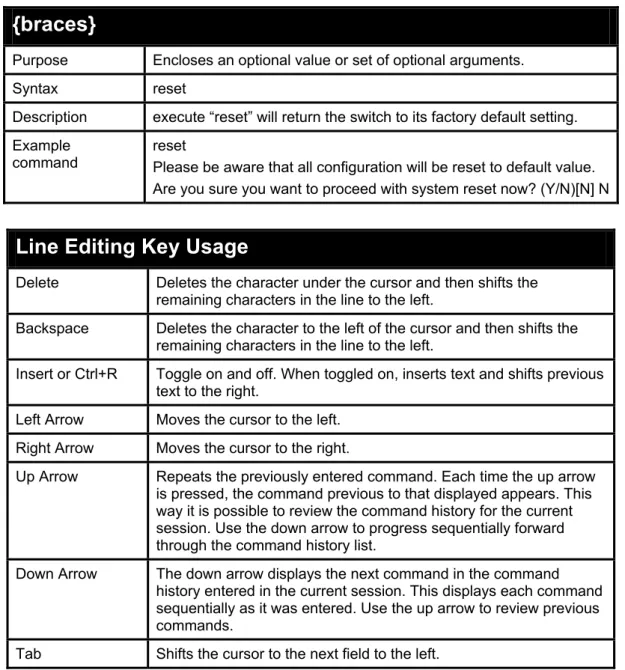
{braces}
Purpose Encloses an optional value or set of optional arguments. Syntax reset
Description execute “reset” will return the switch to its factory default setting. Example
command reset Please be aware that all configuration will be reset to default value. Are you sure you want to proceed with system reset now? (Y/N)[N] N
Line Editing Key Usage
Delete Deletes the character under the cursor and then shifts the remaining characters in the line to the left.
Backspace Deletes the character to the left of the cursor and then shifts the remaining characters in the line to the left.
Insert or Ctrl+R Toggle on and off. When toggled on, inserts text and shifts previous text to the right.
Left Arrow Moves the cursor to the left. Right Arrow Moves the cursor to the right.
Up Arrow Repeats the previously entered command. Each time the up arrow is pressed, the command previous to that displayed appears. This way it is possible to review the command history for the current session. Use the down arrow to progress sequentially forward through the command history list.
Down Arrow The down arrow displays the next command in the command history entered in the current session. This displays each command sequentially as it was entered. Use the up arrow to review previous commands.
Multiple Page Display Control Keys
Space Displays the next page.
CTRL+c Stops the display of remaining pages when multiple pages are to be displayed.
ESC Stops the display of remaining pages when multiple pages are to be displayed.
n Displays the next page. p Displays the previous page.
q Stops the display of remaining pages when multiple pages are to be displayed.
r Refreshes the pages currently displayed.
a Displays the remaining pages without pausing between pages. Enter Displays the next line or table entry.
4
BASIC SWITCH COMMANDS
The Basic Switch commands in the Command Line Interface (CLI) are listed (along with the appropriate parameters) in the following table.Command
Parameter
create account [admin | oper | user] <username 15>{password <password_string> {encrypted}} config account <username 15>
show account show session
show system_defaults show switch
show serial_port
config serial_port {baud_rate [2400 | 4800 | 9600 | 19200 | 38400] auto_logout [never | 2_minutes | 5_minutes| 10_minutes | 15_minutes]} enable clipaging
disable clipaging
delete account <username 15>
enable web <tcp_port_number 1-65535> disable web save reboot <box_id 1-6> reset login logout
ping <ipaddr> {times <value 1-255>} {timeout <sec 1-99>}
show configuration [running {include <token> {include <token> | <token>}} | startup] enable jumbo_frame
disable jumbo_frame show jumbo_frame locate
telnet {ip-address | hostname} [port] enable telnet
Command
Parameter
disable telnet enable dhcp_relay disable dhcp_relay config dhcp_relay add
ipif <ipaddr> config dhcp_relay
delete ipif <ipaddr> show dhcp_relay ipif <ipaddr>
show tech-support show tech_support [config | memory] show environment
config time_range <range_name 32> [hours start_time <time hh:mm> end_time <time hh:mm> weekdays <daylist> | delete] show time_range
Config terminal log [enable | disable] show cable status <portlist>
Each command is listed in detail, as follows:
create account
Purpose To create user accounts.
Syntax create account [admin | oper | user] <username 15>{password <password_string> {encrypted}}
Description The create account command creates an administrator, operator, or user account that consists of a username and an optional password. Up to 31 accounts can be created. You can enter username and Enter. In this case, the system prompts for the account’s password, which may be between 0 and 15 characters. Alternatively, you can enter the username and password on the same line.
Parameters admin − creates an administrator account. oper − creates an operator account.
user − creates a user account with read-only permissions.
<username 1-15> − The account username may be between 1 and 15 characters.
password <password_string> {encrypted} - the account password can be included, and (optionally) can be encrypted.
Restrictions Only Administrator or Operator-level users can issue this command.
NOTE: You are not required to enter a User Name. However, if you do not enter a User Name, you cannot perform the following actions:
Create a monitor or operator (level 1 or level 14) users until an administrator user (level 15) is defined.
Delete the last administrator user if there are monitor and/or operator users defined.
Example usage:
DGS3100# create account admin dlink Enter a case-sensitive password:****
Enter the password again for confirmation:**** Success.
DGS3100#
config account
Purpose To change the password for an existing user account. Syntax config account <username 15>
Description The config account command changes the password for a user account that has been created using the create account command. The system prompts for the account’s new password, which may be between 0 and 15 characters.
Parameters <username 1-15> − the account username.
Restrictions Only Administrator-level users can issue this command.
Example usage:
To configure the user password of ‘dlink’ account:
DGS3100# config account dlink
Enter a case-sensitive new password:****
Enter the new password again for confirmation:**** Success.
DGS3100#
show account
Purpose To display information about all user accounts on the Switch. Syntax show account
Description The show account command displays all account usernames and their access levels created on the Switch. Up to 31 user accounts can exist on the Switch at one time.
Parameters None. Restrictions None.
Example usage:
To display user account information:
DGS3100# show account Username Access Level --- ---
Dlink User admin Admin Total Entries: 2
DGS3100#
show session
Purpose To display information about currently logged-in users. Syntax show session
Description The show session command displays a list of all the users that are logged-in at the time the command is issued. The information includes the session ID (0 for the first logged-in user, 1 for the next logged-in user, etc.), the Protocol used to connect to the Switch, the user’s IP address, the user’s access Level (1=user, 15=admin), and the account name on the Switch.
Parameters None. Restrictions None.
Example usage:
To display the way users logged in:
DGS3100# show session
ID Protocol From Level Name --- --- --- --- --- 0 HTTP 10.6.10.43 15 admin 1 HTTP 10.6.10.43 15 admin 2 Telnet 10.6.60.13 15 admin DGS3100#
show system defaults
Purpose To display information about all system defaults on the Switch. Syntax show system defaults
Description The show system defaults command displays system defaults. Parameters None.
Restrictions Only Administrator-level users can issue this command.
Example usage:
To display system default information:
DGS-3100# show system defaults System Mode: Switch
Maximum units in stack: 6 # Management defaults Telnet: Enabled
SSH: Enabled HTTP: Enabled, port 80 HTTPS: Disabled SNMP: Enabled. User: first SNMP version: V3
SNMP Local Engine ID: 00001 SNMP Notifications: Enabled
SNMP Authentication Notifications: Enabled
AAA Telnet authentication login: Local user data base AAA HTTP authentication login: Local data base AAA HTTPS authentication login: Local data base Logging: Enabled
Logging to console: Informational messages Logging to internal buffer: Informational messages Logging to file: Error messages
Logging to remote server: Informational messages Maximum no. of syslog messages: 430
SNTP Port No.: 123 DGS-3100#
show switch
Purpose To display information about the Switch. Syntax show switch
Description The show switch command displays information about the Switch settings, including Device Type, MAC Address, IP configuration, Hardware/Software version, System information, and Switch Network configuration.
Parameters None. Restrictions None.
Example usage:
To display the Switch information:
DGS-3100# show switch
Device Type : DGS-3100-48 Gigabit stackable L2 Managed Switch
MAC Address : 00:11:03:09:18:46 IP Address : 10.5.234.250
VLAN Name : default Subnet Mask : 255.255.255.0 Default Gateway : 10.5.234.254 Boot PROM Version : 1.0.1.04 Firmware Version : 3.5P.A12 Hardware Version : 01
Serial Number : F3DU286000001(unit 1) 527(unit 2) F3E7187000073(unit 3) 72678197819(unit 4) 656(unit 5) 548(unit 6) System Name : DGS-3100 System Location : System Contact :
System Up Time : 0 days 4 hours 49 mins 24 seconds Spanning Tree : Disabled
GVRP : Disabled IGMP Snooping : Disabled TELNET : Enabled
WEB : Enabled (TCP 80) DGS-3100#
show serial_port
Purpose To display the current serial port settings. Syntax show serial_port
Description The show serial_port command displays the current serial port settings.
Parameters None. Restrictions None.
Example usage:
To display the serial port settings:
DGS3100# show serial_port Baud Rate : 9600 Data Bits : 8 Parity Bits : None Stop Bits : 1 Auto-Logout : 10 mins DGS3100#
config serial_port
Purpose To configure the serial port.
Syntax config serial_port {baud_rate [2400 | 4800 | 9600 | 19200 | 38400] auto_logout [never | 2_minutes | 5_minutes| 10_minutes | 15_minutes]}
rate and auto logout settings.
Parameters baud rate [2400 | 4800 | 9600 | 19200 | 38400] − The serial bit rate used to communicate with the management host.
auto_logout - The amount of time the Switch’s serial port can be idle before automatically logging out. The possible values are:
never − There is no time limit on the length of time the console can be open with no user input.
2_minutes − The console log outs the current user if there is no user input for 2 minutes.
5_minutes − The console logs out the current user if there is no user input for 5 minutes.
10_minutes − The console logs out the current user if there is no user input for 10 minutes.
15_minutes − The console logs out the current user if there is no user input for 15 minutes.
Restrictions Only Administrator or operator-level users can issue this command.
Example usage:
To configure the baud rate:
DGS3100# config serial_port baud_rate 9600 Success.
DGS3100#
enable clipaging
Purpose To pause the scrolling of the console screen after each page when a show command displays more than one page.
Syntax enable clipaging
Description The enable clipaging command pauses the scrolling of the console screen at the end of each page when issuing a command which would display more than one screen of information. The default setting is enabled.
Parameters None.
Restrictions Only Administrator or operator-level users can issue this command.
Example usage:
To enable pausing of the screen display when the show command output reaches the end of the page: DGS3100# enable clipaging
Success. DGS3100#
disable clipaging
Purpose To disable the pausing of the console screen scrolling at the end of each page when the command displays more than one screen of information.
Syntax disable clipaging
Description The disable clipaging command disables the pausing of the console screen at the end of each page when issuing a command which would display more than one screen of information. This causes the console screen to rapidly scroll through several pages. Parameters None.
Restrictions Only Administrator or operator-level users can issue this command.
Example usage:
To disable pausing of the screen display when a command output reaches the end of the page: DGS3100# disable clipaging
Success. DGS3100#
delete account
Purpose To delete an existing user account. Syntax delete account <username 15>
Description The delete account command deletes a user account that has been created using the create account command.
Parameters <username 1-15> − the account username.
Restrictions Only Administrator-level users can issue this command.
Example usage:
To delete the user account ‘System’:
DGS3100# delete account System
Are you sure to delete the last administrator account?(y/n) Success.
DGS3100#
enable web
Purpose To enable the HTTP-based management software on the Switch. Syntax enable web <tcp_port_number 1-65535>
Description The enable web command enables the Web-based management software on the Switch. The user can specify the TCP port number the Switch uses to listen for Telnet requests.
Parameters <tcp_port_number 1-65535> − The TCP port number. TCP ports are numbered between 1 and 65535. The ‘well-known’ port for the Web-based management software is 80.
Restrictions Only Administrator or operator-level users can issue this command.
Example usage:
To enable HTTP and configure the TCP port number to listen for Telnet requests: DGS3100# enable web 80
Success. DGS3100#
disable web
Purpose To disable the HTTP-based management software on the Switch. Syntax disable web
Description The disable web command disables the Web-based management software on the Switch.
Parameters None.
Restrictions Only Administrator or operator-level users can issue this command.
Example usage:
To disable HTTP-based management software on the Switch: DGS3100# disable web
Success. DGS3100#
save
Purpose To save changes in the Switch’s configuration to non-volatile RAM. Syntax save
Description The save command saves the current switch configuration to non-volatile RAM. The saved switch configuration is loaded to the Switch’s memory each time the Switch is restarted.
Parameters None.
Restrictions Only administrator-level users can issue this command.
Example usage:
DGS3100# save
verwrite file [startup-config] ?[Yes/press any key for no]....01-Jan-2000 19:03
:59 %COPY-I-FILECPY: Files Copy - source URL running-config destination URL flas
h://startup-config
01-Jan-2000 19:04:06 %COPY-N-TRAP: The copy operation was completed successfully
Copy succeeded Success.
DGS3100#
reboot
Purpose To reboot the Switch. If the Switch is a member of a stack, it may be rebooted individually, without affecting the other members of the stack.
Syntax reboot <box_id 1-6>
Description The reboot command restarts the Switch.
Parameters <box_id 1-6> − The unit’s current stack membership number. Restrictions Only Administrator or operate-level users can issue this command.
Example usage:
To restart the Switch unit 1:
DGS3100# reboot 1
Are you sure you want to proceed with system reboot now? (Y/N)[N] Y
This action may take a few minutes DGS3100#
reset
Purpose To reset the Switch to the factory default settings. Syntax reset
Description The reset command restores the Switch’s configuration to the default settings assigned from the factory. Execution of the reset
command through the CLI retains the unit’s current stack membership number.
Parameters None.
Restrictions Only administrator-level users can issue this command.
Example usage:
DGS3100# reset
Please be aware that all configuration will be reset to default value.
Are you sure you want to proceed with system reset now? (Y/N)[N] Y
Deleting auto update backup file...OK Deleting auto update instruction file...OK Deleting startup configuration file... Done.
Please make sure that your terminal is set to the default baud rate - 9600 bps.
This action may take a few minutes
Success. DGS3100#
login
Purpose To log in a user to the Switch’s console. Syntax login
Description The login command initiates the login procedure. The user is prompted for the Username and Password.
Parameters None. Restrictions None.
Example usage:
To initiate the login procedure: DGS3100# login
UserName:
logout
Purpose To log out a user from the Switch’s console. Syntax Logout
Description The logout command terminates the current user’s session on the Switch’s console.
Parameters None. Restrictions None.
Example usage:
To terminate the current user’s console session: DGS3100# logout
ping
Purpose To test the connectivity between network devices.
Syntax ping <ipaddr> {times <value 1-255>} {timeout <sec 1-99>}
Description The ping command sends Internet Control Message Protocol (ICMP) echo messages to a remote IP address. The remote IP address then ‘echos’ or returns the message. This is used to confirm connectivity between the Switch and the remote device.
Parameters <ipaddr> - The IP address of the host.
times <value 1-255> - The number of individual ICMP echo messages to be sent. The maximum value is 255. The default is 4. timeout <sec 1-99> - The time-out period while waiting for a response from the remote device. A value of 1 to 99 seconds can be specified. The default is 1 second.
Restrictions None.
Example usage:
To ping the IP address 10.6.150.34 three times:
DGS3100# ping 10.6.150.34 times 3 Pinging 10.6.150.34 with 56 bytes of data:
56 bytes from 10.6.150.34: icmp_seq=1. time=0 ms 56 bytes from 10.6.150.34: icmp_seq=2. time=0 ms 56 bytes from 10.6.150.34: icmp_seq=3. time=0 ms ----10.6.150.34 PING Statistics----
3 packets transmitted, 3 packets received, 0% packet loss round-trip (ms) min/avg/max = 0/0/0
Success. DGS3100#
show configuration
Purpose To display the current or saved version of the configuration settings of the Switch.
Syntax show configuration [running {include <token> {include <token> | <token>}} | startup]
Description The show configuration command displays the current or saved version of the configuration settings of the Switch. This feature allows the user to filter the output of the full configuration of the device according to pre-defined keywords (in token parameter) Parameters running – Displays the current configuration.
startup – Displays the configuration saved in NV-RAM.
<token> - 802.1x, Radius, Authen, access_profile, arp, ipif, account, traffic control, dhcp, fdb, igmp, mld, lacp, lldp, link_aggregation, mac_based_access_control, snmp, trusted_host, syslog, poe, mirror, 802.1p, port_security, bandwidth_control, scheduling, iproute, stp, ssh, ssl, crypto, ports, dst, sntp, time, traffic_segmentation, gvrp, vlan, safeguard, telnet, time_range, multicast filtering_mode, vlan_trunk, asymmetric_vlan, dlf, arp_spoofing_prevention, dscp, voice vlan, router, multicast_fdb, serial_port, login_banner, dhcp_auto, dhcp_relay , serial_port , terminal, time_zone,
Restrictions None.
Example usage:
To show current configuration information:
DGS3100# show configuration running config snmp system_name DGS-3100 create vlan 2 tag 2
enable 802.1x
config 802.1x auth_protocol radius
config radius add 10.6.41.226 key 123456 auth_port 1812 acct_port 1813 priori ty first
config ports (1-2,4-7) enable_reauth enable
config ports 3 port_control auto enable_reauth enable config 802.1x auth_mode ports (1-7) mac_based config 802.1x guest_vlan 2 state enable
config 802.1x guest_vlan ports 3 config ipif system dhcp
DGS3100#
enable jumbo_frame
Purpose To enable jumbo frames on the device. Syntax enable jumbo_frame
Description The enable jumbo_frame command enables jumbo frames on the device.
Parameters None.
Restrictions Only Administrator or operate-level users can issue this command. Jumbo frames will be enabled after save and restart.
Example usage:
To enable jumbo frames:
DGS3100# enable jumbo_frame
Jumbo frames will be enabled after save and restart.
Success. DGS3100#
disable jumbo_frame
Purpose To disable jumbo frames on the device. Syntax disable jumbo_frame
Description The disable jumbo_frame command disables jumbo frames on the device.
Parameters None.
Restrictions Only Administrator or operate-level users can issue this command. Jumbo frames will be disabled after save and restart.
Example usage:
To disable jumbo_frames:
DGS3100# disable jumbo_frame
Jumbo frames will be disabled after save and restart.
Success. DGS3100#
show jumbo_frame
Purpose To display the jumbo frame configuration. Syntax show jumbo_frame
Description The show jumbo_frame command displays the jumbo frame configuration.
Parameters None. Restrictions None.
Example usage:
To show the jumbo_frames configuration status on the device: DGS3100# show jumbo_frame Jumbo frames are disabled. DGS3100#
locate
Purpose To enable the user to locate the device he is working on. Syntax locate
Description The locate command causes the seven segment display of the currently active switch with Master ID to blink the letter L for 20 seconds.
Parameters None.
Restrictions Only Administrator or operate-level users can issue this command
Example usage:
To display the currently active switch: DGS3100# locate Success.
DGS3100#
telnet
Purpose To log in to a host that supports Telnet Syntax telnet {ip-address | hostname} [port]
Description
Parameters ip-address – IP address of the destination host. An out-of-band IP address can be specified as described in the usage guidelines.
hostname – Hostname of the destination host.
port – A decimal TCP port number, or one of the keywords from the ports table in the usage guidelines. The default is the Telnet port (decimal 23) on the host.
Restrictions Only Administrator or operate-level users can issue this command
Example usage:
To display the Environment options:
DGS3100# telnet 192.168.1.100
enable telnet
Purpose To enable the telnet. Syntax enable telnet
Description The enable telnet command enables telnet. Parameters None.
Restrictions Only Administrator or operate-level users can issue this command
Example usage: To enable telnet:
DGS3100# enable telnet Success.
disable telnet
Purpose To disable telnet. Syntax disable telnet
Description The disable telnet command disables telnet. Parameters None.
Restrictions Only Administrator or operate-level users can issue this command
Example usage: To disable telnet: DGS3100# disable telnet Success. DGS3100#
enable dhcp_relay
Purpose To enable DHCP Relay server on the Switch Syntax enable dhcp_relay
Description The enable dhcp_relay command sets the DHCP Relay to be globally enabled on the Switch and on all existing VLANs.
Parameters None.
Restrictions Only Administrator or operate-level users can issue this command.
Example usage:
To enable DCHP Relay on the Switch:
DGS-3100# enable dhcp_relay
Success. DGS-3100# #
disable dhcp_relay
Purpose To disable DHCP Relay server on the Switch Syntax disable dhcp_relay
Description The disable dhcp_relay command sets the DHCP Relay to be globally disabled on the Switch and on all existing VLANs.
Parameters None.
Restrictions Only Administrator or operate-level users can issue this command.
Example usage:
To disable DHCP Relay on the Switch:
Success. DGS-3100#
config dhcp_relay add ipif
Purpose To define a DHCP server as a DHCP Relay server
Syntax config dhcp_relay add ipif <ipaddr>
Description The config dhcp_relay add ipif command adds DHCP servers as DHCP Relay servers.
Parameters <ipaddr> − The IP address of the DHCP server. Up to 4 servers can be defined.
Restrictions Only Administrator or operate-level users can issue this command.
Example usage:
To add a DHCP server as a DHCP Relay server:
DGS-3100# config dhcp_relay add ipif 10.6.150.49
Success. DGS-3100#
config dhcp_relay delete ipif
Purpose To delete a DHCP server from the DHCP Relay server list. Syntax config dhcp_relay delete ipif <ipaddr>
Description The config dhcp_relay delete ipif command deletes a DHCP servers defined as a DHCP Relay server.
Parameters <ipaddr> − The IP address of the DHCP server.
Restrictions Only Administrator or operate-level users can issue this command.
Example usage:
To remove a DHCP server from the DHCP Relay server list:
DGS-3100# config dhcp_relay delete ipif 10.6.150.49
Success. DGS-3100#
show dhcp_relay ipif
Purpose To display the DHCP Relay settings on the Switch. Syntax show dhcp_relay ipif
status and list of servers defined as DHCP Relay servers on the Switch.
Parameters None. Restrictions None.
Example usage:
To display DHCP Relay settings:
DGS-3100#show dhcp_relay ipif DHCP Relay Status : Enabled Server IP
--- 10.6.150.49
DGS-3100#
show tech_support
Purpose To display system and configuration information. to provide to the Technical Assistance Center when reporting a problem, use the show tech-support command.
Syntax show tech_support [config | memory]
Description The show tech_support command displays system and configuration information. to provide to the Technical Assistance Center when reporting a problem.
By default, this command displays the output for technical-support-related show commands. Use keywords to specify the type of information to be displayed. If you do not specify any parameters, the system displays all configuration and memory data.
The show tech_support command may time out if the configuration file output takes longer to display than the configured session timeout time. If this happens, enter a set logout timeout value of 0 to disable automatic disconnection of idle sessions or enter a longer timeout value.
The show tech_support command output is continuous; it does not display one screen at a time. To interrupt the output, press Esc. Parameters [memory] — Displays memory and processor state data.
[config] — Displays the switch configuration within the CLI commands supported on the device.
Restrictions Only Administrator-level users can issue this command..
Example usage:
To display the config options:
DGS-3100#show tech_support [config] show clock
show system show version show system mode
show ip interface show ipv6 interface show stack
show running-config
show interfaces configuration show interfaces status
show interfaces port-channel show vlan
show interfaces switchport show spanning tree
show bridge multicast address-table show ip igmp snooping groups show ipv6 mld snooping groups show dot1x
show dot1x users show lldp configuration show lldp neighbors show interfaces counters show users
show sessions show logging file show logging DGS-3100# Example usage:
To display the memory options:
DGS-3100#show tech_support [memory] flash info (dir if existed, or flash mapping) show bootvar
buffers info (like print os buff) memory info (like print os mem) proc info (lie print os tasks) show cpu utilization
DGS-3100#
For the purposes of these examples and to save space, only the categories are displayed
show environment
Purpose To display the information regarding the system environment on each unit.
Syntax show environment
Description The show environment command displays the side fan status as well as the temperature for each unit in the stack and the warning temperature of each unit, which means the maximum allowed
operating temperature of the device.
NA means that the device HW revision does not support temperature reading
Parameters None. Restrictions None.
Example usage:
To display the Environment options:
DGS-3100# show environment Unit Side Fan Temperature Warning (Celsius) Temperature ---- --- --- --- 1 OK NA NA 3 OK 32 63 4 OK 34 79 5 OK NA NA DGS-3100#
config time_range
Purpose To configure the time range on the Switch..
Syntax config time_range <range_name 32> [hours start_time <time hh:mm> end_time <time hh:mm> weekdays <daylist> | delete]
Description The config time_range command defines time ranges for access lists. If the end time is earlier than the start time, the end time will move to the following day
Parameters range–name – Specifies the time range name. The range of characters is 1 - 32.
start_time <time hh:mm> –defines the time on which the time range will start to be active.
end_time <time hh:mm >– defines the time on which the time range will stop to be active.
weekdays <daylist> – defines the days of the week on which the time range will be active.
Restrictions Only Administrator or operator-level users can issue this command.
Example usage:
To configure the time range on the Switch:
DGS-3100# DGS-3100# config time_range xxx hours start_time 10:00 end_time 11:00 weekdays wed sun
Success. DGS3100#
show time_range
Syntax show time_range
Description The show time_range command displays the time range configuration.
Parameters None. Restrictions None.
Example usage:
To display time range settings on the Switch: DGS3100# show time_range
Range name : xxx Start time : 10:00 End time : 11:00 Days : wed sun Total Entries : 1 DGS3100#
config terminal log
Purpose To suppress logging messages on Telnet, Console and SSH sessions
Syntax config terminal log state [enable | disable]
Description When disabled only Fatal messages will be shown on the different sessions screens
Parameters state [enable | disable] − feature is globally enabled or disabled (enabled by default)
Restrictions None.
Example usage:
To display the Environment options:
DGS-3100# Config terminal log state disable
Success. DGS3100#
show cable status
Purpose To show the cable status and length attached to a port Syntax show cable statusports<portlist>
Description Use the show cable status command to display the estimated copper cable length attached to a port
Parameters <portlist> − A port or range of ports to be tested. Restrictions
Example usage:
DGS-3100# sh cable_status ports 1:1-2 Port Length [meters]
---- ---
1:1 Giga link not active 1:2 Giga link not active .
Cable on port 1:1 has short circuit at 1 m .
5
SWITCH PORT COMMANDS
The Switch Port commands in the Command Line Interface (CLI) are listed (along with the appropriate parameters) in the following table.Command
Parameter
config ports [all | <portlist>1000_full] | flow_control [enable | disable | auto] | learning [enable | disable] | | <ch1–32>] {speed [auto | 10_half | 10_full | 100_half | 100_full | state [enable | disable]}
show ports {<portlist>}
config ports description <portlist> <string 1-64> delete ports description <portlist>
show ports description {<portlist>}
Each command is listed in detail, as follows:
config ports
Purpose To configure the Switch’s Ethernet port settings.
Syntax config ports [all | <portlist> | <ch1–32> ] {speed [auto | 10_half | 10_full | 100_half | 100_full | 1000_full] | flow_control [enable | disable | auto] | learning [enable | disable] | state [enable | disable]}
Description The config ports command configures the Switch’s Ethernet port settings. Only the ports listed in the <portlist> are affected.
Parameters <portlist> − A port or range of ports to be configured. all − Configures all ports on the Switch.
<ch1–32> − A LAG or range of LAGs to be configured.
speed – Sets the speed of a port or range of ports, with the addition of one of the following:
auto − Enables auto-negotiation for the specified range of ports.
[10 | 100 | 1000] − Configures the speed in Mbps for the specified range of ports.
[half | full] − Configures the specified range of ports as either full or half-duplex.
flow_control [enable] – Enables flow control for the specified ports. flow_control [disable] – Disables flow control for the specified ports. flow_control [auto] – Specifies auto-negotiation of flow control for the specified ports.
learning [enable | disable] − Enables or disables the MAC address learning on the specified range of ports.
state [enable | disable] − Enables or disables the specified range of ports.
Restrictions Only administrator or operate-level users can issue this command.
Example usage:
To configure the speed of ports 1-3 to be 10 Mbps, full duplex, learning and state enabled:
DGS3100# config ports 1-3 speed 10_full learning enable state enable Success.
DGS3100#
show ports
Purpose To display the current configuration of a range of ports. Syntax show ports {<portlist>}
Description The show ports command displays the current configuration of a port or range of ports.
Parameters <portlist> − A port or range of ports whose settings are to be displayed.
Restrictions None.
Example usage:
To display the configuration of all ports on the Switch: DGS3100# show ports
Port Port Settings Connection Address State Speed/Duplex/FlowCtrl Speed/Duplex/FlowCtrl Learning --- --- --- --- --- 1:1 Enabled Auto/Disabled Link Down Enabled 1:2 Enabled Auto/Disabled Link Down Enabled 1:3 Enabled Auto/Disabled 100M/Full/Disabled Enabled 1:4 Enabled Auto/Disabled 100M/Full/Disabled Enabled 1:5 Enabled Auto/Disabled Link Down Enabled 1:6 Enabled Auto/Disabled Link Down Enabled 1:7 Enabled Auto/Disabled Link Down Enabled 1:8 Enabled Auto/Disabled Link Down Enabled 1:9 Enabled Auto/Disabled Link Down Enabled 1:10 Enabled Auto/Disabled Link Down Enabled 1:11 Enabled Auto/Disabled Link Down Enabled 1:12 Enabled Auto/Disabled Link Down Enabled 1:13 Enabled Auto/Disabled Link Down Enabled 1:14 Enabled Auto/Disabled Link Down Enabled 1:15 Enabled Auto/Disabled Link Down Enabled 1:16 Enabled Auto/Disabled Link Down Enabled 1:17 Enabled Auto/Disabled Link Down Enabled 1:18 Enabled Auto/Disabled Link Down Enabled 1:19 Enabled Auto/Disabled Link Down Enabled
DGS3100#
config ports description
Purpose To add a description to an interface or ranges of interface. Syntax config ports description <portlist> <string 1-64>
Description The config ports description command adds a description to an interface or a range of interfaces.
Parameters <portlist> − A port or range of ports to add a description to. <string 1-64> − Description content.
Restrictions None.
Example usage:
To add a description to port 1:
DGS3100# config ports description 1:1 "For testing purposes only"
Success. DGS3100#
delete ports description
Purpose To delete a description of an interface or a range of interfaces. Syntax delete ports description <portlist>
Description The delete ports description command deletes a description of an interface or a range of interfaces.
Parameters <portlist> − A port or range of ports to delete descriptions from. Restrictions None.
Example usage:
To delete the description of port 1:
DGS3100# delete ports description 1:1 Success.
DGS3100#
show ports description
Purpose To display a description of an interface or a range of interfaces. Syntax show ports description {<portlist>}
Description The show ports description command displays a description of an interface or a range of interfaces.
displayed. Restrictions None.
Example usage:
To display the description of port 1:
DGS3100# show ports description 1:1 Port Description
--- ---
1:1 For testing purposes only DGS3100#
6
NETWORK MANAGEMENT (SNMP) COMMANDS
The Network Management commands in the Command Line Interface (CLI) are listed (along with the appropriate parameters) in the following table.Command
Parameter
create snmp user <username 24> <groupname 30> [encrypted [by_password auth [md5 <auth_password 1-32> | sha <auth_password 1-32>] | by_key auth [md5 <auth_key 32 or 64>| sha<auth_key 40 or 72>]]]
delete snmp user <username 24> show snmp user
create snmp view <view_name 30> <oid> view_type [included | excluded] delete snmp view <view_name 30> [all | oid]
show snmp view {<view_name 30>} create snmp
community <community_string 20> view <view_name 30> [read_only | read_write] delete snmp
community <community_string 20> show snmp community {<community_string 20>}
config snmp engineID [default | <snmp_engineID 10-64>] show snmp engineID
create snmp group <groupname 30> [v1 | v2c | v3 [noauth_nopriv | auth_nopriv | auth_priv]{notify_view <view_name 30>}] {read_view <view_name 30> | write_view <view_name 30>}
delete snmp group <groupname 30> show snmp groups
create snmp host <ipaddr> [v1<community_string 20> | v2c<community_string 20> | v3 [noauth_nopriv | auth_nopriv | auth_priv]<auth_string 24>] delete snmp host <ipaddr>
show snmp host {<ipaddr>}
create trusted_host <ipaddr>{network <network_address>} {application [telnet | ssh | snmp | http | https | ping | all} show trusted_host {<ipaddr>}
delete trusted_host <ipaddr> enable snmp traps
disable snmp traps enable snmp authenticate trap
Command
Parameter
disable snmp authenticate trap show snmp traps config snmp system_contact <sw_contact 0-31> config snmp system_location <sw_location 0-31> config snmp system_name <sw_name 0-31> enable snmp disable snmpEach command is listed in detail, as follows:
create snmp user
Purpose To create a new SNMP user and add the user to an SNMP group. Syntax create snmp user <username 24> <groupname 30> [encrypted
[by_password auth [md5 <auth_password 1-32> | sha <auth_password 1-32>] | by_key auth [md5 <auth_key 32 or 64>| sha<auth_key 40 or 72>]]]
Description The create snmp user command creates a new SNMP user and adds the user to an existing SNMP group.
Parameters <username 24> − The new SNMP username, up to 24 alphanumeric characters.
<groupname 30> − The SNMP groupname the new SNMP user is associated with, up to 30 alphanumeric characters.
encrypted – Allows the user to choose a type of authorization for authentication using SNMP. The user may choose:
by_password – Requires the SNMP user to enter a password for authentication and privacy. The password is defined by specifying the auth_password below. This method is recommended.
by_key – Requires the SNMP user to enter an encryption key for authentication and privacy. The key is defined by specifying the key in hex form below. This method is not recommended.
auth - The user may also choose the type of authentication algorithms used to authenticate the snmp user. The choices are:
md5 − Specifies that the HMAC-MD5-96 authentication level to be used. md5 may be utilized by entering one of the following:
<auth password 1-32> - A string of between 1 and 32 alphanumeric characters used to authorize the agent to receive packets for the host.
<auth_key 32 or 64> - A string of exactly 32 or 64 alphanumeric characters, in hex form, to define the key used