DoD Architecture Framework
Version 1.5
Core Architecture Data Model All View Syst em s/Se rvi ces Vie w T ech n ica l S tan da rd s V iew Operational View
Volume II: Product Descriptions
TABLE OF CONTENTS
SECTION PAGE EXECUTIVE SUMMARY ... XIV
1 INTRODUCTION... 1-1 1.1 VOLUME II PURPOSE AND INTENDED AUDIENCE... 1-1 1.1.1 Product Description Structure... 1-2 1.2 OVERVIEW... 1-2 2 ARCHITECTURE BASICS - VIEWS, PRODUCTS, AND ARCHITECTURE DATA . 2-1 2.1 ARCHITECTURE VIEWS... 2-1 2.1.1 Definition of the Operational View ... 2-1 2.1.2 Definition of the Systems View ... 2-1 2.1.3 Definition of the Technical Standards View... 2-2 2.1.4 Definition of the All-Views ... 2-2 2.2 ARCHITECTURE PRODUCTS... 2-2 2.3 ARCHITECTURE PRODUCT DEVELOPMENT... 2-6 2.3.1 Product Development Methodology Support... 2-6 2.3.2 Architecture Products and Levels of Detail... 2-8 2.3.3 Iterative Development of the Products ... 2-10 2.3.4 Product Templates ... 2-10 2.3.5 Object-Orientation and the Unified Modeling Language Support . 2-10
2.4 PRODUCT AND ARCHITECTURE DATA ELEMENT
RELATIONSHIPS... 2-11
2.5 NET-CENTRIC GUIDANCE FOR ARCHITECTURE PRODUCTS... 2-12
2.6 CADM SUPPORT FOR ARCHITECTURE PRODUCTS ... 2-18 2.6.1 Overview and Summary of Common Data Structures – Data
Element Definitions... 2-20 3 ALL-VIEWS PRODUCTS... 3-1 3.1 OVERVIEW AND SUMMARY INFORMATION (AV-1) ... 3-1
3.1.1 Overview and Summary Information (AV-1) – Product
Description... 3-1 3.1.2 UML Representation ... 3-2 3.1.3 Net-Centric Guidance for Overview and Summary Information
3.1.4 CADM Support for Overview and Summary Information (AV-1) .. 3-3 3.2 INTEGRATED DICTIONARY (AV-2)... 3-16 3.2.1 Integrated Dictionary (AV-2) – Product Description ... 3-16 3.2.2 Taxonomies... 3-17 3.2.3 UML Representation ... 3-19 3.2.4 Net-Centric Guidance for Integrated Dictionary (AV-2)... 3-19 3.2.5 CADM Support for Integrated Dictionary (AV-2) ... 3-20 4 OPERATIONAL VIEW PRODUCTS... 4-1 4.1 HIGH-LEVEL OPERATIONAL CONCEPT GRAPHIC (OV-1)... 4-1
4.1.1 High-Level Operational Concept Graphic (OV-1) – Product
Description... 4-1 4.1.2 UML Representation ... 4-3 4.1.3 Net-Centric Guidance for High-Level Operational Concept
Graphic (OV-1) ... 4-3 4.1.4 CADM Support for High-Level Operational Concept Graphic
(OV-1)... 4-4
4.2 OPERATIONAL NODE CONNECTIVITY DESCRIPTION (OV-2)... 4-10
4.2.1 Operational Node Connectivity Description (OV-2) – Product
Description... 4-10 4.2.2 UML Representation ... 4-13 4.2.3 Net-Centric Guidance for Node Connectivity Description (OV-2) . 4-14 4.2.4 CADM Support for Operational Node Connectivity Description
(OV-2)... 4-15
4.3 OPERATIONAL INFORMATION EXCHANGE MATRIX (OV-3) ... 4-24
4.3.1 Operational Information Exchange Matrix (OV-3) – Product
Description... 4-24 4.3.2 UML Representation ... 4-26 4.3.3 Net-Centric Guidance for Operational Information Exchange
Matrix (OV-3)... 4-26 4.3.4 CADM Support for Operational Information Exchange Matrix
(OV-3)... 4-27 4.4 ORGANIZATIONAL RELATIONSHIPS CHART (OV-4) ... 4-34
4.4.1 Organizational Relationships Chart (OV-4) – Product
Description... 4-34 4.4.2 UML Representation ... 4-35
4.4.3 Net-Centric Guidance for Organizational Relationships Chart
(OV-4)... 4-35 4.4.4 CADM Support for Organizational Relationships Chart (OV-4)... 4-36 4.5 OPERATIONAL ACTIVITY MODEL (OV-5)... 4-40 4.5.1 Operational Activity Model (OV-5) – Product Description... 4-40 4.5.2 UML Representation ... 4-43 4.5.3 Net-Centric Guidance for Operational Activity Model (OV-5)... 4-44 4.5.4 CADM Support for Operational Activity Model (OV-5)... 4-45
4.6 OPERATIONAL ACTIVITY SEQUENCE AND TIMING
DESCRIPTIONS (OV-6A, 6B, AND 6C) ... 4-52 4.6.1 Overview of Operational Activity Sequence and Timing
Descriptions ... 4-52 4.6.2 CADM Support for Operational Activity Sequences and Threads
(OV-6)... 4-52 4.6.3 Operational Rules Model (OV-6a) ... 4-54 4.6.4 UML Representation ... 4-56 4.6.5 Net-Centric Guidance for Operational Rules Model (OV-6a)... 4-56 4.6.6 CADM Support for Operational Rules Model (OV-6a)... 4-57 4.6.7 Operational State Transition Description (OV-6b) ... 4-61 4.6.8 UML Representation ... 4-64 4.6.9 Net-Centric Guidance for Operational State Transition
Description (OV-6b)... 4-64 4.6.10 CADM Support for Operational State Transition Description
(OV-6b) ... 4-65 4.6.11 Operational Event-Trace Description (OV-6c) ... 4-68 4.6.12 UML Representation ... 4-71 4.6.13 Net-Centric Guidance for Operational Event-Trace Description
(OV-6c)... 4-72 4.6.14 CADM Support for Operational Event-Trace Description
(OV-6c) ... 4-73 4.7 LOGICAL DATA MODEL (OV-7) ... 4-76 4.7.1 Logical Data Model (OV-7) – Product Description ... 4-76 4.7.2 UML Representation ... 4-77 4.7.3 Net-Centric Guidance for Logical Data Model (OV-7) ... 4-78 4.7.4 CADM Support for Logical Data Model (OV-7) ... 4-79
5 SYSTEMS AND SERVICES VIEW PRODUCTS ... 5-1 5.1 SYSTEMS AND SERVICES INTERFACE DESCRIPTION (SV-1)... 5-1 5.1.1 Systems Interface Description (SV-1) – Product Description... 5-1 5.1.2 UML Representation ... 5-5 5.1.3 Net-Centric Guidance for Systems and Services Interface
Description (SV-1)... 5-7 5.1.4 CADM Support for Systems and Services Interface
Description (SV-1)... 5-10
5.2 SYSTEMS AND SERVICES COMMUNICATIONS DESCRIPTION
(SV-2) ... 5-16 5.2.1 Systems Communications Description (SV-2) – Product
Description... 5-16 5.2.2 UML Representation ... 5-17 5.2.3 Net-Centric Guidance Systems and Services Communications
Description (SV-2)... 5-18 5.2.4 CADM Support for Systems and Services Communications
Description (SV-2)... 5-20
5.3 SYSTEMS-SYSTEMS, SERVICES-SYSTEMS, SERVICES-SERIVCES
MATRICES (SV-3)... 5-24 5.3.1 Systems-Systems Matrix (SV-3) – Product Description ... 5-24 5.3.2 UML Representation ... 5-24 5.3.3 Net-Centric Guidance for Services-Systems & Services-Services
Matrices (SV-3) ... 5-25 5.3.4 CADM Support for Systems-Systems, Services-Systems, and
Services-Services Matrices (SV-3) ... 5-25
5.4 SYSTEMS AND SERVICES FUNCTIONALITY DESCRIPTION
(SV-4A AND 4B) ... 5-28 5.4.1 Systems Functionality Description (SV-4a) – Product
Description... 5-28 5.4.2 UML Representation ... 5-29 5.4.3 Net-Centric Guidance for Services Functionality Description
(SV-4b) ... 5-32 5.4.4 CADM Support for Systems and Services Functionality
Description (SV-4)... 5-35
5.5 OPERATIONAL ACTIVITY TO SYSTEMS FUNCTION AND
5.5.1 Operational Activity to Systems Function Traceability Matrix
(SV-5a and b) – Product Description ... 5-39 5.5.2 UML Representation ... 5-42 5.5.3 Net-Centric Guidance for Operational Activity to Services
Traceability Matrix (SV-5c)... 5-42 5.5.4 CADM Support for Operational Activity to Systems Function
and Services Traceability Matrices (SV-5) ... 5-43 5.6 SYSTEMS AND SERVICES DATA EXCHANGE MATRIX (SV-6) ... 5-47 5.6.1 Systems Data Exchange Matrix (SV-6) – Product Description ... 5-47 5.6.2 UML Representation ... 5-48 5.6.3 Net-Centric Guidance for Systems and Services Data Exchange
Matrix (SV-6) ... 5-49 5.6.4 CADM Support for Systems and Services Data Exchange
Matrix (SV-6) ... 5-50
5.7 SYSTEMS AND SERVICES PERFORMANCE PARAMETERS
MATRIX (SV-7)... 5-54 5.7.1 Systems Performance Parameters Matrix (SV-7) – Product
Description... 5-54 5.7.2 UML Representation ... 5-55 5.7.3 Net-Centric Guidance for Systems and Services Performance
Parameters Matrix (SV-7)... 5-55 5.7.4 CADM Support for Systems and Services Performance
Parameters Matrix (SV-7)... 5-56 5.8 SYSTEMS AND SERVICES EVOLUTION DESCRIPTION (SV-8)... 5-60 5.8.1 Systems Evolution Description (SV-8) – Product Description... 5-60 5.8.2 UML Representation ... 5-61 5.8.3 Net-Centric Guidance for Systems and Services Evolution
Description (SV-8)... 5-61 5.8.4 CADM Support for Systems and Services Evolution Description
(SV-8) ... 5-62 5.9 SYSTEMS TECHNOLOGY FORECAST (SV-9)... 5-64 5.9.1 Systems Technology Forecast (SV-9) – Product Description... 5-64 5.9.2 UML Representation ... 5-66 5.9.3 Net-Centric Guidance for Systems Technology Forecast (SV-9) .... 5-66 5.9.4 CADM Support for Systems Technology Forecast (SV-9)... 5-66
5.10 SYSTEMS AND SERVICES FUNCTIONALITY SEQUENCE AND
TIMING DESCRIPTIONS (SV-10A, 10B, AND 10C)... 5-69 5.10.1 Overview of Systems and Services Functionality Sequence and
Timing Descriptions... 5-69 5.10.2 CADM Support for Systems and Services Functionality
Sequences and Threads ... 5-69 5.10.3 Systems Rules Model (SV-10a) – Product Description... 5-70 5.10.4 UML Representation ... 5-72 5.10.5 Net-Centric Guidance for Services Rules Model (SV-10a) ... 5-72 5.10.6 CADM Support for Systems and Services Rules Model (SV-10a) .. 5-73 5.10.7 Systems State Transition Description (SV-10b) – Product
Description... 5-76 5.10.8 UML Representation ... 5-77 5.10.9 Net-Centric Guidance for Services State Transition Description
(SV-10b) ... 5-77 5.10.10 CADM Support for Systems and Services State Transition
Description (SV-10b) ... 5-77 5.10.11 Systems Event-Trace Description (SV-10c) – Product
Description... 5-80 5.10.12 UML Representation ... 5-81 5.10.13 Net-Centric Guidance for Services Event-Trace Description
(SV-10c)... 5-81 5.10.14 CADM Support for Systems and Services Event-Trace
Description (SV-10c)... 5-83 5.11 PHYSICAL SCHEMA (SV-11) ... 5-86 5.11.1 Physical Schema (SV-11) – Product Description ... 5-86 5.11.2 UML Representation ... 5-87 5.11.3 Net-Centric Guidance for Physical Schema (SV-11) ... 5-88 5.11.4 CADM Support for Physical Schema (SV-11) ... 5-89 6 TECHNICAL STANDARDS VIEW PRODUCTS... 6-1 6.1 TECHNICAL STANDARDS PROFILE (TV-1) ... 6-1 6.1.1 Technical Standards Profile (TV-1) – Product Description... 6-1 6.1.2 UML Representation ... 6-5 6.1.3 Net-Centric Guidance for Technical Standards Profile (TV-1) ... 6-6 6.1.4 CADM Support for Technical Standards View (TV)... 6-6
6.1.5 CADM Support for Technical Standards Profile (TV-1)... 6-6 6.2 TECHNICAL STANDARDS FORECAST (TV-2) ... 6-9 6.2.1 Technical Standards Forecast (TV-2) – Product Description... 6-9 6.2.2 UML Representation ... 6-9 6.2.3 Net-Centric Guidance for Technical Standards Forecast (TV-2) ... 6-9 6.2.4 CADM Support for Technical Standards Forecast (TV-2)... 6-10 7 FRAMEWORK ARCHITECTURE DATA ELEMENT RELATIONSHIPS... 7-1 7.1 OVERVIEW... 7-1
7.2 ARCHITECTURE DATA ELEMENT RELATIONSHIPS ACROSS
THREE VIEWS ... 7-2
7.3 OPERATIONAL VIEW ARCHITECTURE DATA ELEMENT
RELATIONSHIPS... 7-4
7.4 SYSTEMS VIEW ARCHITECTURE DATA ELEMENT
RELATIONSHIPS... 7-5 7.5 SYSTEM ELEMENTS THAT MAP TO STANDARDS ... 7-6
7.6 SUMMARY OF ARCHITECTURE DATA ELEMENT
RELATIONSHIPS... 7-7 ANNEX A GLOSSARY ... A-1 ANNEX B DICTIONARY OF TERMS... B-1 ANNEX C DICTIONARY OF UML TERMS ... C-1 ANNEX D CADM KEY ENTITY DEFINITIONS... D-1 ANNEX E REFERENCES... E-1
LIST OF FIGURES
FIGURE PAGE Figure 2-1 Fundamental Linkages Among the Views ... 2-1 Figure 2-2 Architecture Products by Use ... 2-5 Figure 2-3 Example Structured Analysis... 2-7 Figure 2-4 Example Object-Oriented... 2-8 Figure 2-5 Perspectives and Decomposition Levels ... 2-9 Figure 2-6 Fundamental Linkages Among the Products and Architecture Data
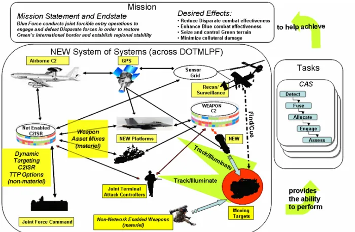
Elements ... 2-12 Figure 2-7 CADM Support for Architecture Products ... 2-19 Figure 3-1 Overview and Summary Information (AV-1) - Representative Format... 3-2 Figure 3-2 CADM Diagram for Overview and Summary Information (AV-1)... 3-5 Figure 3-3 Taxonomies Used in Products ... 3-19 Figure 3-4 CADM Diagram for Integrated Dictionary (AV-2) ... 3-21 Figure 4-1 DoD Electronic Commerce Concept of Operations (OV-1) ... 4-2 Figure 4-2 Joint Task Force Concept of Operations (OV-1) ... 4-3 Figure 4-3 Joint Network Enabled Weapon (NEW) Capability Operational Concept
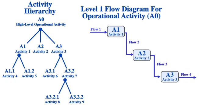
Graphic (OV-1)... 4-4 Figure 4-4 CADM Diagram for High-Level Operational Concept Graphic (OV-1) ... 4-6 Figure 4-5 Operational Node Connectivity Description (OV-2) Template... 4-12 Figure 4-6 Notional Example of an OV-2 Depicting Service Providers... 4-13 Figure 4-7 UML Operational Node Connectivity Description (OV-2) Template ... 4-13 Figure 4-8 CADM Diagram for Operational Node Connectivity Description (OV-2) ... 4-17 Figure 4-9 Operational Information Exchange Matrix (OV-3) – Template ... 4-25 Figure 4-10 CADM Diagram for Operational Information Exchange Matrix (OV-3) ... 4-28 Figure 4-11 Organizational Relationships Chart (OV-4) – Template... 4-35 Figure 4-12 UML OV-4 Sample... 4-35 Figure 4-13 CADM Diagram for Organizational Relationships Chart (OV-4) ... 4-37 Figure 4-14 Operational Activity Hierarchy Chart and Operational Activity Diagram
(OV-5) – Templates ... 4-42 Figure 4-15 Operational Activity Model (OV-5) – Template with Notional
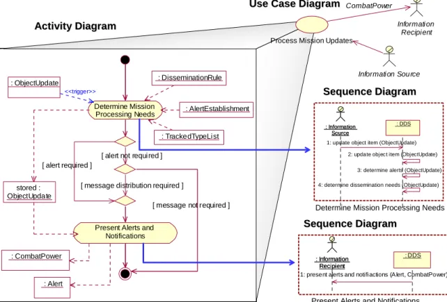
Annotations ... 4-43 Figure 4-16 UML Example OV-5 ... 4-44 Figure 4-17 CADM Diagram for Operational Activity Model (OV-5) ... 4-47
Figure 4-18 CADM Diagram for Operational Activity Sequences and Threads (OV-6).. 4-53 Figure 4-19 Operational Rules Model (OV-6a) – Action Assertion Example ... 4-55 Figure 4-20 CADM Diagram for Operational Rules Model (OV-6a) ... 4-58 Figure 4-21 Operational State Transition Description – High-Level Template ... 4-62 Figure 4-22 Anatomy of an Executable Operational Architecture ... 4-63 Figure 4-23 Sample Histograms Showing Results of a Simulation Run ... 4-64 Figure 4-24 CADM Diagram for Operational State Transition Description (OV-6b) ... 4-66 Figure 4-25 Operational Event-Trace Description (OV-6c) – UML-type Template ... 4-70 Figure 4-26 Operational Event-Trace Description (OV-6c) – IDEF3 Example... 4-71 Figure 4-27 UML Representation of an Operational Event-Trace (OV-6c) ... 4-71 Figure 4-28 CADM Diagram for Operational Event-Trace Description (OV-6c)... 4-74 Figure 4-29 Logical Data Model (OV-7) – Template... 4-77 Figure 4-30 UML Class Diagram for Logical Data Model (OV-7) – Template ... 4-78 Figure 4-31 CADM Diagram for Logical Data Model (OV-7) ... 4-79 Figure 5-1 SV-1 Internodal Template Showing Systems... 5-3 Figure 5-2 SV-1 Internodal Version – Node Edge to Node Edge Showing System
Functions ... 5-3 Figure 5-3 SV-1 Internodal Version Showing System-System Interfaces – Template ... 5-4 Figure 5-4 SV-1 Intranodal Version – Template ... 5-4 Figure 5-5 SV-1 Intrasystem Version – Example Showing a KI, a Database, and Other
Software and Hardware Items ... 5-5 Figure 5-6 UML Node/Component Diagram for SV-1 Internodal Version Showing
Systems – Template ... 5-6 Figure 5-7 UML Node/Component Diagram for SV-1 Internodal Version Showing
System-System Interfaces – Template ... 5-6 Figure 5-8 Notional Example: Services Interface Description (SV-1): Layer 1 Example... 5-9 Figure 5-9 Notional Example: Services Interface Description (SV-1): Layer 2 Example. 5-10 Figure 5-10 CADM Diagram for Systems and Services Interface Description (SV-1)... 5-12 Figure 5-11 Systems Communications Description, Internodal Version (SV-2) –
Template... 5-17 Figure 5-12 Systems Communications Description, Intranodal Version (SV-2) –
Template... 5-17 Figure 5-13 UML Representation for SV-2 ... 5-18 Figure 5-14 Notional Example: Services Interface Description (SV-2): Layer 2
Figure 5-15 CADM Diagram for Systems and Services Communications Description
(SV-2) ... 5-22 Figure 5-16 Systems-Systems Matrix (SV-3) – Template... 5-24 Figure 5-17 CADM Diagram for Systems-Systems, Systems, and
Services-Services Matrix (SV-3) ... 5-26 Figure 5-18 Systems Functionality Description (SV-4a) – Template (Functional
Decomposition) ... 5-29 Figure 5-19 Systems Functionality Description (SV-4a) – Template (Data Flow
Diagram)... 5-29 Figure 5-20 UML Use Case Diagram for Systems Functionality Description (SV-4) ... 5-30 Figure 5-21 UML Class Diagram for Systems Functionality Description (SV-4a)... 5-31 Figure 5-22 Sequence Diagram... 5-31 Figure 5-23 Notional Example: Service Functionality Description (SV-4b): Functional
Decomposition... 5-34 Figure 5-24 Notional Example: Service Functionality Description (SV-4b): Data Flow
Diagram ... 5-35 Figure 5-25 CADM Diagram for Systems and Services Functionality Description
(SV-4)... 5-36 Figure 5-26 Operational Activity to Systems Function Traceability Matrix (SV-5a) ... 5-40 Figure 5-27 Capability to System Traceability Matrix (SV-5b) ... 5-41 Figure 5-28 Notional Example: Operational Activity to Services Traceability Matrix
(SV-5c) ... 5-43 Figure 5-29 CADM Diagram for Operational Activity to Systems Function and
Services Traceability Matrices (SV-5) ... 5-45 Figure 5-30 Systems Data Exchange Matrix (SV-6) – Template... 5-48 Figure 5-31 UML Logical Service Realization Diagram (SV-6) ... 5-49 Figure 5-32 CADM Diagram for Systems and Services Data Exchange Matrix (SV-6) ... 5-52 Figure 5-33 Systems Performance Parameters Matrix (SV-7) – Notional Example ... 5-55 Figure 5-34 CADM Diagram for Technology Systems and Services Performance
Parameters Matrix (SV-7) ... 5-58 Figure 5-35 Systems Evolution Description (SV-8) – Migration ... 5-60 Figure 5-36 Systems Evolution Description (SV-8) – Evolution... 5-61 Figure 5-37 CADM Diagram for Systems and Services Evolution Description (SV-8) .... 5-62 Figure 5-38 CADM Diagram for Systems Technology Forecast (SV-9)... 5-67 Figure 5-39 CADM Diagram for Systems and Services Functionality Sequence and
Figure 5-40 Rules Model (SV-10a) – Action Assertion Example... 5-72 Figure 5-41 CADM Diagram for Systems and Services Rules Model (SV-10a) ... 5-75 Figure 5-42 Systems State Transition Description (SV-10b) – High-Level Template ... 5-77 Figure 5-43 CADM Diagram for Systems and Services State Transition Description
(SV-10b)... 5-79 Figure 5-44 Systems Event-Trace Description (SV-10c) – Template... 5-81 Figure 5-45 Notional Example: Services Event-Trace Description (SV-10c)... 5-83 Figure 5-46 CADM Diagram for Systems and Services Event-Trace Description
(SV-10c) ... 5-84 Figure 5-47 Schema (SV-11) – Representation Options... 5-87 Figure 5-48 UML Class Diagram for Physical Schema (SV-11)... 5-88 Figure 5-49 CADM Diagram for Physical Schema (SV-11)... 5-90 Figure 6-1 Systems Products Associated with Standards ... 6-3 Figure 6-2 CADM Diagram for Joint Technical Architecture ... 6-7 Figure 6-3 CADM Diagram for Technical Standards Forecast (TV-2)... 6-11 Figure 7-1 Major Product Relationships ... 7-3 Figure 7-2 Operational View Product Relationships... 7-4 Figure 7-3 Systems View Product Relationships... 7-5 Figure 7-4 Detail of Systems Elements that are Associated with Standards ... 7-6
LIST OF TABLES
TABLE PAGE
Table 1-1 Organization of Volume II ... 1-2 Table 2-1 List of Products ... 2-3 Table 2-2 Data Element Definitions for Common Data Structures ... 2-20 Table 3-1 Data Element Definitions for Overview and Summary Information (AV-1)... 3-6 Table 3-2 Data Element Definitions for Integrated Dictionary (AV-2) ... 3-23 Table 4-1 Data Element Definitions for High-Level Operational Concept Graphic
(OV-1)... 4-7 Table 4-2 Data Element Definitions for Operational Node Connectivity Description
(OV-2)... 4-18 Table 4-3 Data Element Definitions for Operational Information Exchange Matrix
(OV-3)... 4-32 Table 4-4 Data Element Definitions for Organizational Relationships Chart (OV-4) ... 4-38 Table 4-5 Data Element Definitions for Operational Activity Model (OV-5) ... 4-49 Table 4-6 Data Element Definitions for Operational Rules Model (OV-6a) ... 4-59 Table 4-7 Data Element Definitions for Operational State Transition Description
(OV-6b) ... 4-67 Table 4-8 Data Element Definitions for Logical Data Model (OV-7) ... 4-80 Table 5-1 Data Element Definitions for Systems and Services Interface Description
(SV-1) ... 5-13 Table 5-2 Data Element Definitions for Systems and Services Communications
Description (SV-2)... 5-23 Table 5-3 Data Element Definitions for Systems-Systems, Services-Systems, and
Services-Services Matrices (SV-3) ... 5-27 Table 5-4 Data Element Definitions for Systems and Services Data Exchange Matrix
(SV-6) ... 5-53 Table 5-5 Data Element Definitions for Systems and Services Performance Matrix
(SV-7) ... 5-59 Table 5-6 Data Element Definitions for Systems and Services Evolution Description
(SV-8) ... 5-63 Table 5-7 Systems Technology Forecast (SV-9) – Notional Example ... 5-65 Table 5-8 Systems Technology Forecast (SV-9) – Template... 5-65 Table 5-9 Data Element Definitions for Systems Technology Forecast (SV-9)... 5-68 Table 5-10 Data Element Definitions for Physical Schema (SV-11)... 5-91
Table 6-1 Technical Standards Profile (TV-1) Template... 6-2 Table 6-2 TV-1 Template with Corresponding System Elements ... 6-4 Table 6-3 TV-1 Template for Systems with Corresponding Time Periods ... 6-5 Table 6-4 Data Element Definitions for Technical Standards Profile (TV-1) ... 6-8 Table 7-1 Detailed Architecture Data Element Relationships... 7-7
EXECUTIVE SUMMARY
Architectures within the Department of Defense (DoD) are created for a number of reasons. From a compliance perspective, the DoD is compelled by law and policy (i.e., Clinger-Cohen Act, Office of Management and Budget (OMB) Circular A-130) to develop architectures. From a practical perspective, experience has demonstrated that the management of large organizations employing sophisticated systems and technologies in pursuit of joint missions demands a structured, repeatable method for evaluating investments and investment alternatives, implementing organizational change, creating new systems, and deploying new technologies. Towards this end, the DoD Architecture Framework (DoDAF) was established as a guide for the development of architectures.
The DoDAF provides the guidance and rules for developing, representing, and understanding architectures based on a common denominator across DoD, Joint, and multinational boundaries. It provides external stakeholders with insight into how the DoD develops architectures. The DoDAF ensures that architecture descriptions can be compared and related across programs, mission areas, and ultimately, the enterprise, thus, establishing the foundation for analyses that supports decision-making processes throughout the DoD.
As the Department takes appropriate strides to ensure advancement of the Information Technology (IT) environment, it becomes essential for the DoDAF to transform to sufficiently support new technologies. A significant evolution occurring today is the Department’s transformation to a new type of information intensive warfare known as Net-Centric Warfare (NCW). NCW focuses on generating combat power from the effective linking or networking of the warfighting enterprise, and making essential information available to authenticated, authorized users when and where they need it. This ability is at the heart of net-centricity and essential to achieving Net-Centric Operations (NCO).
DoDAF v1.5 is a transitional version that responds to the DoD’s migration towards NCW. It applies essential net-centric concepts1 in transforming the DoDAF and acknowledges that the advances in enabling technologies – such as services within a Service Oriented Architecture (SOA) – are fundamental to realizing the Department’s Net-Centric Vision2. DoDAF v1.5 addresses the immediate net-centric architecture development needs of the Department while maintaining backward compatibility with DoDAF v1.0.
In addition to net-centric guidance, DoDAF v1.5 places more emphasis on architecture data, rather than the products, introduces the concept of federated architectures, and incorporates the Core Architecture Data Model (CADM) as an integral component of the DoDAF. These aspects
1 Reference DoDAF v1.5 Volume II for further information on the following net-centric concepts and their application to DoDAF: 1) Populate the Net-Centric Environment , 2) Utilize the Net-Centric Environment , 3) Accommodate the Unanticipated User, 4) Promote the Use of Communities Of Interest (COI), 5) Support Shared Infrastructure
2 2005 National Defense Strategy
Architecture: the structure of components, their relationships, and the principles and guidelines governing their design and evolution over time.
DoD Integrated Architecture Panel, 1995, based on IEEE STD 610.12
prepare the way for more efficient and flexible use and reuse of architecture data, enabling broader utility for decision makers and process3 owners.
The DoDAF is a three-volume set that inclusively covers the concept of the architecture framework, development of architecture descriptions, and management of architecture data.
• Volume I introduces the DoDAF framework and addresses the development, use, governance, and maintenance of architecture data.
• Volume II outlines the essential aspects of architecture development and applies the net-centric concepts to the DoDAF products.
• Volume III introduces the architecture data management strategy and
describes the pre-release CADM v1.5, which includes the data elements and business rules for the relationships that enable consistent data representation across architectures.
An Online Journal, hosted on the DoD Architecture Registry System (DARS) website (https://dars1.army.mil), replaces the DoDAF v1.0 Desk Book and is designed to capture development best practices, architecture analytical techniques, and showcase exemplar architectures.
The DoDAF will continue to evolve to meet the growing needs of decision makers in the Net-Centric Environment (NCE). Going forward, architectures will need to capture the development of a new generation of net-centric capabilities stemming from operational insights gained in Afghanistan and Iraq. As the maturation of the Global Information Grid (GIG) continues through GIG Capability Increments (an incremental time frame approach to the delivery of GIG-enabling capabilities), architectures will be a factor in evaluating increment investments, development, and performance at the mission portfolio levels. As the DoD increases its use of architecture data for decision-making processes, architects will need to understand how to aggregate the data for presentation purposes at the enterprise level. The DoDAF plays a critical role in the development of architectures and will continue to improve its support for the increasing uses of architecture data.
3CJCS Instruction 3170.01E, Joint Capabilities Integration and Development System (JCIDS); DoD Directive 7045.14, Planning, Programming, Budgeting, and Execution (PPBE); DoD Directive 5000.1, The Defense Acquisition System (DAS); DoD Directive 8115.01, Information Technology Portfolio Management (PfM)
1
INTRODUCTION
1.1 VOLUME II PURPOSE AND INTENDED AUDIENCE
The purpose of the DoDAF v1.5 Volume II is to define, provide a purpose for, and describe in detail each Framework product. This volume is organized with various readers in mind.
For the manager who needs to lead architecture development projects and who may need to use an architecture to make acquisition, budgeting, or resourcing decisions, product definition and product purpose subsections are provided in each product section to:
- Help these managers understand the architecture components or products. - Provide an appreciation of the potential level of effort involved in developing
architectures.
- Assist in discerning the potential uses of an architecture.
For the architect and engineering team who need to develop architecture products for high-level decision makers for use in decision support analysis, a detailed product description and an architecture data element table subsection are provided in each product section to:
- Enable the architect and his team to identify products to be included in the architecture based on the architecture’s intended use (see Figure 2-2, Architecture Products by Use).
- Determine architecture data needs. - Identify sources for the architecture data.
- Analyze and relate the architecture data gathered.
- Compose the architecture data into architecture products.
A Net-Centric Guidance subsection is provided in each product section. With the same architectural vision, the program manager, Component-level CIOs, and chief architects who are guiding the development of architectures, which include net-centric components, should view the Net-Centric Guidance subsections with their individual perspectives and duties to:
- Assist in developing architecture products that show how programs and
Component organizations are:
• Using and consuming information and capabilities from the NCE
• Facilitating widespread use of information and capabilities beyond their initial predefined set of users
• Utilizing collaborative communities to make information and
capabilities more understandable in the NCE • Providing and consuming shared infrastructure
- Aid in developing net-centric architectures compliant with the Net-Centric
Operations and Warfare Reference Model (NCOW RM)
- Support program level architecture reviews in support of the Warfighter,
Business, Intelligence, and Enterprise Information Environment Mission Areas portfolios
Section Content
Section 1 Introduction – Identifies the purpose and intended audience of Volume II. Provides a brief overview of DoDAF terms.
Section 2
Architecture Basics – Views, Products, and Architecture Data – Provides an overview of basic concepts of the DoD architecture approach and introduces the net-centric concepts.
Section 3 All-Views Products – Provides All-View product descriptions. Section 4 Operational View Products – Provides Operational View product descriptions. Section 5 Systems and Services View Products – Provides Systems and Services View product descriptions. Section 6 Technical Standards View Products – Provides Technical Standards View product descriptions. Section 7 Framework Architecture Data Element Relationships – Contains details of the architecture data element and product relationships.
Table 1-1 Organization of Volume II
The product definitions are provided according to the format described below. 1.1.1 Product Description Structure
Products for each view are presented individually, with the following separate subsections: 1. A product overview (what is it)
2. A brief statement on the purpose of the product (why is it useful) 3. A detailed description that includes:
- Narrative details about the product and its representation in Structured Analysis (SA) and in Object-Oriented (OO) notation, where applicable
- One or more generic templates and/or examples (For most of the products, one or more generic templates are shown to illustrate the basic format of the product; when a generic template is not appropriate, one or more examples are shown.) 4. Net-centric guidance that includes:
- An updated purpose of the view in a NCE
- Detailed guidance for tailoring the product to the net-centric concepts - Example net-centric product diagrams, as applicable
5. CADM information space and model, and as applicable, data element and
relationship table
1.2 OVERVIEW
The DoDAF v1.5 defines a common approach for DoD architecture description development, presentation, and integration. The DoDAF v1.5 is a net-centric update to the framework which provides a common approach to DoD net-centric architecture development and includes
guidance to programs, managers, and architects who are developing systems that operate in the NCE as mandated by DoD CIO policies, guidance, and instruction. The net-centric update of DoDAF v1.5 leverages the previous DoDAF v1.0 to describe three types of architectures: Traditional, Net-Centric, and Hybrid (a mix of traditional and net-centric).
An architecture description is a representation of a defined domain, as of a current or future point in time, in terms of its component parts, how those parts function, the rules and constraints under which those parts function, and how those parts relate to each other and to the environment. Within the DoDAF, architectures are described in terms of four views: Operational View (OV), Systems and Services View (SV), Technical Standards View (TV), and All-View (AV). An architecture description is composed of architecture products that are interrelated within each view and are interrelated across views. Architecture products are those graphical, textual, and tabular items that are developed in the course of:
• Gathering architecture data
• Identifying their composition into related architecture components or composites
• Modeling the relationships among those composites
Underlying the products is the CADM, which defines a standard set of architecture data entities and relationships for architecture data.
The term architecture is generally used both to refer to an architecture description and an architecture implementation. An architecture description is a representation of a current or postulated real-world configuration of resources, rules, and relationships. Once the representation enters the design, development, and acquisition portion of the system development life-cycle process, the architecture description is then transformed into a real implementation of capabilities and assets in the field. The Framework itself does not address this representation-to-implementation transformation process but references policies that are relevant to that process.
Hereafter in this document, the term architecture will be used as a shortened reference to architecture description. Occasionally, the term architecture description is used for emphasis.
2
ARCHITECTURE BASICS - VIEWS, PRODUCTS, AND
ARCHITECTURE DATA
2.1 ARCHITECTURE VIEWS
As defined in Volume I, the term integrated architecture refers to one in which architecture data elements are uniquely identified and consistently used across all products and views within the architecture. In most cases, an integrated architecture description has an OV, SV, TV, and an All View (AV) that are integrated with each other (i.e., there are common points of reference linking the OV and SV and also linking the SV and TV). The Operational Activity to Systems Functionality Traceability Matrix (SV-5), for example, relates operational activities from the Operational Activity Model (OV-5) to system functions from the Systems Functionality Description (SV-4); the SV-4 system functions are related to systems in the Systems Interface Description (SV-1), thus bridging the OV and SV. An architecture is defined to be an integrated architecture when products and their constituent architecture data elements are developed, such that architecture data elements defined in one view are the same (i.e., same names, definitions, and values) as architecture data elements referenced in another view.
Figure 2-1 illustrates the major relationships.
Operational View
Identifies What Needs to be Accomplished and Who Does It
• Specific System Capabilities Required to Satisfy Information Exchanges
• Technical Standards Criteria Governing Interoperable Implementation/Procurement of the Selected System Capabilities
•W hat N eeds to B e D one •W ho D oes It •In form atio n E xcha nges Req uire d to Get It D one •S yste ms and Ser vice s that Sup port the Act iviti es a nd Info rmat ion Exc hang es
Systems and Services View
Relates Systems, Services, and Characteristics to
Operational Needs
Technical Standards View
Prescribes Standards and Conventions All-View
Describes the Scope and Context (Vocabulary) of the Architecture
Figure 2-1: Fundamental Linkages Among the Views
2.1.1 Definition of the Operational View
The OV captures the operational nodes, the tasks or activities performed, and the information that must be exchanged to accomplish DoD missions. It conveys the types of information exchanged, the frequency of exchange, which tasks and activities are supported by the information exchanges, and the nature of information exchanges.
2.1.2 Definition of the Systems View
The SV captures system, service, and interconnection functionality providing for, or supporting, operational activities. DoD processes include warfighting, business, intelligence, and infrastructure functions. The SV system functions and services resources, and components may be linked to the architecture artifacts in the OV. These system functions and service resources
support the operational activities, and facilitate the exchange of information among operational nodes.
2.1.3 Definition of the Technical Standards View
The TV is the minimal set of rules governing the arrangement, interaction, and interdependence of system parts or elements. Its purpose is to ensure that a system satisfies a specified set of operational requirements. The TV provides the technical systems implementation guidelines upon which engineering specifications are based, common building blocks are established, and product lines are developed. It includes a collection of the technical standards, implementation conventions, standards options, rules, and criteria that can be organized into profile(s) that govern systems and system or service elements for a given architecture.
2.1.4 Definition of the All-Views
There are some overarching aspects of an architecture that relate to all three views. These overarching aspects are captured in the AV products. The AV products provide information pertinent to the entire architecture but do not represent a distinct view of the architecture. AV products set the scope and context of the architecture. The scope includes the subject area and time frame for the architecture. The setting in which the architecture exists comprises the interrelated conditions that compose the context for the architecture. These conditions include doctrine; tactics, techniques, and procedures (TTP); relevant goals and vision statements; concepts of operations (CONOPS); scenarios; and environmental conditions.
2.2 ARCHITECTURE PRODUCTS
Architecture products that describe characteristics pertinent to the architecture purpose are those graphical, textual, and tabular items that are developed in the course of:
• Gathering architecture data
• Identifying their composition into related architecture components or composites
• Modeling the relationships among those composites
Choosing which products to develop for a given architecture description depends on the architecture’s intended use.
Table 2-1 lists products. The first column indicates the view applicable to each product. The second column provides an alphanumeric reference identifier for each product. The third column gives the formal name of the product. The fourth column indicates if the product’s definition and purpose were augmented to incorporate net-centric concepts. The fifth column captures the general nature of the product’s content. The sequence of products in the table does not imply a sequence for developing the products.
Additional products may be developed for a given architecture description depending on the intended use of the architecture (see Figure 2-2). Figure 2-2 identifies several categories for architecture usage and the product data that provide pertinent input to that use. The listed items are not meant to be exhaustive or all inclusive, but are illustrated to provide a starting point for determining the architecture data needed to address a particular area. The architecture data appropriate for any individual use case are highly dependent on the specific situation, objectives, and scope of the effect. Therefore, architects should consider the guidelines provided in the use matrix but make decisions based on the specifics of their particular architecture and its intended use.
Table 2-1: List of Products Applicable
View
Framework
Product Framework Product Name
Net-Centric
Extension General Description
All View AV-1 Overview and Summary Information
3
Scope, purpose, intended users, environment depicted, analytical findingsAll View AV-2 Integrated Dictionary
3
Architecture data repository with definitions of all terms used in all productsOperational OV-1 High-Level Operational Concept Graphic
3
High-level graphical/textual description of operational conceptOperational OV-2 Operational Node Connectivity
Description
3
Operational nodes, connectivity, and information exchange need lines between nodes
Operational OV-3 Operational Information Exchange Matrix
3
Information exchanged between nodes and the relevant attributes of that exchangeOperational OV-4 Organizational Relationships Chart
3
Organizational, role, or other relationships among organizationsOperational OV-5 Operational Activity Model
3
Capabilities, operational activities, relationships among activities, inputs, and outputs; overlays can show cost, performing nodes, or other pertinent information
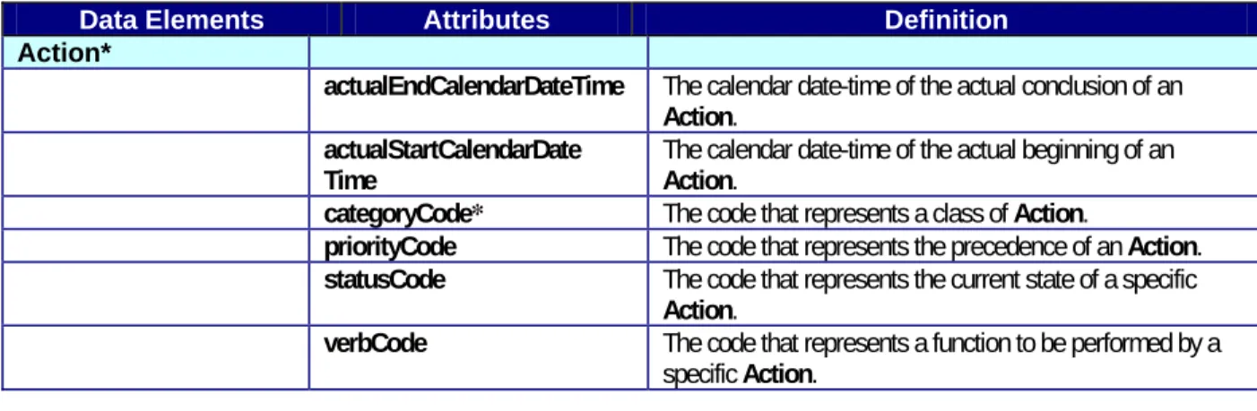
Operational OV-6a Operational Rules Model
3
One of three products used to describe operational activity—identifies business rules that constrain operation
Operational OV-6b Operational State Transition Description
3
One of three products used to describe operational activity—identifies business process responses to events
Operational OV-6c Operational Event-Trace Description
3
One of three products used to describe operational activity—traces actions in a scenario or sequence of events
Operational OV-7 Logical Data Model
3
Documentation of the system data requirements and structural business process rules of the Operational View
Systems and Services
SV-1 Systems Interface Description
Services Interface Description
3
Identification of systems nodes, systems, system items, services, and service items and their interconnections, within and between nodes
Systems and Services
SV-2 Systems Communications Description
Services Communications Description
3
Systems nodes, systems, system items, services, and service items and their related communications lay-downs Systems and Services SV-3 Systems-Systems Matrix Services-Systems Matrix Services-Services Matrix
3
Relationships among systems and services in a given architecture; can be designed to show relationships of interest, e.g., system-type interfaces, planned vs. existing interfaces, etc.
Systems and Services
SV-4a Systems Functionality Description Functions performed by systems and the system data flows among system functions
Systems and Services
SV-4b Services Functionality Description
3
Functions performed by services and the service data flow among service functionsSystems and Services
SV-5a Operational Activity to Systems Function Traceability Matrix Mapping of system functions back to operational activities Systems
and Services
SV-5b Operational Activity to Systems
Traceability Matrix
Mapping of systems back to capabilities or operational activities
Systems and Services
SV-5c Operational Activity to Services Traceability Matrix
3
Mapping of services back to operational activitiesSystems and Services
SV-6 Systems Data Exchange Matrix
Services Data Exchange Matrix
3
Provides details of system or service data elements being exchanged between systems or services and the attributes of that exchange
Applicable View
Framework
Product Framework Product Name
Net-Centric
Extension General Description Systems
and Services
SV-7 Systems Performance Parameters Matrix
Services Performance Parameters Matrix
3
Performance characteristics of Systems and Services View elements for the appropriate time frame(s)
Systems and Services
SV-8 Systems Evolution Description
Services Evolution Description
3
Planned incremental steps toward migrating a suite of systems or services to a more efficient suite, or toward evolving a current system to a future implementation
Systems and Services
SV-9 Systems Technology Forecast
Services Technology Forecast
3
Emerging technologies and software/hardware products that are expected to be available in a given set of time frames and that will affect future development of the architecture
Systems and Services
SV-10a Systems Rules Model
Services Rules Model
3
One of three products used to describe system and service functionality—identifies constraints that are imposed on systems/services functionality due to some aspect of systems design or implementation
Systems and Services
SV-10b Systems State Transition Description
Services State Transition Description
3
One of three products used to describe system and service functionality—identifies responses of a system/service to events
Systems and Services
SV-10c Systems Event-Trace Description
Services Event-Trace Description
3
One of three products used to describe system or service functionality—identifies system/service-specific refinements of critical sequences of events described in the Operational View
Systems and Services
SV-11 Physical Schema
3
Physical implementation of the Logical Data Model entities, e.g., message formats, file structures, physical schema
Technical
Standards TV-1 Technical Standards Profile
3
Listing of standards that apply to Systems and Services View elements in a given architecture
Technical
Standards TV-2 Technical Standards Forecast
Description of emerging standards and potential impact on current Systems and Services View elements, within a set of time frames
The following legend is used in Figure 2-2:
• A solid black circle (z) indicates the data are highly applicable to the indicated use (i.e., the data should be developed when the architecture is intended to support the indicated use).
• A white circle with a center black dot () indicates the data are often or partially applicable to the indicated use (i.e., the data should be developed when the architecture is intended to support the indicated use).
• A blank cell indicates that the data are usually not applicable (i.e., there is usually no need to develop the designated data when the architecture is intended to support the indicated use).
The list of uses is not exhaustive; instead, it is intended to provide initial insight into the use of the various architecture product data in supporting DoD processes. Future versions of the Framework are expected to expand the uses described.
Uses of Architecture Data 1 2 1 2 3 4 5 6 7 1 2 3 4 5 6 7 8 9 10 11 1 2 Capabilities
- Gaps/Shortfalls z z z
- Mission Effects & Outcomes, Operational
Task Performance z z z z z z z z z z z
- Trade-Offs z z z z z z z z z z z z z z z z
- Functional Solutions z z z z z z z z z z z z z z z z
Operations
- Process Re-engineering z z z z z z
- Personnel & Organizational Design z z z z z z z z
- Doctrine Development/Validation z z z z z z z
- Operational Planning (CONOPS and TTPs) z z z z z z z z z
Systems/Services
- Communications z z z z z z
- Interoperability and Supportability z z z z z z z z z z z z
- Evolution/Dependencies z z z z z z z z z z
- Materiel Solutions Design & Development z z z z z z z z z z z z z z z
- Facilities Packaging z z z z z z z z z z
- Performance z z z z z
- Training z z z z z z z z z z
- Leadership Development z z z z z z z z
- Metadata (for federation) z
z = Data Highly Applicable
= Data is Often or Partially Applicable
= Data is Usually Not Applicable
Applicable Architecture Product Data All
View Operational View (OV) Systems and Services View (SV)
Tech Stds View
Socialization/Awareness/Discovery Analysis & Assessment
Uses of Architecture Data 1 2 1 2 3 4 5 6 7 1 2 3 4 5 6 7 8 9 10 11 1 2
Capabilities
- Gaps/Shortfalls z z z
- Mission Effects & Outcomes, Operational
Task Performance z z z z z z z z z z z
- Trade-Offs z z z z z z z z z z z z z z z z
- Functional Solutions z z z z z z z z z z z z z z z z
Operations
- Process Re-engineering z z z z z z
- Personnel & Organizational Design z z z z z z z z
- Doctrine Development/Validation z z z z z z z
- Operational Planning (CONOPS and TTPs) z z z z z z z z z
Systems/Services
- Communications z z z z z z
- Interoperability and Supportability z z z z z z z z z z z z
- Evolution/Dependencies z z z z z z z z z z
- Materiel Solutions Design & Development z z z z z z z z z z z z z z
Uses of Architecture Data 1 2 1 2 3 4 5 6 7 1 2 3 4 5 6 7 8 9 10 11 1 2
Capabilities
- Gaps/Shortfalls z z z
- Mission Effects & Outcomes, Operational
Task Performance z z z z z z z z z z z
- Trade-Offs z z z z z z z z z z z z z z z z
- Functional Solutions z z z z z z z z z z z z z z z z
Operations
- Process Re-engineering z z z z z z
- Personnel & Organizational Design z z z z z z z z
- Doctrine Development/Validation z z z z z z z
- Operational Planning (CONOPS and TTPs) z z z z z z z z z
Systems/Services
- Communications z z z z z z
- Interoperability and Supportability z z z z z z z z z z z z
- Evolution/Dependencies z z z z z z z z z z
- Materiel Solutions Design & Development z z z z z z z z z z z z z z z
- Facilities Packaging z z z z z z z z z z
- Performance z z z z z
- Training z z z z z z z z z z
- Leadership Development z z z z z z z z
- Metadata (for federation) z
z = Data Highly Applicable
= Data is Often or Partially Applicable
= Data is Usually Not Applicable
Applicable Architecture Product Data All
View Operational View (OV) Systems and Services View (SV)
Tech Stds View
Socialization/Awareness/Discovery Analysis & Assessment
z
- Facilities Packaging z z z z z z z z z z
- Performance z z z z z
- Training z z z z z z z z z z
- Leadership Development z z z z z z z z
- Metadata (for federation) z
z = Data Highly Applicable
= Data is Often or Partially Applicable
= Data is Usually Not Applicable
Applicable Architecture Product Data All
View Operational View (OV) Systems and Services View (SV)
Tech Stds View
Socialization/Awareness/Discovery Analysis & Assessment
2.3 ARCHITECTURE PRODUCT DEVELOPMENT
The Framework products portray the basic architecture data elements and relationships that constitute an architecture description. In Volume I of the Framework, a process is described for developing architecture descriptions. The six steps of the architecture development process consist of (1) Determine Intended Use of Architecture, (2) Determine Scope of Architecture, (3) Determine Data Required to Support Architecture Develoopment, (4) Collect, Organize, Correlate, and Store Architecture Data, (5) Conduct Analysis in Support of Architecture Objectives, and (6) Document Results in Accordance with Architecture Framework. These steps are independent of any methodology4 that might be used in designing the architecture, and require the involvement of the architect and the necessary stakeholders to determine these overarching architecture drivers.
2.3.1 Product Development Methodology Support
Step six of the architecture development process (described in Volume I) consists of building the requisite products. The Framework does not advocate the use of any one methodology (e.g., structured analysis vs. object orientation) or one notation over another (e.g., IDEF1X or Unified Modeling Language (UML) [2005] notation) to complete this step, but products should contain the required instances of architecture data elements and relationships (i.e., those marked with an asterisk [*] in the data element tables). However, the need for a well-defined and rigorous methodology is acknowledged. There are several candidate methodologies available for consideration, and the choice is ultimately governed by the nature of the architecture being defined, the expertise and preferences of the architecture team, the needs of the customer, and the architecture end users.
The actual gathering, analysis, and synthesis of information into an integrated architecture may be conducted using an integrated tool or set of tools that allow for the development of the products and accompanying text. The use of an integrated tool or tool suite is highly recommended for developing an integrated architecture for consistency and version control. The selected tool(s) should allow the architect to produce consistent products/views by performing cross-product checking. The selected tool(s) should include a mechanism for storing, updating, and retrieving architecture data and their relationships and an ability to automatically generate an integrated dictionary. The tool should be capable of importing/exporting from a CADM-conformant database.
Before selecting a specific architecture tool-set, the architecture team needs to determine the best method (i.e., object-oriented or structured analysis) to implement the purpose of the architecture. If the purpose of the architecture is to design a system largely for software development, then UML tools are likely the best choice. Alternately, if the purpose of the architecture is to analyze business processes, then IDEF tools are likely a good option. The architecture team must carefully select the best method, because there are no known automated tools to convert one method to another (i.e., IDEF to UML, UML to IDEF). IDEF favors process while UML favors objects. These considerations must also include the experience of the architecture staff, because extensive architecture training and mentoring is required for success
4 The Webster’s II New College Dictionary 2001, defines methodology as 1) the system of principles, procedures, and practices applied to a particular branch of knowledge and 2) the branch of logic dealing with the general principles of the formation of knowledge. While the Framework defines an approach for developing architecture descriptions, it does not specify a methodology for developing an architecture description.
regardless of the method. For example, an architect team well versed in IDEF is not likely to succeed in UML without experienced object-oriented leadership and vice versa. There are significant differences between the two methods.
Structured analysis typically creates a hierarchy employing a single abstraction mechanism. The structured analysis method employs IDEF (Figure 2-3), is process driven, and starts with a purpose and a viewpoint. This method identifies the overall function and iteratively divides functions into smaller functions, preserving inputs, outputs, controls, and mechanisms necessary to optimize processes. Also known as a functional decomposition approach, it focuses on cohesion within functions and coupling between functions leading to structured data.
The functional decomposition of the structured method describes the process without delineating system behavior and dictates system structure in the form of required functions. The method identifies inputs and outputs as related to the activities.
Top Level Diagram
Inputs
Outputs
Controls
Mechanisms
• Inputs, Outputs & Controls represent
data (flowing among activities)
• Mechanisms can be systems, people, or
nodes, etc.
• Leaf activities often become software
elements (dictating design, leaves user interaction for late discovery)
Top Level Diagram
Inputs
Outputs
Controls
Mechanisms
• Inputs, Outputs & Controls represent
data (flowing among activities)
• Mechanisms can be systems, people, or
nodes, etc.
• Leaf activities often become software
elements (dictating design, leaves user interaction for late discovery)
Figure 2-3: Example Structured Analysis
One reason for the popularity of structured analysis is its intuitive ability to communicate high-level processes and concepts, whether single system or enterprise levels. Discovering how objects might support functions for commercially prevalent object-oriented development is unclear.
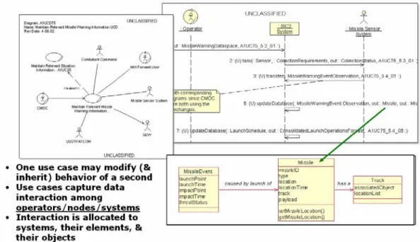
In contrast to IDEF, the UML is interface driven with multiple abstraction mechanisms useful in describing service-oriented architectures (SOAs). The object-oriented method (Figure 2-4) starts with the stakeholder and the operational activities required. The method identifies a use case (ways the user employs or makes use of the system) to generate important results – also known as results of value (ROV), thereby achieving warfighter desired effects. The method assigns required behavior (the way – machines or systems operate or interact) to the systems as described by the use case. The process iteratively allocates behavior to smaller system elements (products, services, classes, objects, etc.) while optimizing and identifying reuse opportunities.
The object-oriented method and associated UML tools5 provide object decomposition focused on operational objects and generalization (inheritance6). This practice creates a flexible interdependent web of elements with inherited properties and relationships. In addition, well-designed object-oriented tools provide an architecture environment where multiple architecture teams can share visionary process consistency and architectural artifacts, such as use cases and classes, while managing the evolution of the architecture over time.
Figure 2-4: Example Object-Oriented
The UML describes the system behavior at its surface from the user’s perspective by explicitly representing operator and inter-system dialog. The method organizes functionality along generalization-specialization lines, promoting process consistency and product line development. The ROV focused method (following similar principles described by Lean-Six Sigma) pays special attention to component interfaces and system behavior while leaving the design space open for designers, and keeps user behavioral needs foremost. This method lays the foundation for direct object-oriented development activities. In short, structured analysis emphasizes process and functions, while object-oriented analysis emphasizes system behavior using objects.
2.3.2 Architecture Products and Levels of Detail
Most graphical products (e.g., OV-2, OV-5, SV-1, and SV-4) permit the modeling of their respective architecture data elements using decomposition (i.e., several diagrams of the same product may be developed for the same architecture, where each diagram shows an increasing level of detail). An example of levels of detail are the various perspectives such as planner, owner, designer, or builder defined by Zachman [Zachman, 1987]. In general, the level of usable
5 It is important to note that not all UML tools employ effective object-oriented methods. The modeling language itself is not object-oriented, but provides the basis for well-written object-oriented tools. Some tools on the surface appear to be object-oriented due to their apparent UML construct, but employ structured analysis concepts.
6 Inheritance - a feature whereby a new object can be created from existing objects and, as a consequence of creation, possess the variables and methods of the parent object.