VMware vCloud
®
Architecture Toolkit
Architecting a VMware vCloud
Version 2.0.1 October 2011
© 2011 VMware, Inc. All rights reserved. This product is protected by U.S. and international copyright and intellectual property laws. This product is covered by one or more patents listed at
VMware is a registered trademark or trademark of VMware, Inc. in the United States and/or other jurisdictions. All other marks and names mentioned herein may be trademarks of their respective companies.
VMware, Inc 3401 Hillview Ave Palo Alto, CA 94304
Contents
1.
Overview
... 7
1.1 Audience ... 7
1.2 Scope... 7
1.3 Document Topics ... 8
2.
vCloud Architecture
... 9
2.1 System Architecture ... 9
2.2 vCloud Components ... 10
2.3 vCloud Infrastructure Logical Design ... 11
3.
Management Cluster
... 13
3.1 Component Sizing ... 14
3.2 Compute ... 15
3.3 Network ... 16
3.4 Storage ... 16
3.5 vCenter Linked Mode ... 16
3.6 Cell Load Balancing ... 17
4.
Resource Groups
... 18
4.1 Compute ... 18
4.2 Network ... 19
4.3 Storage ... 22
4.4 vCloud Resource Sizing ... 24
5.
vCloud Resource Design
... 28
5.1 vCloud Director Constructs ... 28
5.2 Organizations ... 30
5.3 Provider Virtual Datacenter ... 31
5.4 Organization Virtual Datacenters ... 33
5.5 vCloud Networking ... 39
5.6 Networking – Public vCloud Example ... 51
5.7 Networking – Private vCloud Example ... 54
6.
vCloud Metering
... 57
6.1 vCenter Chargeback ... 57
6.2 Maximums ... 59
6.3 Cost Calculation ... 60
7.
Orchestration and Extension
... 62
7.1 vCloud API ... 62
7.2 vCloud Messages ... 63
7.3 vCenter Orchestrator ... 64
7.4 vCenter Orchestrator Examples ... 70
8.
Multi-Site Considerations
... 72
9.
Hybrid vCloud Considerations
... 75
9.1 vCloud Connector Considerations ... 75
10.
References
... 78
Appendix A: Availability Considerations
... 79
vCloud Director Cell Load Balancing ... 82
Appendix B: Security
... 85
Network Access Security ... 85
DMZ Considerations ... 88
List of Figures
Figure 1. System Architecture ... 9
Figure 2. vCloud Components ... 11
Figure 3. vCloud Logical Architecture Overview ... 12
Figure 4. vCloud Management Cluster ... 13
Figure 5. Three-Host Management Cluster ... 15
Figure 6. vCloud Resource Groups ... 18
Figure 7. Auto Deploy First Boot ... 19
Figure 8. Physical, Virtual, and vCloud Abstraction Mapping ... 28
Figure 9. Extending Virtual Datacenters ... 32
Figure 10. Reservation Pool ... 33
Figure 11. Allocation Pool ... 34
Figure 12. Pay-As-You-Go ... 34
Figure 13. vApp Placement Algorithm ... 37
Figure 14. External Organization Network (Direct) ... 41
Figure 15. External Organization Network (Routed) ... 42
Figure 16. Internal Organization Network (Isolated) ... 42
Figure 17. vApp Network (Direct) –> Organization Network (Direct) ... 43
Figure 18. vApp Network (Direct) –> Organization Network (Routed) ... 44
Figure 19. vApp Network (Direct) –> Organization Network (Isolated) ... 44
Figure 20. vApp Network (Fenced) –> Organization Network (Direct) ... 45
Figure 21. vApp Network (Fenced) –> Organization Network (Routed) ... 45
Figure 22. vApp Network (Fenced) –> Organization Network (Isolated) ... 45
Figure 23. vApp Network (Routed) –> Organization Network (Direct) ... 46
Figure 24. vApp Network (Routed) –> Organization Network (Routed) ... 46
Figure 25. vApp Network (Routed) –> Organization Network (Isolated) ... 47
Figure 26. vApp Network (Isolated) ... 47
Figure 27. Organization Network Static Routing Use Case 1 ... 48
Figure 28. Organization Network Static Routing Use Case 2 ... 49
Figure 29. vApp Network Static Routing Use Case ... 50
Figure 30. Example of Public vCloud Networking ... 53
Figure 31. Example of Private vCloud Networking ... 54
Figure 34. vCenter Orchestrator Architecture ... 64
Figure 35. vCenter Orchestrator as a vCloud Director Extension ... 71
Figure 36. Two Sites with Local VCD Instances Managing Two Local vCenter Servers ... 72
Figure 37. Remote Console Flow ... 73
Figure 38. Two Sites with Isolated vCloud Director Instances ... 74
Figure 39. Hybrid vCloud Example ... 75
Figure 40. vCloud Connector Architecture ... 76
Figure 41. Site-to-Site VPN connectivity ... 87
Figure 42. vCloud Director Port Requirements Illustrated ... 90
List of Tables
Table 1. Document Topics ... 8Table 2. vCloud Components ... 10
Table 3. Component Requirements for a Management Cluster ... 14
Table 4. Definition of Resource Pool and Virtual Machine Split ... 24
Table 5. Memory, CPU, Storage, and Networking ... 25
Table 6. Example Consolidation Ratios ... 25
Table 7. vCloud Maximums ... 26
Table 8. vCloud Director Constructs... 29
Table 9. Linked Clone Deployment ... 35
Table 10. Public vCloud Virtual Datacenter Requirements ... 38
Table 11. Private vCloud Virtual Datacenter Requirements ... 39
Table 12. Network Pool Options ... 40
Table 13. Public vCloud Network Requirements ... 51
Table 14. Private vCloud Network Requirements ... 54
Table 15. vCloud Hierarchy Allocation Units ... 60
Table 16. Reference Documentation ... 78
Table 17. vCloud Availability Considerations ... 79
Table 18. Load Balancer Considerations ... 83
Table 19. Network Access Security Use Cases ... 85
Table 20. vCloud Director Port Requirements ... 89
1. Overview
Architecting a VMware vCloud provides guidance to architect an Infrastructure-as-a-Service (IaaS) cloud based on VMware vCloud®
This document, combined with the private or public service definition, can help you navigate through the applicable design considerations for architecting a vCloud solution. The documents,
Director™ (VCD). Simplifying the delivery of resources to end users requires the coordination of various infrastructure platforms. Both service providers and enterprises can use the guidelines in this document, with some variations depending on point of view.
Architecting a VMware vCloud, Operating a VMware vCloud, and Consuming a VMware vCloud
• Architecting a VMware vCloud provides best practices, design considerations, and design patterns for constructing a vCloud environment from its constituent components.
are designed to work together throughout the lifecycle of a VMware vCloud computing implementation with VMware
technologies.
• Operating a VMware vCloud includes best practices and considerations for operating and maintaining a vCloud environment. It covers the people, process, and technology involved in running a vCloud environment.
• Consuming a VMware vCloud covers the various considerations for the consumer when choosing to leverage vCloud computing resources.
This document is not a substitute for VMware product documentation, nor does it provide detailed implementation procedures for installing a vCloud.
1.1 Audience
This document is intended for, but not limited to, those involved in planning, designing, and implementing VMware vCloud solutions. The target audience is VMware Certified Professionals (VCP) familiar with VMware products, particularly VMware vSphere®
1.2 Scope
, VMware vCloud Director, VMware vShield Manager™ (VSM), and VMware vCenter Chargeback™. It is assumed that the reader has knowledge of and familiarity with vSphere concepts.
1.3 Document Topics
This document is structured into the sections shown in the following table.
Table 1. Document Topics
Section Description
Section 2, vCloud Architecture Introduces the core concepts of the vCloud solution stack.
Section 3, Management Cluster Describes the components required to stand up a vCloud.
Section 4, Resource Groups Provides guidance for configuring resources reserved for end-user workloads.
Section 5, vCloud Resource Design
Offers best practices for partitioning and delivering vCloud resources relative to customer requirements. Section 6, vCloud Metering Covers how to meter and charge for resources with
vCenter Chargeback. Section 7, Orchestration and
Extension
Walks through extending VCD automation via orchestration.
Section 8, Multi-Site Considerations
Covers multi-site considerations.
Section 9, Hybrid vCloud Considerations
Discusses extending VCD into the hybrid vCloud model.
Appendix A: Availability Covers design considerations for availability. Appendix B: Security Covers design considerations for security.
2. vCloud Architecture
VMware vCloud is a common set of cloud computing services for enterprises and service providers. Cloud computing is a style of computing that leverages the efficient pooling of on-demand, self-managed virtual infrastructure to provide resources consumable as a service.
This document focuses strictly on the IaaS layer, using vCloud Director to extend the capabilities of the vSphere virtualization platform.
2.1 System Architecture
VMware vCloud provides an open and modular architecture that offers choice and flexibility for running applications in public and private vCloud instances. vCloud Director implements the vCloud API, which provides compatibility and interoperability with other vCloud instances.
A cloud architecture is a strategic design that involves devising a conceptual framework that supports primary business requirements, deciding on the discrete functions of the system, organizing elements into distinct components, and defining boundaries and connections between interdependent components. Focus on clearly defining architecture goals and analyzing elements in a systematic and sufficient manner to facilitate design decisions that cut through the complexity found in today’s technology.
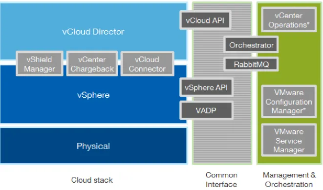
Figure 1 shows the fundamental structure and components of the cloud computing stack.
2.2 vCloud Components
Table 2 describes the components that comprise a VMware vCloud.
Table 2. vCloud Components
vCloud Component Description
VMware vCloud Director vCloud API
Layer of software that abstracts virtual resources and exposes vCloud components to consumers. Includes:
• vCloud Director Server (also referred to as a cell
• vCloud Director Database.
).
• VMware vCloud API, used to manage vCloud objects programmatically.
VMware vSphere Virtualization platform providing abstraction of physical infrastructure layer for vCloud. Includes:
• VMware ESXi™ hosts.
• VMware vCenter™ Server.
• vCenter Server database.
VMware vShield Provides perimeter network security for virtual datacenters using VMware vShield Edge™. Includes:
• vShield Manager.
• vShield Edge.
VMware vCenter Chargeback • Provides dynamic resource metering, cost modeling, and report generation. Includes:
• vCenter Chargeback Server.
• vCenter Chargeback database.
• Chargeback data collector.
• vCloud data collector.
• VSM data collector. VMware vCenter
Orchestrator™
VMware vCenter Orchestrator enables the automation of provisioning and operational tasks across VMware and third-party applications through an open and flexible plug-in architecture.
VMware vCloud Connector vSphere Client plug-in that allows users to connect to vSphere-based or vCloud Director-based clouds and manage them through a single interface.
Figure 2 shows the relationship of vCloud components.
Figure 2. vCloud Components
* Denotes current management products without vCloud Director integration.
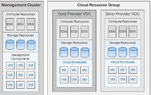
2.3 vCloud Infrastructure Logical Design
VMware recommends decoupling resources allocated for management functions from resources dedicated to user-requested workloads. Partition resources into:
• A management cluster containing core components and services needed to run the vCloud. This includes core vCloud components such as VMware vCenter Server, vCloud Director, and vCenter Chargeback Server.
• Resource groups represent dedicated resources for end-user consumption. Each resource group consists of VMware ESXi hosts managed by a vCenter Server, and is under the control of vCloud Director. vCloud Director can manage the resources of multiple resource groups.
Reasons for separating virtual resources along these lines are:
• To facilitate quicker troubleshooting and problem resolution. Management components are strictly contained in a relatively small and manageable cluster. Running management components on a large cluster with mixed environments can be time-consuming and make it difficult to track down and manage such workloads.
• Separation of management components from the resources they are managing. This helps avoid inadvertent changes to vCloud Director-created entities through the vSphere Client.
• Resources allocated for vCloud use have minimal overhead reserved. For example, vCloud resource groups would not host vCenter Server virtual machines. The exception is for vShield Edge devices that run on resource group hosts to facilitate traffic isolation.
• Enables consistent and transparent management of infrastructure resources, which is critical for scaling vCloud environments. Increases upgrade flexibility because management cluster upgrades are not tied to resource group upgrades.
• Prevent security attacks or intensive provisioning activity on the resource groups from affecting management component availability.
Figure 3. vCloud Logical Architecture Overview
Achieving economies of scale means scaling vCloud resources in a consistent and predictable manner. Follow applicable best practices when deploying the underlying vSphere infrastructure and other vCloud components.
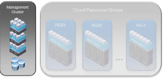
3. Management Cluster
The management cluster hosts all the necessary vCloud infrastructure components. Separating infrastructure components from resources used for end-user workloads improves manageability of the vCloud infrastructure.
Figure 4. vCloud Management Cluster
Management components include:
• vCenter Server or vCenter Server appliance.
• vCenter Server database.
• vCloud Director cells.
• vCloud Director database.
• vShield Manager (one per resource group vCenter Server.)
• vCenter Chargeback Server.
• vCenter Chargeback database.
• VMware vCenter™ Update Manager.
• vCenter Orchestrator.
Note
vShield Edge appliances are deployed automatically by vCloud Director through vShield Manager as needed and reside in the resource groups, not in the management cluster.Optional management cluster components include:
• VMware vCenter Server Heartbeat™.
• VMware Service Manager.
• VMware vCloud Connector.
• Databases for optional components.
• VMware vSphere Management Assistant.
• VMware vCenter Operations (currently not VCD-aware).
• VMware vCenter Configuration Manager (currently not VCD-aware).
Optional components are not required by the service definition
,
but are highly recommended to increase the operational efficiency of the solution.The management cluster may also include virtual machines or have access to servers that provide infrastructure services such as directory (LDAP), timekeeping (NTP), networking (DNS, DHCP), logging (syslog), and security. Review Section 4.4.1, Public vCloud Sizing Example, for detailed sizing
considerations.
Component databases, if running on the same platform, can be placed on the same database server if sized properly. For example, the databases used by vCloud Director, vCenter Server, and vCenter Chargeback can run on the same database server.
Both the management cluster and resource groups reside in the same physical site to provide a
consistent level of service. This minimizes latency issues, which could arise in a multi-site environment if workloads move between sites over a slower or less reliable network. See Section 8, Multi-Site
Considerations for considerations on connecting clouds residing in different sites.
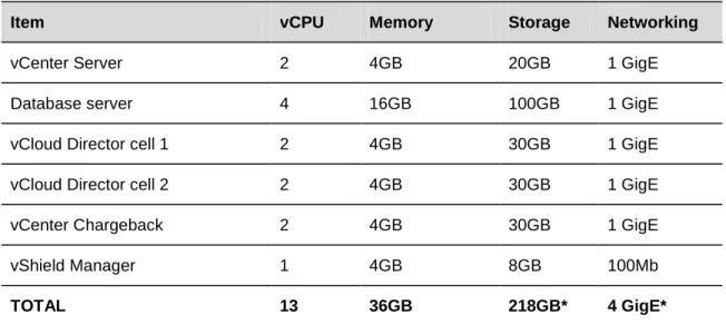
3.1 Component Sizing
Table 3 lists the requirements for each of the components that run in the management cluster. For the number of virtual machines and organizations listed in the private or public service definitions, you do not have to worry about scaling too far beyond the provided values.
Table 3. Component Requirements for a Management Cluster
Item vCPU Memory Storage Networking
vCenter Server 2 4GB 20GB 1 GigE
Database server 4 16GB 100GB 1 GigE
vCloud Director cell 1 2 4GB 30GB 1 GigE
vCloud Director cell 2 2 4GB 30GB 1 GigE
vCenter Chargeback 2 4GB 30GB 1 GigE
vShield Manager 1 4GB 8GB 100Mb
TOTAL 13 36GB 218GB* 4 GigE*
The database server hosts databases for vCenter Server, vCloud Director, and vCenter Chargeback Server. Use different users and instances for each database per VMware best practices. VMware vCloud Director 1.5 supports both Oracle and SQL Server databases.
In addition to the storage requirements in Table 3, a shared storage volume must be configured and made accessible to all cells in a vCloud Director server group to facilitate file transfers in a multicell environment. The size needed for this volume varies depending on the expected number of concurrent uploads. Once an upload completes, the vApp data moves to the designated organization virtual datacenter and the data no longer resides on the NFS volume. The recommended starting size for the NFS transfer volume is 250GB. Transferred images can be large, so monitor this volume and increase the size if necessary.
For additional installation prerequisites, see the vCloud Director Installation and Configuration Guide
3.2 Compute
The compute layer encompasses the CPU, memory, and hypervisor technology components. Follow vSphere best practices where possible when configuring and sizing compute resources.
Figure 5. Three-Host Management Cluster
A three-host cluster is used to support vCloud management components. Given advances in technology, three hosts are sufficient for typical vCloud environments. Add additional hosts if the management cluster becomes resource constrained. Enable vSphere High Availability (HA) and Distributed Resource
Scheduling (DRS) on the management cluster to provide availability for all management components. For vSphere HA, use percentage-based admission control policy in an “N+1” fashion instead of defining the amount of host failures a cluster can tolerate or specifying failover hosts. This allows management workloads to run evenly across the hosts in the cluster without the need to dedicate a host strictly for host failure situations. For higher availability, you can add an additional host for an N+2 cluster, although this is not a requirement of the vCloud private or public service definitions.
vCenter Server plays an integral role in end-user self-service provisioning by handling all virtual machine deployment requests from vCloud Director. VMware recommends increasing the availability of vCenter Server through solutions such as VMware vCenter Server Heartbeat.
vSphere Fault Tolerance can be used for continuous virtual machine protection only if all FT requirements are met. vCenter Site Recovery Manager™ (SRM) can be used to protect most components of the management cluster, but at this time, SRM cannot be used to protect vCloud Director cells because a secondary (DR) site is out of scope. Changes to IP addresses and schemas in recovered vCloud Director cells can result in complications.
vCloud Director 1.5 supports vSphere 4.0 U2 and later. Deploy vSphere 5.0 if possible to take advantage of the new features introduced in vCloud Director 1.5. When deciding on vSphere licensing, keep in mind that some functionality in vCloud Director requires specific features tied to particular vSphere editions. For example, automated deployment of vCloud networks requires the use of a distributed switch, a feature
3.3 Network
The network configuration for the management cluster includes, but is not limited to, the following best practices:
• Logical separation of network traffic for security and load considerations by type (management, virtual machine, VMware vSphere® vMotion®
• Network component and path redundancy.
, FT, IP storage.
• At least 10 GigE or GigE network speeds, if available.
• Use vSphere Distributed Switches (VDS) where possible for network management simplification. The architecture calls for the use of VDS in the resource group vCenter Servers, so it is a best practice to standardize on the VDS across all clusters, including the management cluster.
3.4 Storage
Use vSphere storage best practices where applicable for the management cluster. Examples include:
• Redundancy at the host (connector), switch, and storage array levels.
• All hosts in a cluster have access to the same datastores.
3.5 vCenter Linked Mode
vCenter linked mode provides a single pane-of-glass
vCloud Director maximums for powered on virtual machines and registered virtual machines are
substantially less than the vCenter linked mode maximums. Therefore, the number of linked mode objects in a vCloud environment will not approach linked mode maximums unless multiple vCloud instances are involved.
to allow a common administrative state to manage multiple vCenter instances. With linked mode configured, users can view and manage the inventories of all participating vCenter Server systems. Tasks invoked on a linked mode object are executed by the vCenter Server that manages the corresponding resource. Using linked mode in the vCloud Director context is useful because you can view all vCenter Servers that manage vCloud resources.
Additional considerations:
• The vCenter Server appliance does not support linked mode.
• A vCenter instance can only link with other vCenter instances that have the same version. This has upgrade implications when upgrading all vCenter Servers in a vCloud instance.
3.6 Cell Load Balancing
vCloud Director cells are stateless front-end processors for the vCloud. Each cell has a variety of purposes and self-manages various functions among cells while connecting to a central database. The cell manages connectivity to the vCloud and provides API and UI endpoints, or clients.
To improve availability and scale, implement a vCloud Director server group comprised of multiple vCloud Director cells. A multicell configuration requires load balancing or content switching of the front-end portal. Load balancers present a consistent address for services regardless of the underlying, responding node. They can spread session load across cells, monitor cell health, and add/remove cells from the active service pool. The cell architecture is not a true cluster since there is no failover from one cell to another. Any load balancer that supports SSL session persistence with network connectivity to the “public” facing Internet or internal service network can perform load balancing of vCloud Director cells. Refer to general best practices regarding performance, security, manageability, and so forth when deciding to share or dedicate load balancing resources.
Note
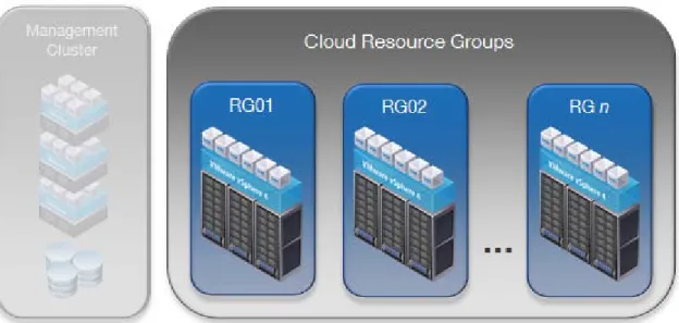
SSL offloading will not work with console proxy connections (VMRC). See Appendix A: Availability for additional load balancing considerations.4. Resource Groups
A resource groupFigure 6. vCloud Resource Groups
is a set of resources dedicated to end-user workloads and managed by a single vCenter Server. vCloud Director manages the resources of all attached resource group vCenter Servers. All provisioning tasks are initiated through vCloud Director and are passed down to the appropriate vCenter Server instance.
Provisioning resources in standardized groupings promotes a consistent approach for scaling vCloud environments. At a minimum, place all vCloud resource workloads in a separate cluster if you are using a single vCenter Server to manage both management components and vCloud resources.
Avoid making changes to resource group objects through the vSphere Client. Changing the state of vCloud Director-created objects may cause side effects and unpredictability because these objects are owned by vCloud Director.
4.1 Compute
Configure resource group ESXi hosts per vSphere best practices. Enable vSphere HA appropriately to protect against host and virtual machine failures.
The shift to Fault Domain Manager-based HA (FDM) in vSphere 5 is transparent to vCloud Director. The total number of hosts in an HA/DRS cluster remains 32, so cluster sizing guidance for vCloud
environments does not change. FDM requires a single master host, as opposed to legacy HA’s five primary nodes. If the master host fails, the remaining slave hosts participate in an election to choose a new master.
Do not exceed
Provider virtual datacenters represent a service offering. When building clusters, group similar servers together (number of hosts, number of cores, amount of memory, CPU type) to support differentiation of compute resources by capacity or performance.
4.1.1 Stateless ESXi
Stateless ESXi refers to running ESXi software on a host entirely in memory, with no local persistence data. Centralizing management of host state enables consistent configuration over large sets of similar hosts, as well as rapid provisioning of ESXi hosts. These aspects help improve operational efficiency in large-scale vCloud environments.
Stateless ESXi requires vSphere Auto Deploy, a deployment server that applies the image profile and host profile to the PXE-booted hosts. Install Auto Deploy on a standalone host or on the vCenter Server. The vCenter Server virtual appliance has Auto Deploy installed by default. Install vSphere PowerCLI in a location reachable by both vCenter and Auto Deploy. The host profile is essential to the stateless environment, as every reboot of a server clears the host of any local configuration data.
Configure all stateless ESXi hosts for DHCP. The DHCP server requires configuration changes to direct the ESXi host to a TFTP server. This can be a separate DHCP server or existing organization’s DHCP server. The vCenter Server virtual appliance includes DHCP and TFTP services.
Identify an image profile to use for vCloud hosts. This can be a profile stored in a public depot or a zipped file stored locally. If using host profiles, save a copy of the host profile to a location accessible by Auto Deploy and add rules to the rules engine using Image Builder PowerCLI.
Figure 7. Auto Deploy First Boot
vCloud Director can manage stateful or stateless hosts. If you choose the stateless option, add the vCloud Director vSphere Installation Bundle (VIB) (which contains the agent) to the image profile. (Currently, this is a manual process as there is no API call to register VIBs in an image profile.) The vCloud Director VIB is loaded automatically when the host boots up. For preparation and un-preparation of stateless hosts, vCloud Director configures the agent using a host profile with an associated answer file.
If the host is rebooted, the appropriate image profile is reloaded when the host starts back up. vCloud Director detects the state change, and the configuration is re-pushed to the host.
If using stateless mode, avoid creating designs that require host-specific configuration. When converting a prepared stateful host to stateless, unprepare hosts prior to the conversion.
4.2 Network
For the vCloud resource groups, configure networking with vSphere best practices in mind. In addition, increase the number of vSphere Distributed Switch ports per host from the default value to the maximum of 4096. This improves the scale at which vCloud Director can dynamically create port groups for vCloud networks. See the vSphere Administrator Guide for more information on increasing this value.
Increase the maximum transmission unit (MTU) size to 1600 for all devices residing in the transport network for vCloud Director network isolation. This includes physical network devices as well as the vSphere Distributed Switches. Failure to increase the MTU size causes packet fragmentation, negatively affecting network throughput performance of end-user workloads
4.2.1 I/O Controls
vCloud Director offers controls to guard against the misuse of resources by consumers. These include:
• Quotas for running and stored virtual machines determine how many virtual machines each user in the organization can store and power on in the organization's virtual datacenters. The quotas specified act as the default for all new users added to the organization.
• Limits for resource-intensive operations prevent these operations from affecting all users in an organization and provide defense against denial-of-service attacks.
• Simultaneous VMware Remote Console (VMRC) connections limits the number of simultaneous connections for performance or security reasons.
4.2.2 IPv6
Internet Protocol version 6 (IPv6) is the latest version of IP addressing, designed to succeed IPv4 as the standard protocol for the Internet. One of the key drivers for transitioning to IPv6 is that it supports a much larger address space of 264, as opposed to the 232
The vCloud Director components required to support IPv6 are: addresses for IPv4.
• Static IP pools.
• DHCP Server.
• Static IP assignments.
• NAT rules.
• Firewall rules.
vSphere infrastructure components supporting IPv6 include:
• vCenter Server.
• ESXi.
• vSwitches (standard and distributed).
• VMkernel.
• VMware vSphere® vMotion
• Virtual machines (guest customization available for Windows and Linux). ®.
vSphere virtual machines support IPv6 addressing and can be configured with:
• Static IPv6 address.
• Autoconfigure, using a prefix announcement from a router.
• DHCP, from a DHCP6 server.
Virtual machines managed by vCloud Director using IPv6 can only communicate to endpoints that are not behind vShield Edge devices. Currently, vShield Edge does not support IPv6. Virtual machines that communicate on the same directly attached vApp or organization network can use IPv6. To communicate with the outside world using IPv6, connect the organization’s virtual machines to a direct external
organization network.
Run virtual machines in dual stack IPv4 and IPv6. This is necessary because many destinations do not currently support IPv6.
If the underlying physical infrastructure does not support IPv6, another option is to establish a 6to4 tunnel using a router to provide connectivity into an IPv6 vCloud. Terminate the tunnel on a relay router that has a pure IPv6 interface as well as an IPv4 interface to move traffic between the two environments.
vCloud Director does not support IPv6 addressing for the cell network interfaces.
4.2.3 vShield Edge
VMware vShield Edge is a virtual firewall router that provides the perimeter security needed to support multi-tenancy. vShield Edge devices deploy automatically when routed or isolated organization or vApp networks are created from vCloud Director. For vApp networks, vShield Edge devices dynamically deploy and undeploy based on the power state of the vApp.
The license for vShield Edge included with vCloud Director (vShield for vCloud Director) does not include features such as VPN and load balancing capabilities, which are part of the fully licensed vShield Edge.
4.2.4 vShield App
VMware vShield App is a hypervisor-based, vNIC-level application firewall that controls and monitors all flows between virtual machines in a virtual datacenter. Firewall policies can be applied to vCenter containers or security groups, which are custom containers created through the vShield Manager user interface. Container policies enable the creation of mixed trust zone clusters without requiring an external physical firewall. vShield App also supports classic five tuple firewall rules.
Note
Currently, vCloud Director does not have integration with vShield App. Using vShield App in conjunction with vCloud Director is a supported configuration, but requires careful design of the vCloud infrastructure.4.2.5 vShield Endpoint
VMware vShield Endpoint offloads antivirus functions to a hardened security virtual machine delivered by partners such as Trend Micro. Endpoint uses EPSec APIs to peer into the file system to scan and remediate viruses. This removes the need for agents in the guest and prevents antivirus storms from consuming precious CPU cycles during scanning or AV update activities. Offloading antivirus provides enhanced security, as often the first task of malware is to disable AV agents. vShield Endpoint’s efficient AV architecture provides antivirus as a service for large-scale vCloud environments.
4.3 Storage
Designing storage resources for vCloud differs from traditional vSphere approach. Self-service provisioning shifts the responsibility of virtual machine storage placement from the provider to the consumer. Though this restricts the ability to optimize storage for applications, platforms improvements have emerged that assist in balancing workloads across storage resources. The goal shifts to
provisioning flexible pools of storage resources and maintaining consistent performance for end users. VMware recommends the following:
• Perform a current state analysis for storage usage and trends.
• Define the range of storage SLAs needed and appropriate pricing models.
• Create multiple tiers of storage based on SLAs, workloads, and cost.
• Map tiers to provider virtual datacenters in vCloud Director.
• Storage design provides optimal availability.
• Physical storage is modular and scalable.
• Monitor storage usage and trends using capacity analysis tools.
• Use storage performance tools to tune vApp storage workloads.
Currently, vCloud Director does not support tiering storage within a virtual datacenter, vApp, or virtual machine. If multiple types of storage resources are available, supply tiered pools of storage grouped by shared characteristics to provide differentiated service offerings. Configure shared storage in the resource groups per vSphere best practices.
Sizing considerations include:
• Datastore storage expectations
o What is the optimal size for datastores based on the physical storage and vCloud workload expectations?
o What is the average vApp size x number of vApps x spare capacity? For example: Average virtual machine size * # virtual machines * (1+ % headroom)
o What is the average virtual machine disk size?
o On average, how many virtual machines are in a vApp? o What is the expected number of virtual machines? o How much reserved spare capacity is needed for growth? o Will expected workloads be transient or static?
o Is Fast Provisioning utilized?
• Datastore performance characteristics
o Will expected workloads be disk intensive?
o What are the performance characteristics of the associated cluster? Note vCloud Director 1.5 does not support Raw Device Mappings (RDM).
4.3.1 Storage vMotion
Storage vMotion enables live migration of virtual machine disk files between and across shared storage locations. Relocating vApp disks is possible using the vCloud API or vSphere Client if the following conditions apply:
• The target datastore is part of the same organization virtual datacenter as the vApp.
• All virtual disks for an individual virtual machine are migrated to the same datastore.
• Use the vCloud API to initiate storage vMotion for linked clones to preserve the linked clone state.
Note
It is not recommended to invoke Storage vMotion migration of linked clones using the vSphere Client since this may cause undesirable effects such as the inflation of delta disks. If a storage vMotion of datastore and4.3.2 Storage I/O Control
host is attempted, the operation may fail.
Storage I/O Control (SIOC) manages storage resources across hosts through storage device latency monitoring and disk shares that are enforced at the datastore level. Preventing imbalances of storage resource allocation during times of contention protects virtual machine performance in highly
consolidated, virtualized environments.
Enabling SIOC on all datastores in a cluster ensures lower worst-case device latency by maintaining a balance between workload isolation/prioritization and storage I/O throughput. For more information, refer to the Storage I/O Control Technical Overview and Considerations for Deployment
SIOC does not support raw device mappings (RDM) or datastores with multiple extents. If you are using datastores backed by arrays with automated storage tiering, validate compatibility with SIOC.
4.3.3 vSphere Storage APIs – Array Integration
vSphere Storage APIs – Array Integration (formally VAAI) is a set of protocol interfaces between ESXi and storage arrays. These ESXi extensions enable storage-based hardware acceleration by allowing vSphere to pass storage primitives to supported arrays. VAAI improves storage task execution times, network traffic utilization, and CPU host utilization during heavy storage operations. In vSphere 5, new thin provisioning primitives enhance vSphere management of thin-provisioned block-based storage. In vSphere 5.0, array integration extensions are implemented as T10 SCSI-based commands. Devices that support the T10 SCSI standard do not require a VAAI plug-in to offload storage functions such as full copy, block zeroing, and locking. See the VMware Compatibility Guide
vCloud Director 1.5 supports block-based primitives (FC, iSCSI), but not the new NAS primitives introduced in vSphere 5.
4.3.4 Storage DRS
Storage DRS provides initial placement and on-going balancing recommendations for datastores in a Storage DRS-enabled datastore cluster
Currently datastore clusters cannot serve as a storage source to provider virtual datacenters. Do not enable Storage DRS for datastore clusters used with vCloud Director, as this is not a supported configuration.
. A datastore cluster represents an aggregation of datastore resources, analogous to clusters and hosts.
4.4 vCloud Resource Sizing
Resource sizing for a vCloud depends on the corresponding service definition. A private vCloud service definition may not specifically call out a required number of workloads to support. In that case, use the initial sizing for a public vCloud as guidance.
For a public vCloud, initial sizing for the vCloud consumer resources can be difficult to predict due to lack of data points on expected consumer uptake. The provider is also not aware of existing usage statistics for vCloud workloads.
The sizing examples in the next section come from the Service Definition for a Public VMware vCloud
Note
VMware recommends that you engage your local VMware representative for detailed sizing of your vCloud environment.and can assist with initial sizing of the vCloud environment.
4.4.1 Public vCloud Sizing Example
The service definition states that 50% of the virtual machines will use the Reservation Pool model and 50% will use the Pay-As-You-Go allocation model. The Reservation Pool model is applied to small, medium, and large pools with a respective split of 75%, 20%, and 5%. Therefore, small represents 37.5% of the total, medium represents 10% of the total, and large
Table 4
represents 2.5% of the total number of virtual machines in the environment.
lists the virtual machine count for the various virtual datacenters. The total virtual machine count of 1,500 reflects the specifications outlined in the Service Definition for a Public VMware vCloud
Table 4. Definition of Resource Pool and Virtual Machine Split
. Change this total to reflect your own target virtual machine count.
Type of Resource Pool Total Percentage Total Virtual Machines
Pay-As-You-Go 50% 750
Small Reservation Pool 37.5% 563*
Medium Reservation Pool 10% 150
Large Reservation Pool 2.5% 37*
TOTAL 100% 1,500
Note
Some total virtual machines values rounded up or down due to percentages. The Service Definition for a Public VMware vCloudTable 5
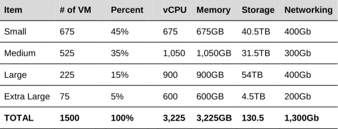
also calls out the distribution for virtual machines in the vCloud with 45% small, 35% medium, 15% large, and 5% extra large. shows the total amount of CPU, memory, storage, and networking needed.
Table 5. Memory, CPU, Storage, and Networking
Item # of VM Percent vCPU Memory Storage Networking
Small 675 45% 675 675GB 40.5TB 400Gb
Medium 525 35% 1,050 1,050GB 31.5TB 300Gb
Large 225 15% 900 900GB 54TB 400Gb
Extra Large 75 5% 600 600GB 4.5TB 200Gb
TOTAL 1500 100% 3,225 3,225GB 130.5 1,300Gb
Before determining your final sizing numbers, refer to VMware best practices for common consolidation ratios. Table 6 shows what the final numbers might look like using typical consolidation ratios seen in field deployments.
Table 6. Example Consolidation Ratios Resource Before Ratio After
CPU 3,225 8:1 403 vCPUs
Memory 3,225GB 1.6:1 2,016GB Storage 130.5TB 2.5:1 52TB Network 1,300GB 6:1 217Gb
Sixteen hosts with the following configuration can support the required capacity:
• Socket count: 4
• Core count: 6
• Hyper threading: Yes
• Memory: 144GB
• Networking: Dual 10 GigE
These calculations do not factor in storage consumed by consumer or provider templates, nor do they take into account the resources consumed by vShield Edge appliances. A vShield Edge device backs each private organization network and external routed organization network. The service definition target of 25 organizations requires 275 vShield Edge appliances.
The specifications for each vShield Edge appliance are.
• CPU: 1 vCPU
• Memory: 64MB
• Storage: 16MB
• Network: 1 GigE (this is already calculated in the throughput of the workloads and should not be added again)
4.4.2 vCloud Maximums
Scalability in vCloud infrastructures reflects the ability of the platform to manage increasing numbers of vCloud consumers and workloads with minimal impact on manageability, performance, and reliability. From the consumer’s perspective, scalability refers to the ability to consume infrastructure resources on-demand in a responsive fashion.
When designing for scale, consider the maximums of the vCloud platform as well as the underlying vSphere platform. vCloud Director 1.5 is tied to the release of vSphere 5.0, which brings many platform improvements and enhancements. vCloud Director also introduces a number of new features that can impact scalability, including fast provisioning, extensions, SQL Server support, third-party distributed switch integration, and UUIDs.
vCloud Director web console maximums are the primary constraint, followed by vSphere platform maximums. The choice of the vCloud Director database platform (Oracle or SQL Server) may result in slight performance differences.
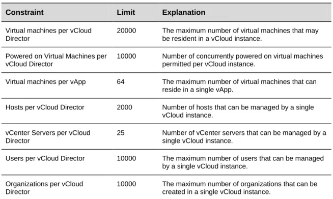
The maximum number of vShield Edge devices per vCenter Server is 1000. Table 7 lists vCloud Maximums based on a 10-cell configuration.
Table 7. vCloud Maximums
Constraint Limit Explanation
Virtual machines per vCloud Director
20000 The maximum number of virtual machines that may be resident in a vCloud instance.
Powered on Virtual Machines per vCloud Director
10000 Number of concurrently powered on virtual machines permitted per vCloud instance.
Virtual machines per vApp 64 The maximum number of virtual machines that can reside in a single vApp.
Hosts per vCloud Director 2000 Number of hosts that can be managed by a single vCloud instance.
vCenter Servers per vCloud Director
25 Number of vCenter servers that can be managed by a single vCloud instance.
Users per vCloud Director 10000 The maximum number of users that can be managed by a single vCloud instance.
Organizations per vCloud Director
10000 The maximum number of organizations that can be created in a single vCloud instance.
vApps per organization 500 The maximum number of vApps that can be deployed in a single organization.
Virtual datacenters per vCloud Director
10000 The maximum number of virtual datacenters that can be created in a single vCloud instance.
Datastores per vCloud Director 1024 Number of datastores that can be managed by a single vCloud instance.
Networks per vCloud Director 7500 The maximum number of logical networks that can be deployed in a single vCloud instance.
Catalogs per vCloud Director 1000 The maximum number of catalogs that can be created in a single vCloud instance.
Media Items per vCloud Director 1000 The maximum number of media items that can be created in a single vCloud instance.
.
See Configuration Maximums for VMware vSphere 5.0 for more information
5. vCloud Resource Design
Resource design for vCloud involves examining requirements to determine how best to partition and organize resources. With the commoditization of infrastructure resources, the ability to scale these fungible units up and down becomes increasingly important.
When designing for vCloud, keep in mind that the ultimate consumers of the product are the end-users of system. These users have a varying range of technical skills and experience, typically less than that of the architects and administrators of the vCloud environment. To encourage the use of vCloud computing as an effective tool, simplify user decision points where possible. If complexity is unavoidable, document all required steps to guide the end-users through a particular process.
Taking a top-down approach to vCloud design necessitates understanding of the new abstractions introduced in the vCloud API and how they map to traditional vSphere objects.
5.1 vCloud Director Constructs
VMware vCloud Director introduces logical constructs to facilitate multi-tenancy and provide interoperability between vCloud instances built to the vCloud API standard.
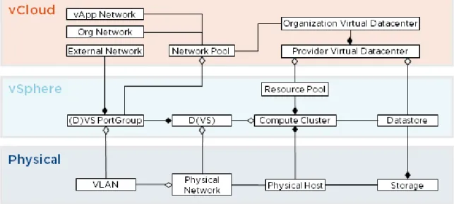
Figure 8 shows the logical constructs within vCloud Director that abstract underlying vSphere resources.
Table 8 provides descriptions of each construct.
Table 8. vCloud Director Constructs
Construct Definition
Organization The unit of mult-tenancy that represents a single logical security boundary. An organization contains users, virtual datacenters, and networks.
Provider virtual datacenter A grouping of compute and storage resources from a single vCenter Server. A provider virtual datacenter consists of a single resource pool and one or more datastores. Multiple organizations can share provider virtual datacenter resources.
Organization virtual datacenter A sub-grouping of compute and storage resources allocated from a provider virtual datacenter and assigned to a single organization. A virtual datacenter is a deployment environment where vApps can be instantiated, deployed, and powered on.
An organization virtual datacenter allocates resources using one of the following models:
• Pay-As-You-Go
• Reservation
• Allocation
Catalog A repository of vApp templates and media available to users for deployment. Catalogs can be published to all organizations in the same vCloud environment.
vApp A container for a software solution in the vCloud, and the standard unit of deployment for workloads in vCloud Director. vApps contain one or more virtual machines, have power-on operations, and can be imported or exported as an OVF.
External network External networks provide external connectivity to organization networks and are backed by port groups configured for Internet accessibility.
Organization network Organization networks are instantiated through network pools and bound to a single organization. Organization networks map to a vSphere port group and can be isolated, routed, or directly connected to an external network.
vApp network A network that connects virtual machines within a vApp, deployed by a consumer from a network pool. vApp networks can be directly
connected or routed to an organization network.
Network pool A network pool is a collection of isolated Layer 2 virtual networks available to vCloud Director for the automated deployment of private and NAT-routed networks.
5.2 Organizations
Organizations are the unit of multi-tenancy within vCloud Director and represent a single logical security boundary. Each organization contains a collection of end users, computing resources, catalogs, and vCloud workloads. For a public vCloud, vCloud Director organizations typically represent different customers. In a private vCloud, organizations can map to different department or business units. Each department or business unit may have several environments, such as development or production.
Organization users can be local users or imported from an LDAP server. LDAP integration can be specific to an organization or inherit the system LDAP configuration defined by the vCloud system administrator. For information about how to configure LDAP, see the vCloud Installation and Configuration Guide
organization to mitigate loss of administrative control due to LDAP authentication or connectivity issues. The name of the organization, specified during creation time, maps to a unique URL that allows access to the GUI for that organization. For example, an organization named NewCo maps to the following URL: https://<hostname>/cloud/org/NewCo. Use a standard naming convention for organization names and avoid using special characters or spaces because they affect the URL in undesirable ways. Use system defaults for most of the other organization settings, with the exception of leases, quotas, and limits. There are no specific requirements called out by the service definitions for these values—set them as needed.
5.2.1 Administrative Organization
A common best practice is to create an administrative organization. This organization provides a sandbox for system administrators and maintains a master catalog of vApp templates published to all other
organizations in the vCloud environment. Users in an organization typically consume resources by deploying vApps from a predefined catalog. The master catalog provides a global library of standardized vApp templates to promote reusability of common assets built to provider standards.
Administrators assigned to the administrative organization are responsible for creating standardized gold master vApp templates for inclusion in the master catalog. Place non-finalized vApps in a non-published internal catalog.
Configure the administrative organization to allow catalog publishing. Create a Pay-As-You-Go organization virtual datacenter to minimize the amount of resources reserved.
5.2.2 Standard Organizations
Create an organization for each tenant of the vCloud with the following considerations:
• Cannot publish catalogs.
5.2.3 Policies
Policies govern end-user behavior in vCloud environments. During the creation of an organization, policies can be set for the total number of running and stored virtual machines:
• Running VM quota refers to the maximum number of powered on virtual machines.
• Stored VM quota
Lease policies govern the persistence of vApps and vApp templates in an organization virtual datacenter. Specify the maximum length of time vApps can run and be stored in the organization virtual datacenters:
refers to the maximum number of all virtual machines, including powered off virtual machines.
• The maximum runtime lease specifies the amount of time vApps can run before vCloud Director automatically stops them.
• The storage lease specifies the amount of time vApps or vApp templates are stored before vCloud Director automatically performs storage cleanup.
• Lease policies can also be set to never expire.
When any option for storage lease except never expire is selected, the storage is automatically cleaned up. Storage cleanup options include:
• Permanently deleted – After the lease expires, the vApp or vApp template is automatically deleted.
• Moved to expired items – This flags the vApps or vApp templates for deletion. Items move to the expired items view where they are unusable unless the lease is renewed.
5.3 Provider Virtual Datacenter
The virtual datacenter• Define standard units of consumption. Variance in virtual datacenter allocations decreases manageability. Look at existing trends to determine common container sizes.
is a new construct that represents the standard container for a pool of compute and storage resources. There are two types of virtual datacenters: provider and organization. Provider virtual datacenters are composed of resource pools and datastores from a single vCenter Server. When creating a provider virtual datacenter, observe the following guidelines:
• Resource pools can map to a single provider virtual datacenter.
• If enough capacity exists, map the root resource pool of the cluster to provider virtual datacenters. This simplifies resource management. If the cluster expands, the backed provider virtual datacenter automatically grows as well. This is not the case if a standard resource pool is used. Multiple parent-level resource pools can add unnecessary complexity and lead to unpredictable results or inefficient use of resources if the reservations are not set appropriately.
• Create multiple provider virtual datacenters to differentiate computing levels or performance characteristics of a service offering. An example of differentiating by availability would be N+1 for a Bronze provider virtual datacenter versus N+2 for a Silver provider virtual datacenter.
• One or more datastores can be attached to a provider virtual datacenter. Multiple provider virtual datacenters can share the same datastore. For isolation and predictable storage growth, do not attach the same datastore to multiple provider virtual datacenters.
• Storage tiering is not possible within a provider virtual datacenter. Instead, supply tiered pools of storage through multiple provider virtual datacenters.
• As the number of hosts backing a provider virtual datacenter approaches the halfway mark of cluster limits, implement controls to preserve headroom and avoid reaching the cluster limits. For example, restrict the creation of additional tenants for this virtual datacenter and add additional hosts to accommodate increased resource demand for the existing tenants.
• If the cluster backing a provider virtual datacenter has reached the maximum number of hosts, create a new provider virtual datacenter associated with a separate cluster.
Refer to the private or public service definition for provider virtual datacenter sizing guidance. Consider:
• Expected number of virtual machines.
• Size of virtual machines (CPU, memory, storage).
There are cases where a “special purpose" provider virtual datacenter is viewed as “special purpose.” Special use-case provider virtual datacenters are a great example of what makes vCloud computing so flexible and powerful. The primary driver behind this need for a special purpose virtual datacenter is to satisfy the license restrictions imposed by software vendors that stipulate that all the processors that could run specific software must be licensed for it, regardless of whether or not they actually are running that software.
To keep licensing costs down while meeting the EULA requirements of such a software vendor, create a purpose-specific provider virtual datacenter backed by the minimum number of CPU sockets needed to achieve performance requirements. Create corresponding organization virtual datacenter per tenant, and provide prescriptive naming to guide users to deploy workloads accordingly.
5.3.1 Extending Virtual Datacenters
Rapid elasticity is one of the primary characteristics of vCloud computing. This involves quickly adding and releasing resources based on customer usage demands. vCloud Director 1.5 introduces the ability to expand a provider virtual datacenter by adding multiple resource pools.
Figure 9. Extending Virtual Datacenters
Considerations when extending a provider virtual datacenter:
• The primary resource pool is the resource pool used in the initial creation of the provider virtual datacenter.
• Reservation Pool and Allocation Pool virtual datacenters are bound to the primary resource pool and cannot draw resources from multiple resource pools.
• After creating a provider virtual datacenter, system administrators can add additional resource pools through the web console or vCloud API. This allows a provider virtual datacenter to draw resources from multiple resource pools.
• Resource pools added to existing provider virtual datacenters supply resources to Pay-As-You-Go organization virtual datacenter. Initially only Pay-As-You-Go virtual datacenters can draw from multiple resource pools. Elasticity is limited to a single vCenter datacenter. A provider virtual
datacenter can only draw resources from resource pools created in the same vCenter datacenter as the primary resource pool.
• Newly added resource pools may connect to datastores that have not been added to the provider virtual datacenter. Add all visible datastores to the provider virtual datacenter.
• Do not add extra resource pools from the same compute cluster that is already backing a provider virtual datacenter. Instead, increase the size of the existing resource pool that is mapped to the virtual datacenter.
• For elastic Pay-As-You-Go virtual datacenters, vCloud Director places the vApp in the resource pool with the most available constrained capacity.
5.4 Organization Virtual Datacenters
An organization virtual datacenter allocates resources from a provider virtual datacenter and makes it available for use for a given organization. Multiple organization virtual datacenters can share the resources of the same provider virtual datacenter.
Network pools provide network resources to organization virtual datacenters. When creating an organization virtual datacenter, select a network pool and specify the maximum allowable number of provisioned networks to allow users to self-provision vApp networks.
5.4.1 Allocation Models
Organizations can draw resources from multiple organization virtual datacenters using one of three resource allocation models: Reservation Pool, Allocation Pool, or Pay-As-You-Go.
5.4.1.1. Reservation Pool
Reservation Pool resources allocated to the organization virtual datacenter are completely dedicated. This is identical to an allocation pool with all guarantees set to 100%. Reservation pool virtual datacenters map to resource pools with the reservations set equivalent to the limits.
Figure 10. Reservation Pool
5.4.1.2. Allocation Pool
An Allocation Pool is a pool of allocated resources with a certain percentage guaranteed. The percentage guaranteed directly translates into reservations configured on the sub-resource pool. The difference between the reservation and the limit are resources that can be oversubscribed. In Figure 11, two tenants have organization virtual datacenters with 75% guaranteed. Resource usage of the two tenants cannot exceed the combined total of the reserved resources (75% for each) plus the resources available for overcommitment (25%). The percentage of resources guaranteed is not visible to end-consumers, who
Figure 11. Allocation Pool
5.4.1.3. Pay-As-You-Go
The Pay-As-You-Go model provides the illusion of an unlimited resource pool. This model maps to a sub-resource pool with no configured reservations or limits. Resources are committed only when vApps are deployed in the organization virtual datacenter.
Figure 12. Pay-As-You-Go
During the creation of an organization virtual datacenter, vCenter Server creates child resource pools with corresponding resource reservations and limits under the resource pool that represent the provider virtual datacenter.
For each vCloud tenant, review the applicable service definition to determine the number and types of organization virtual datacenters to create. Consider expected use cases, workload types, future capacity, and the maximum number of virtual machines per organization virtual datacenter.
Use prescriptive naming for organization virtual datacenters to guide expected user behavior. All users in an organization can view all allocated organization virtual datacenters.
Note
Pay-As-You-Go virtual datacenters have an additional setting called vCPU speed that translates into the limit of the vCPU on each virtual machine. VMware recommends increasing the default vCPU speed to a minimum of 1GHz.5.4.2 Thin Provisioning
Thin Provisioning allows oversubscription of datastores by presenting a virtual machine with more capacity than is physically allocated. For applications with predictable capacity growth, thin provisioning may provide a more efficient way of allocating capacity. When using thin provisioning, additional
management processes are required. Configure vCenter Server alarms to alert when approaching an out-of-space condition, providing for sufficient time to source and provision additional storage.
Thin provisioning is an available option when configuring organization virtual datacenters. vApps created after enabling thin provisioning use thin provisioned virtual disks.
5.4.3 Fast Provisioning
Fast provisioningFast provisioning benefits include:
is a new feature that enables rapid provisioning of vApps through vSphere 5 linked clone technology. A linked clone uses the same base disk as the original, with a chain of delta disks to keep track of the differences between the original and the clone. By default, fast provisioning is enabled when allocating storage to an organization virtual datacenter. Disabling fast provisioning on organization virtual datacenters results in full clones for subsequent vApp deployments.
• Increased elasticity – The ability to quickly provision vApps from a catalog using linked technology enable vCloud applications to scale up as needed.
• Increased operational efficiency – Usage of linked clones typically result in significant improvement in storage utilization.
Fast provisioning components are:
• Linked clone – Virtual machine created as a result of a copy operation, leveraging a redo-log based linked clone from the parent.
• Shadow VM – Full copy of the primary virtual machine used as the source for linked clone creation. A shadow VM allows cross-datastore provisioning, and is transparent to end-users. Shadow VMs are created for vApp templates only, not MyCloud vApps.
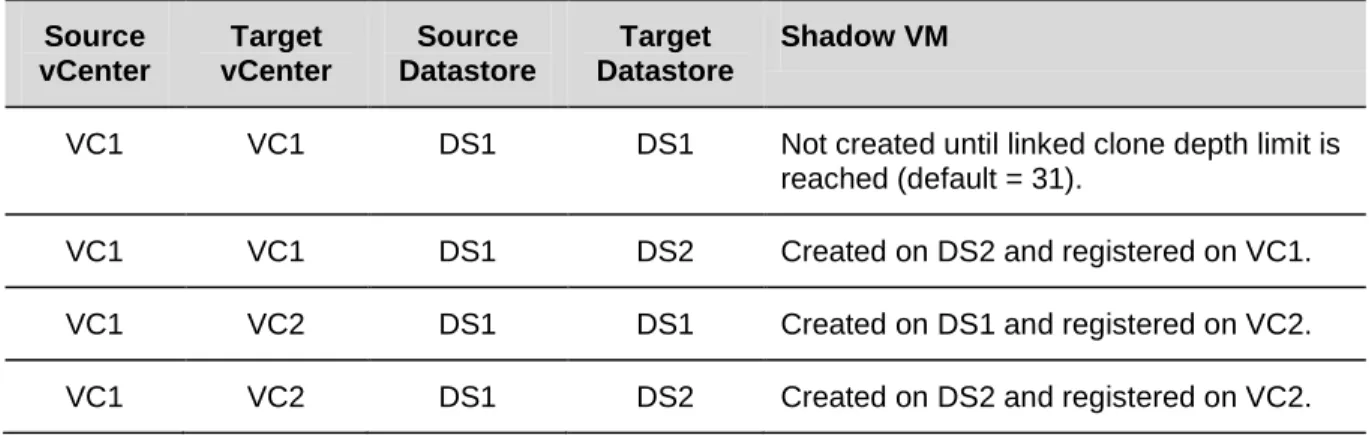
During fast provisioning, vApp files can land on the same virtual datacenter as the primary virtual machine or a different virtual datacenter. The choice of destination virtual datacenter impacts fast provisioning deployment based on the associated datastores and vCenter Servers, as shown in Table 9.
Table 9. Linked Clone Deployment Source
vCenter
Target vCenter
Source Datastore
Target Datastore
Shadow VM
VC1 VC1 DS1 DS1 Not created until linked clone depth limit is reached (default = 31).
VC1 VC1 DS1 DS2 Created on DS2 and registered on VC1.
VC1 VC2 DS1 DS1 Created on DS1 and registered on VC2.
VC1 VC2 DS1 DS2 Created on DS2 and registered on VC2.
Both source and target virtual datacenters have fast provisioning enabled. Linked clones created from VC1 use the primary virtual machine as the base disk. Linked clones created from VC2 use the shadow virtual machine as the base disk.
Fast Provisioning considerations:
• There is an 8-host cluster limit when using VMFS datastores.
• For clusters larger than eight hosts that require linked clones, use NFS datastores.
• Separate datastores reserved for fast provisioning from datastores reserved for full clones to improve performance and manageability.
• Fast provisioning requires vSphere 5 (vCenter Server 5 and ESXi 5).
• Provisioning time is nearly instantaneous when provisioning to the same datastore.
• Provisioning a virtual machine to a different datastore triggers creation of shadow VMs if one does not already exist on the target datastore.
• Shadow VMs are full copies of the source virtual machines, which factors into sizing considerations for pre-provisioning shadow VMs across datastores.
• Storage array caching can boost linked clone performance. Ample storage array cache greatly benefits an environment that utilizes linked clones.
• Although there is no limit to the width of a tree, datastores can fill up if a tree gets too wide. Use cross-datastore linked clones to mitigate this issue.
• The maximum linked clone chain length is 30. Further clones of the vApp result in full clones.
• Shadow VMs are treated differently from normal virtual machines and can be referenced through the vCloud API by the SHADOW_VM
• Only invoke Storage vMotion migration of linked clones through the vCloud API ( entity type.
Relocate_VM
• Avoid invoking Storage vMotion operations on linked clones through the vSphere Client as this consolidates the linked-clones and may result in inconsistent behavior.
call). The target virtual datacenter must have visibility to the datastore that contains the source disks.
Caution
Do not enable storage DRS on datastore clusters used with vCloud Director. If storage DRS enabled datastore as used as part of a provider virtual datacenter, linked clones may be migrated to another datastore in the provider virtual datacenter.5.4.4 vApp Placement Algorithm
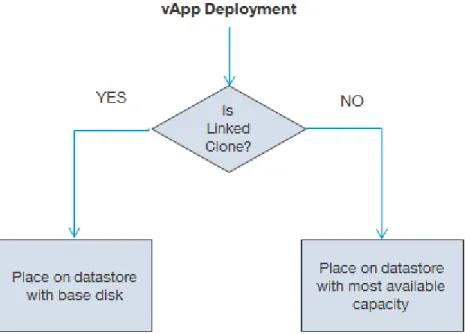
During vApp deployments, the virtual machine storage placement algorithm is as follows:
1. For fast provisioning-enabled virtual datacenters, find a datastore containing a base disk. If a base disk for the virtual machine exists, place a virtual machine on that datastore. The following conditions apply if the target datastore is reaching yellow or red disk thresholds.
• If base disk exists but target datastore exceeds red threshold, look for a normal or yellow-threshold datastore. If no suitable datastores are available, the operation will fail.
• If base disk exists but target datastore exceeds yellow threshold, look for a datastore that has not reached its yellow threshold. If none exists, deploy on the target datastore if capacity is sufficient. 2. If no base disk exists, place the virtual machine on the datastore with the most available capacity that
Figure 13 provides a flowchart of the vApp placement algorithm.
Figure 13. vApp Placement Algorithm
vApp creation fails if the vApp contains multiple virtual machines that cannot fit on a single datastore in the target virtual datacenter. Consider the following scenario:
Virtual Datacenter1:
Datastore1 – 30GB free space Datastore2 – 30GB free space vApp1 :
VM1 – 20GB VM2 – 30GB
Because the total size required for vApp1 exceeds the maximum available capacity of all datastores, the vApp deployment task fails. To mitigate this risk, follow VMware best practices for datastore utilization through proactive monitoring and storage maintenance.
5.4.5 Public vCloud Considerations
TheTable 10. Public vCloud Virtual Datacenter Requirements
Service Definition for a Public VMware vCloud provides some of the requirements used in this example.
Requirement
Three different service offerings are required: Basic (Pay-As-You-Go), Committed (Allocation Pool), Dedicated (Reservation Pool).
vCloud infrastructure to support a minimum of 1500 virtual machines across the three service offerings.
Split reservation pool into small, medium, and large pools with a split of 75%, 20%, and 5%.
• The Basic service offering uses the Pay-As-You-Go allocation model allowing customers to vary their resource usage while being charged for the resources that they consume.
• The Committed service offering uses the Allocation Pool model, which specifies a resource container size that has a certain percentage reserved.
• The Dedicated service offering uses the Reservation Pool model because this offering requires dedicated and guaranteed resources for the consumer.
The Service Definition for the Public VMware vCloud
The service definition provides detailed and descriptive guidance on how much a provider should charge for each service tier. VMware vCenter Chargeback integrates with vCloud Director to provide metering and cost calculation functionality. See the VMware vCenter Chargeback User’s Guide
has specific requirements for the maximum number of virtual machines each organization can have based on size. Refer to the service definition for the maximum virtual machine count for each virtual datacenter type
Using vCenter Chargeback with vCloud Director
details how to set up vCloud Director and vCenter Chargeback to accommodate instance-based pricing (Pay-As-You-Go), reservation-based pricing, and allocation-based pricing.