JUNOS® Software
MX-series Solutions Guide
Release 9.4
Juniper Networks, Inc.
1194 North Mathilda Avenue Sunnyvale, California 94089 USA408-745-2000
www.juniper.net
1989, 1991, 1992, 1993, 1994. The Regents of the University of California. All rights reserved.
GateD software copyright © 1995, the Regents of the University. All rights reserved. Gate Daemon was originated and developed through release 3.0 by Cornell University and its collaborators. Gated is based on Kirton’s EGP, UC Berkeley’s routing daemon (routed), and DCN’s HELLO routing protocol. Development of Gated has been supported in part by the National Science Foundation. Portions of the GateD software copyright © 1988, Regents of the University of California. All rights reserved. Portions of the GateD software copyright © 1991, D. L. S. Associates.
This product includes software developed by Maker Communications, Inc., copyright © 1996, 1997, Maker Communications, Inc.
Juniper Networks, the Juniper Networks logo, JUNOS, NetScreen, ScreenOS, and Steel-Belted Radius are registered trademarks of Juniper Networks, Inc. in the United States and other countries. JUNOSe is a trademark of Juniper Networks, Inc. All other trademarks, service marks, registered trademarks, or registered service marks are the property of their respective owners.
Juniper Networks assumes no responsibility for any inaccuracies in this document. Juniper Networks reserves the right to change, modify, transfer, or otherwise revise this publication without notice.
Products made or sold by Juniper Networks or components thereof might be covered by one or more of the following patents that are owned by or licensed to Juniper Networks: U.S. Patent Nos. 5,473,599, 5,905,725, 5,909,440, 6,192,051, 6,333,650, 6,359,479, 6,406,312, 6,429,706, 6,459,579, 6,493,347, 6,538,518, 6,538,899, 6,552,918, 6,567,902, 6,578,186, and 6,590,785.
JUNOS® Software MX-series Solutions Guide
Release 9.4
Copyright © 2009, Juniper Networks, Inc. All rights reserved. Printed in USA. Writing: Walter Goralski Editing: Sonia Saruba
Illustration: Nathaniel Woodward, Faith Bradford Cover Design: Edmonds Design
Revision History
15 January 2009—Revision 1
The information in this document is current as of the date listed in the revision history. YEAR 2000 NOTICE
Juniper Networks hardware and software products are Year 2000 compliant. The JUNOS software has no known time-related limitations through the year 2038. However, the NTP application is known to have some difficulty in the year 2036.
END USER LICENSE AGREEMENT
READ THIS END USER LICENSE AGREEMENT (“AGREEMENT”) BEFORE DOWNLOADING, INSTALLING, OR USING THE SOFTWARE. BY DOWNLOADING, INSTALLING, OR USING THE SOFTWARE OR OTHERWISE EXPRESSING YOUR AGREEMENT TO THE TERMS CONTAINED HEREIN, YOU (AS CUSTOMER OR IF YOU ARE NOT THE CUSTOMER, AS A REPRESENTATIVE/AGENT AUTHORIZED TO BIND THE CUSTOMER) CONSENT TO BE BOUND BY THIS AGREEMENT. IF YOU DO NOT OR CANNOT AGREE TO THE TERMS CONTAINED HEREIN, THEN (A) DO NOT DOWNLOAD, INSTALL, OR USE THE SOFTWARE, AND (B) YOU MAY CONTACT JUNIPER NETWORKS REGARDING LICENSE TERMS.
1. The Parties. The parties to this Agreement are (i) Juniper Networks, Inc. (if the Customer’s principal office is located in the Americas) or Juniper Networks (Cayman) Limited (if the Customer’s principal office is located outside the Americas) (such applicable entity being referred to herein as “Juniper”), and (ii) the person or organization that originally purchased from Juniper or an authorized Juniper reseller the applicable license(s) for use of the Software (“Customer”) (collectively, the “Parties”).
2. The Software. In this Agreement, “Software” means the program modules and features of the Juniper or Juniper-supplied software, for which Customer has paid the applicable license or support fees to Juniper or an authorized Juniper reseller, or which was embedded by Juniper in equipment which Customer purchased from Juniper or an authorized Juniper reseller. “Software” also includes updates, upgrades and new releases of such software. “Embedded Software” means Software which Juniper has embedded in or loaded onto the Juniper equipment and any updates, upgrades, additions or replacements which are subsequently embedded in or loaded onto the equipment.
3. License Grant. Subject to payment of the applicable fees and the limitations and restrictions set forth herein, Juniper grants to Customer a non-exclusive and non-transferable license, without right to sublicense, to use the Software, in executable form only, subject to the following use restrictions:
a. Customer shall use Embedded Software solely as embedded in, and for execution on, Juniper equipment originally purchased by Customer from Juniper or an authorized Juniper reseller.
b. Customer shall use the Software on a single hardware chassis having a single processing unit, or as many chassis or processing units for which Customer has paid the applicable license fees; provided, however, with respect to the Steel-Belted Radius or Odyssey Access Client software only, Customer shall use such Software on a single computer containing a single physical random access memory space and containing any number of processors. Use of the Steel-Belted Radius or IMS AAA software on multiple computers or virtual machines (e.g., Solaris zones) requires multiple licenses, regardless of whether such computers or virtualizations are physically contained on a single chassis.
c. Product purchase documents, paper or electronic user documentation, and/or the particular licenses purchased by Customer may specify limits to Customer’s use of the Software. Such limits may restrict use to a maximum number of seats, registered endpoints, concurrent users, sessions, calls, connections, subscribers, clusters, nodes, realms, devices, links, ports or transactions, or require the purchase of separate licenses to use particular features, functionalities, services, applications, operations, or capabilities, or provide throughput, performance, configuration, bandwidth, interface, processing, temporal, or geographical limits. In addition, such limits may restrict the use of the Software to managing certain kinds of networks or require the Software to be used only in conjunction with other specific Software. Customer’s use of the Software shall be subject to all such limitations and purchase of all applicable licenses.
d. For any trial copy of the Software, Customer’s right to use the Software expires 30 days after download, installation or use of the Software. Customer may operate the Software after the 30-day trial period only if Customer pays for a license to do so. Customer may not extend or create an additional trial period by re-installing the Software after the 30-day trial period.
e. The Global Enterprise Edition of the Steel-Belted Radius software may be used by Customer only to manage access to Customer’s enterprise network. Specifically, service provider customers are expressly prohibited from using the Global Enterprise Edition of the Steel-Belted Radius software to support any commercial network access services.
The foregoing license is not transferable or assignable by Customer. No license is granted herein to any user who did not originally purchase the applicable license(s) for the Software from Juniper or an authorized Juniper reseller.
4. Use Prohibitions. Notwithstanding the foregoing, the license provided herein does not permit the Customer to, and Customer agrees not to and shall not: (a) modify, unbundle, reverse engineer, or create derivative works based on the Software; (b) make unauthorized copies of the Software (except as necessary for backup purposes); (c) rent, sell, transfer, or grant any rights in and to any copy of the Software, in any form, to any third party; (d) remove any proprietary notices, labels, or marks on or in any copy of the Software or any product in which the Software is embedded; (e) distribute any copy of the Software to any third party, including as may be embedded in Juniper equipment sold in the secondhand market; (f) use any ‘locked’ or key-restricted feature, function, service, application, operation, or capability without first purchasing the applicable license(s) and obtaining a valid key from Juniper, even if such feature, function, service, application, operation, or capability is enabled without a key; (g) distribute any key for the Software provided by Juniper to any third party; (h) use the Software in any manner that extends or is broader than the uses purchased by Customer from Juniper or an authorized Juniper reseller; (i) use Embedded Software on non-Juniper equipment; (j) use Embedded Software (or make it available for use) on Juniper equipment that the Customer did not originally purchase from Juniper or an authorized Juniper reseller; (k) disclose the results of testing or benchmarking of the Software to any third party without the prior written consent of Juniper; or (l) use the Software in any manner other than as expressly provided herein.
5. Audit. Customer shall maintain accurate records as necessary to verify compliance with this Agreement. Upon request by Juniper, Customer shall furnish such records to Juniper and certify its compliance with this Agreement.
8. Warranty, Limitation of Liability, Disclaimer of Warranty. The warranty applicable to the Software shall be as set forth in the warranty statement that accompanies the Software (the “Warranty Statement”). Nothing in this Agreement shall give rise to any obligation to support the Software. Support services may be purchased separately. Any such support shall be governed by a separate, written support services agreement. TO THE MAXIMUM EXTENT PERMITTED BY LAW, JUNIPER SHALL NOT BE LIABLE FOR ANY LOST PROFITS, LOSS OF DATA, OR COSTS OR PROCUREMENT OF SUBSTITUTE GOODS OR SERVICES, OR FOR ANY SPECIAL, INDIRECT, OR CONSEQUENTIAL DAMAGES ARISING OUT OF THIS AGREEMENT, THE SOFTWARE, OR ANY JUNIPER OR JUNIPER-SUPPLIED SOFTWARE. IN NO EVENT SHALL JUNIPER BE LIABLE FOR DAMAGES ARISING FROM UNAUTHORIZED OR IMPROPER USE OF ANY JUNIPER OR JUNIPER-SUPPLIED SOFTWARE. EXCEPT AS EXPRESSLY PROVIDED IN THE WARRANTY STATEMENT TO THE EXTENT PERMITTED BY LAW, JUNIPER DISCLAIMS ANY AND ALL WARRANTIES IN AND TO THE SOFTWARE (WHETHER EXPRESS, IMPLIED, STATUTORY, OR OTHERWISE), INCLUDING ANY IMPLIED WARRANTY OF MERCHANTABILITY, FITNESS FOR A PARTICULAR PURPOSE, OR NONINFRINGEMENT. IN NO EVENT DOES JUNIPER WARRANT THAT THE SOFTWARE, OR ANY EQUIPMENT OR NETWORK RUNNING THE SOFTWARE, WILL OPERATE WITHOUT ERROR OR INTERRUPTION, OR WILL BE FREE OF VULNERABILITY TO INTRUSION OR ATTACK. In no event shall Juniper’s or its suppliers’ or licensors’ liability to Customer, whether in contract, tort (including negligence), breach of warranty, or otherwise, exceed the price paid by Customer for the Software that gave rise to the claim, or if the Software is embedded in another Juniper product, the price paid by Customer for such other product. Customer acknowledges and agrees that Juniper has set its prices and entered into this Agreement in reliance upon the disclaimers of warranty and the limitations of liability set forth herein, that the same reflect an allocation of risk between the Parties (including the risk that a contract remedy may fail of its essential purpose and cause consequential loss), and that the same form an essential basis of the bargain between the Parties.
9. Termination. Any breach of this Agreement or failure by Customer to pay any applicable fees due shall result in automatic termination of the license granted herein. Upon such termination, Customer shall destroy or return to Juniper all copies of the Software and related documentation in Customer’s possession or control.
10. Taxes. All license fees payable under this agreement are exclusive of tax. Customer shall be responsible for paying Taxes arising from the purchase of the license, or importation or use of the Software. If applicable, valid exemption documentation for each taxing jurisdiction shall be provided to Juniper prior to invoicing, and Customer shall promptly notify Juniper if their exemption is revoked or modified. All payments made by Customer shall be net of any applicable withholding tax. Customer will provide reasonable assistance to Juniper in connection with such withholding taxes by promptly: providing Juniper with valid tax receipts and other required documentation showing Customer’s payment of any withholding taxes; completing appropriate applications that would reduce the amount of withholding tax to be paid; and notifying and assisting Juniper in any audit or tax proceeding related to transactions hereunder. Customer shall comply with all applicable tax laws and regulations, and Customer will promptly pay or reimburse Juniper for all costs and damages related to any liability incurred by Juniper as a result of Customer’s non-compliance or delay with its responsibilities herein. Customer’s obligations under this Section shall survive termination or expiration of this Agreement.
11. Export. Customer agrees to comply with all applicable export laws and restrictions and regulations of any United States and any applicable foreign agency or authority, and not to export or re-export the Software or any direct product thereof in violation of any such restrictions, laws or regulations, or without all necessary approvals. Customer shall be liable for any such violations. The version of the Software supplied to Customer may contain encryption or other capabilities restricting Customer’s ability to export the Software without an export license.
12. Commercial Computer Software. The Software is “commercial computer software” and is provided with restricted rights. Use, duplication, or disclosure by the United States government is subject to restrictions set forth in this Agreement and as provided in DFARS 227.7201 through 227.7202-4, FAR 12.212, FAR 27.405(b)(2), FAR 52.227-19, or FAR 52.227-14(ALT III) as applicable.
13. Interface Information. To the extent required by applicable law, and at Customer's written request, Juniper shall provide Customer with the interface information needed to achieve interoperability between the Software and another independently created program, on payment of applicable fee, if any. Customer shall observe strict obligations of confidentiality with respect to such information and shall use such information in compliance with any applicable terms and conditions upon which Juniper makes such information available.
14. Third Party Software. Any licensor of Juniper whose software is embedded in the Software and any supplier of Juniper whose products or technology are embedded in (or services are accessed by) the Software shall be a third party beneficiary with respect to this Agreement, and such licensor or vendor shall have the right to enforce this Agreement in its own name as if it were Juniper. In addition, certain third party software may be provided with the Software and is subject to the accompanying license(s), if any, of its respective owner(s). To the extent portions of the Software are distributed under and subject to open source licenses obligating Juniper to make the source code for such portions publicly available (such as the GNU General Public License (“GPL”) or the GNU Library General Public License (“LGPL”)), Juniper will make such source code portions (including Juniper modifications, as appropriate) available upon request for a period of up to three years from the date of distribution. Such request can be made in writing to Juniper Networks, Inc., 1194 N. Mathilda Ave., Sunnyvale, CA 94089, ATTN: General Counsel. You may obtain a copy of the GPL at http://www.gnu.org/licenses/gpl.html, and a copy of the LGPL at http://www.gnu.org/licenses/lgpl.html.
15. Miscellaneous. This Agreement shall be governed by the laws of the State of California without reference to its conflicts of laws principles. The provisions of the U.N. Convention for the International Sale of Goods shall not apply to this Agreement. For any disputes arising under this Agreement, the Parties hereby consent to the personal and exclusive jurisdiction of, and venue in, the state and federal courts within Santa Clara County, California. This Agreement constitutes the entire and sole agreement between Juniper and the Customer with respect to the Software, and supersedes all prior and contemporaneous
agreements relating to the Software, whether oral or written (including any inconsistent terms contained in a purchase order), except that the terms of a separate written agreement executed by an authorized Juniper representative and Customer shall govern to the extent such terms are inconsistent or conflict with terms contained herein. No modification to this Agreement nor any waiver of any rights hereunder shall be effective unless expressly assented to in writing by the party to be charged. If any portion of this Agreement is held invalid, the Parties agree that such invalidity shall not affect the validity of the remainder of this Agreement. This Agreement and associated documentation has been written in the English language, and the Parties agree that the English version will govern. (For Canada: Les parties aux présentés confirment leur volonté que cette convention de même que tous les documents y compris tout avis qui s'y rattaché, soient redigés en langue anglaise. (Translation: The parties confirm that this Agreement and all related documentation is and will be in the English language)).
Abbreviated Table of Contents
About This Guide xvii
Part 1
Overview
Chapter 1 Overview of Ethernet Solutions 3
Part 2
Solutions for MX-series
Chapter 2 Configuring Basic MX-series Layer 2 Features 17 Chapter 3 Virtual Switches 33 Chapter 4 VLAN Configuration for VPLS and Bridge Domains 35 Chapter 5 MX-series Examples Using VLANs and VPLS 39 Chapter 6 Configuring Ethernet OAM 51 Chapter 7 Configuring MX-series Ethernet Ring Protection 73 Chapter 8 Configuring MX-series Filters 85 Chapter 9 Configuring MX-series DHCP Relay 91
Part 3
Index
Index 97
Table of Contents
About This Guide xvii
Objectives ...xvii
Audience ...xvii
Supported Routing Platforms ...xviii
Using the Indexes ...xviii
Using the Examples in This Manual ...xviii
Merging a Full Example ...xix
Merging a Snippet ...xix
Documentation Conventions ...xx
List of Technical Publications ...xxii
Documentation Feedback ...xxviii
Requesting Technical Support ...xxix
Part 1
Overview
Chapter 1 Overview of Ethernet Solutions 3 Terminology and Acronyms ...3Networking and Internetworking with Bridges and Routers ...5
Addresses at L2 and L3 ...6
The Benefits of Ethernet ...8
Handling MAC Addresses ...8
MAC Addresses, VLAN Tags, and Forwarding ...9
Nesting VLAN Tags ...10
Metro Ethernet Network ...11
Layer 2 Interface Types ...14
Part 2
Solutions for MX-series
Chapter 2 Configuring Basic MX-series Layer 2 Features 17 Configuring the Interfaces and VLAN Tags ...19Configuring Bridge Domains ...24
Configuring Spanning Tree Protocols ...26
Configuring Integrated Bridging and Routing ...28
Chapter 3 Virtual Switches 33
Overview of Virtual Switches ...33
Configuring Virtual Switches ...34
Chapter 4 VLAN Configuration for VPLS and Bridge Domains 35 VLAN Translation (Normalization) ...36
Implicit VLAN Translation to a Normalized VLAN ...36
Sending Tagged or Untagged Packets over VPLS Virtual Interfaces ...37
Creating Implicit Learning Domains ...37
Bridging Packet Flow ...37
Configuring a Normalized VLAN ...38
Chapter 5 MX-series Examples Using VLANs and VPLS 39 Provider Bridge Network with Normalized VLAN Tags ...39
VPLS Labels and VLAN Tags ...43
One VPLS Instance for Several VLANs ...47
Chapter 6 Configuring Ethernet OAM 51 Overview of Ethernet OAM ...51
Ethernet CFM over VPLS ...53
Ethernet CFM on Bridge Connections ...60
Ethernet CFM on Physical Interfaces ...63
Ethernet LFM ...65
Ethernet LFM Between PE and CE ...65
Ethernet LFM for CCC ...67
Ethernet LFM for Aggregated Ethernet ...68
Ethernet LFM with Loopback Support ...69
Chapter 7 Configuring MX-series Ethernet Ring Protection 73 Ethernet Ring Protection Overview ...73
Example: MX-series Ethernet Ring Protection ...74
MX-series Ring Protection Operation—Normal Conditions ...80
MX-series Ring Protection Operation—Failure Condition ...82
Chapter 8 Configuring MX-series Filters 85 Policing and Marking Traffic Entering a VPLS Core ...86
Filtering Frames by MAC Address ...87
Filtering Frames by IEEE 802.1p Bits ...88
Filtering Frames by Packet Loss Priority ...89
Chapter 9 Configuring MX-series DHCP Relay 91 DHCP Relay and MX-series Overview ...91 Configuring DHCP Relay on the MX-series ...92 Configuring DHCP Relay with a Bridge Domain VLAN ...92
Part 3
Index
Index ...97
Table of Contents ■ xi Table of Contents
List of Figures
Figure 1: Native (Normal) and VLAN-Tagged Ethernet Fames ...9
Figure 2: A Metro Ethernet Network ...12
Figure 3: A Metro Ethernet Network with MX-series Routers ...13
Figure 4: VLAN Tags on a Metro Ethernet Network ...13
Figure 5: Bridging Network with MX-series Routers ...18
Figure 6: Designated, Root, and Alternate Ports ...28
Figure 7: Provider Bridge Network Using Normalized VLAN Tags ...40
Figure 8: VLAN Tags and VPLS Labels ...44
Figure 9: Many VLANs on One VPLS Instance ...47
Figure 10: Ethernet OAM with VPLS ...54
Figure 11: Ethernet CFM over a Bridge Network ...60
Figure 12: Ethernet CFM on Physical Interfaces ...64
Figure 13: Ethernet LFM Between PE and CE ...66
Figure 14: Ethernet LFM for CCC ...67
Figure 15: Ethernet LFM for Aggregated Ethernet ...68
Figure 16: Ethernet LFM with Loopback Support ...70
Figure 17: Ethernet Ring Protection Example Nodes ...75
Figure 18: Policing and Marking Traffic Entering a VPLS Core ...86
List of Tables
Table 1: Notice Icons ...xx
Table 2: Text and Syntax Conventions ...xx
Table 3: Technical Documentation for Supported Routing Platforms ...xxii
Table 4: JUNOS Software Network Operations Guides ...xxvi
Table 5: JUNOS Software for J-series Services Routers and SRX-series Services Gateways Documentation ...xxvii
Table 6: Additional Books Available Through http://www.juniper.net/books ...xxviii
About This Guide
This preface provides the following guidelines for using the JUNOS® Software MX-series Solutions Guide:
■ Objectives on page xvii ■ Audience on page xvii
■ Supported Routing Platforms on page xviii ■ Using the Indexes on page xviii
■ Using the Examples in This Manual on page xviii ■ Documentation Conventions on page xx
■ List of Technical Publications on page xxii ■ Documentation Feedback on page xxviii ■ Requesting Technical Support on page xxix
Objectives
This guide provides an overview of the Layer 2 features of the MX-series routers and describes how to configure the features to provide solutions to several network scenarios.
NOTE: This guide documents Release 9.4 of the JUNOS software. For additional information about the JUNOS software—either corrections to or information that might have been omitted from this guide—see the software release notes at http://www.juniper.net/.
Audience
This guide is designed for network administrators who are configuring and monitoring a Juniper Networks MX-series routing platform.
To use this guide, you need a broad understanding of networks in general, the Internet in particular, networking principles, and network configuration. You must also be familiar with one or more of the following Internet routing protocols:
■ Border Gateway Protocol (BGP)
■ Distance Vector Multicast Routing Protocol (DVMRP)
■ Intermediate System-to-Intermediate System (IS-IS) ■ Internet Control Message Protocol (ICMP) router discovery ■ Internet Group Management Protocol (IGMP)
■ Multiprotocol Label Switching (MPLS) ■ Open Shortest Path First (OSPF) ■ Protocol-Independent Multicast (PIM) ■ Resource Reservation Protocol (RSVP) ■ Routing Information Protocol (RIP)
■ Simple Network Management Protocol (SNMP)
Personnel operating the equipment must be trained and competent; must not conduct themselves in a careless, willfully negligent, or hostile manner; and must abide by the instructions provided by the documentation.
Supported Routing Platforms
For the Layer 2 features described in this manual, the JUNOS software currently supports the following routing platforms:
■ MX-series
Using the Indexes
This reference contains two indexes: a complete index that includes topic entries, and an index of statements and commands only.
In the index of statements and commands, an entry refers to a statement summary section only. In the complete index, the entry for a configuration statement or command contains at least two parts:
■ The primary entry refers to the statement summary section.
■ The secondary entry, usage guidelines, refers to the section in a configuration guidelines chapter that describes how to use the statement or command.
Using the Examples in This Manual
If you want to use the examples in this manual, you can use the load merge or the
load merge relative command. These commands cause the software to merge the incoming configuration into the current candidate configuration. If the example configuration contains the top level of the hierarchy (or multiple hierarchies), the example is a full example. In this case, use the load merge command.
If the example configuration does not start at the top level of the hierarchy, the example is a snippet. In this case, use the load merge relative command. These procedures are described in the following sections.
Merging a Full Example
To merge a full example, follow these steps:
1. From the HTML or PDF version of the manual, copy a configuration example into a text file, save the file with a name, and copy the file to a directory on your routing platform.
For example, copy the following configuration to a file and name the file
ex-script.conf. Copy the ex-script.conf file to the /var/tmp directory on your routing platform.
system { scripts {
commit {
file ex-script.xsl; }
} }
interfaces { fxp0 {
disable; unit 0 {
family inet {
address 10.0.0.1/24; }
} } }
2. Merge the contents of the file into your routing platform configuration by issuing the load merge configuration mode command:
[edit]
user@host# load merge /var/tmp/ex-script.conf
load complete
Merging a Snippet
To merge a snippet, follow these steps:
1. From the HTML or PDF version of the manual, copy a configuration snippet into a text file, save the file with a name, and copy the file to a directory on your routing platform.
For example, copy the following snippet to a file and name the file
ex-script-snippet.conf. Copy the ex-script-snippet.conf file to the /var/tmp directory on your routing platform.
commit {
file ex-script-snippet.xsl; }
2. Move to the hierarchy level that is relevant for this snippet by issuing the following configuration mode command:
Using the Examples in This Manual ■ xix About This Guide
[edit]
user@host# edit system scripts
[edit system scripts]
3. Merge the contents of the file into your routing platform configuration by issuing the load merge relative configuration mode command:
[edit system scripts]
user@host# load merge relative /var/tmp/ex-script-snippet.conf
load complete
For more information about the load command, see the JUNOS CLI User Guide.
Documentation Conventions
Table 1 on page xx defines notice icons used in this guide. Table 1: Notice Icons
Description Meaning
Icon
Indicates important features or instructions. Informational note
Indicates a situation that might result in loss of data or hardware damage. Caution
Alerts you to the risk of personal injury or death. Warning
Alerts you to the risk of personal injury from a laser. Laser warning
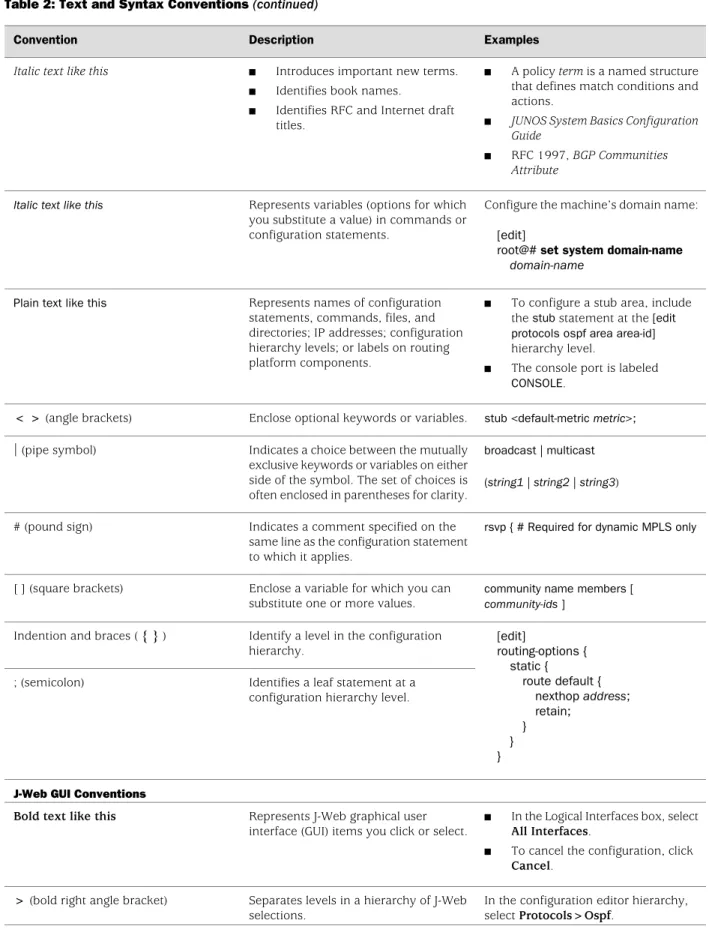
Table 2 on page xx defines the text and syntax conventions used in this guide. Table 2: Text and Syntax Conventions
Examples Description
Convention
To enter configuration mode, type the configure command:
user@host> configure
Represents text that you type. Bold text like this
user@host> show chassis alarms
No alarms currently active Represents output that appears on the
terminal screen. Fixed-width text like this
Table 2: Text and Syntax Conventions (continued)
Examples Description
Convention
■ A policy term is a named structure that defines match conditions and actions.
■ JUNOS System Basics Configuration Guide
■ RFC 1997, BGP Communities Attribute
■ Introduces important new terms. ■ Identifies book names.
■ Identifies RFC and Internet draft titles.
Italic text like this
Configure the machine’s domain name: [edit]
root@# set system domain-name
domain-name Represents variables (options for which
you substitute a value) in commands or configuration statements.
Italic text like this
■ To configure a stub area, include the stub statement at the [edit protocols ospf area area-id] hierarchy level.
■ The console port is labeled CONSOLE.
Represents names of configuration statements, commands, files, and directories; IP addresses; configuration hierarchy levels; or labels on routing platform components.
Plain text like this
stub <default-metric metric>; Enclose optional keywords or variables.
< > (angle brackets)
broadcast | multicast
(string1 | string2 | string3) Indicates a choice between the mutually
exclusive keywords or variables on either side of the symbol. The set of choices is often enclosed in parentheses for clarity. | (pipe symbol)
rsvp { # Required for dynamic MPLS only Indicates a comment specified on the
same line as the configuration statement to which it applies.
# (pound sign)
community name members [ community-ids ]
Enclose a variable for which you can substitute one or more values. [ ] (square brackets)
[edit]
routing-options { static {
route default { nexthop address; retain;
} } } Identify a level in the configuration
hierarchy. Indention and braces ( { } )
Identifies a leaf statement at a configuration hierarchy level. ; (semicolon)
J-Web GUI Conventions
■ In the Logical Interfaces box, select All Interfaces.
■ To cancel the configuration, click Cancel.
Represents J-Web graphical user interface (GUI) items you click or select. Bold text like this
In the configuration editor hierarchy, select Protocols>Ospf.
Separates levels in a hierarchy of J-Web selections.
> (bold right angle bracket)
Documentation Conventions ■ xxi About This Guide
List of Technical Publications
Table 3 on page xxii lists the software and hardware guides and release notes for Juniper Networks M-series, MX-series, and T-series routing platforms and describes the contents of each document. Table 4 on page xxvi lists the books included in the
Network Operations Guide series. Table 5 on page xxvii lists the manuals and release notes supporting JUNOS software for J-series and SRX-series platforms. All documents are available at http://www.juniper.net/techpubs/.
Table 6 on page xxviii lists additional books on Juniper Networks solutions that you can order through your bookstore. A complete list of such books is available at
http://www.juniper.net/books.
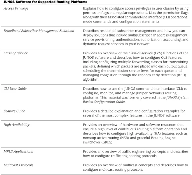
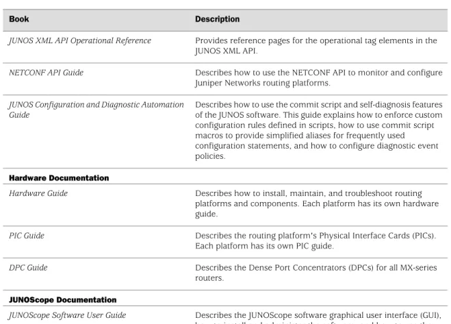
Table 3: Technical Documentation for Supported Routing Platforms Description
Book
JUNOS Software for Supported Routing Platforms
Explains how to configure access privileges in user classes by using permission flags and regular expressions. Lists the permission flags along with their associated command-line interface (CLI) operational mode commands and configuration statements.
Access Privilege
Describes residential subscriber management and how you can deploy solutions that include multisubscriber IP address assignment, service provisioning, authentication, authorization, accounting, and dynamic request services in your network
Broadband Subscriber Management Solutions
Provides an overview of the class-of-service (CoS) functions of the JUNOS software and describes how to configure CoS features, including configuring multiple forwarding classes for transmitting packets, defining which packets are placed into each output queue, scheduling the transmission service level for each queue, and managing congestion through the random early detection (RED) algorithm.
Class of Service
Describes how to use the JUNOS command-line interface (CLI) to configure, monitor, and manage Juniper Networks routing platforms. This material was formerly covered in the JUNOS System Basics Configuration Guide.
CLI User Guide
Provides a detailed explanation and configuration examples for several of the most complex features in the JUNOS software.
Feature Guide
Provides an overview of hardware and software resources that ensure a high level of continuous routing platform operation and describes how to configure high availability (HA) features such as nonstop active routing (NSR) and graceful Routing Engine switchover (GRES).
High Availability
Provides an overview of traffic engineering concepts and describes how to configure traffic engineering protocols.
MPLS Applications
Provides an overview of multicast concepts and describes how to configure multicast routing protocols.
Multicast Protocols
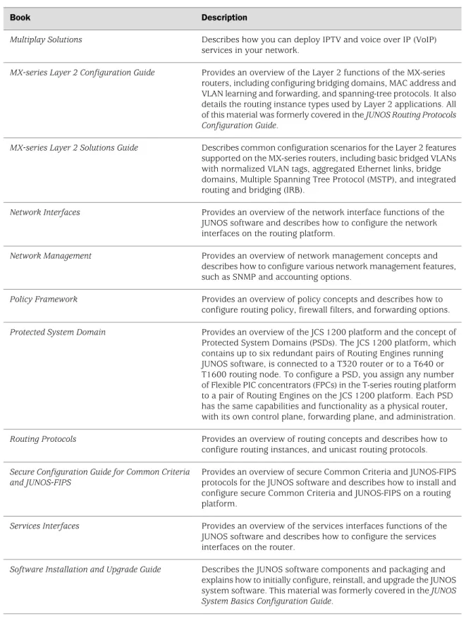
Table 3: Technical Documentation for Supported Routing Platforms (continued)
Description Book
Describes how you can deploy IPTV and voice over IP (VoIP) services in your network.
Multiplay Solutions
Provides an overview of the Layer 2 functions of the MX-series routers, including configuring bridging domains, MAC address and VLAN learning and forwarding, and spanning-tree protocols. It also details the routing instance types used by Layer 2 applications. All of this material was formerly covered in the JUNOS Routing Protocols Configuration Guide.
MX-series Layer 2 Configuration Guide
Describes common configuration scenarios for the Layer 2 features supported on the MX-series routers, including basic bridged VLANs with normalized VLAN tags, aggregated Ethernet links, bridge domains, Multiple Spanning Tree Protocol (MSTP), and integrated routing and bridging (IRB).
MX-series Layer 2 Solutions Guide
Provides an overview of the network interface functions of the JUNOS software and describes how to configure the network interfaces on the routing platform.
Network Interfaces
Provides an overview of network management concepts and describes how to configure various network management features, such as SNMP and accounting options.
Network Management
Provides an overview of policy concepts and describes how to configure routing policy, firewall filters, and forwarding options.
Policy Framework
Provides an overview of the JCS 1200 platform and the concept of Protected System Domains (PSDs). The JCS 1200 platform, which contains up to six redundant pairs of Routing Engines running JUNOS software, is connected to a T320 router or to a T640 or T1600 routing node. To configure a PSD, you assign any number of Flexible PIC concentrators (FPCs) in the T-series routing platform to a pair of Routing Engines on the JCS 1200 platform. Each PSD has the same capabilities and functionality as a physical router, with its own control plane, forwarding plane, and administration.
Protected System Domain
Provides an overview of routing concepts and describes how to configure routing instances, and unicast routing protocols.
Routing Protocols
Provides an overview of secure Common Criteria and JUNOS-FIPS protocols for the JUNOS software and describes how to install and configure secure Common Criteria and JUNOS-FIPS on a routing platform.
Secure Configuration Guide for Common Criteria and JUNOS-FIPS
Provides an overview of the services interfaces functions of the JUNOS software and describes how to configure the services interfaces on the router.
Services Interfaces
Describes the JUNOS software components and packaging and explains how to initially configure, reinstall, and upgrade the JUNOS system software. This material was formerly covered in the JUNOS System Basics Configuration Guide.
Software Installation and Upgrade Guide
List of Technical Publications ■ xxiii About This Guide
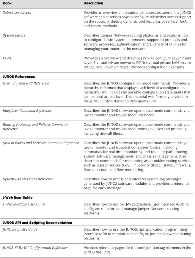
Table 3: Technical Documentation for Supported Routing Platforms (continued)
Description Book
Provides an overview of the subscriber access features of the JUNOS software and describes how to configure subscriber access support on the router, including dynamic profiles, class of service, AAA, and access methods.
Subscriber Access
Describes Juniper Networks routing platforms and explains how to configure basic system parameters, supported protocols and software processes, authentication, and a variety of utilities for managing your router on the network.
System Basics
Provides an overview and describes how to configure Layer 2 and Layer 3 virtual private networks (VPNs), virtual private LAN service (VPLS), and Layer 2 circuits. Provides configuration examples.
VPNs
JUNOS References
Describes the JUNOS configuration mode commands. Provides a hierarchy reference that displays each level of a configuration hierarchy, and includes all possible configuration statements that can be used at that level. This material was formerly covered in the JUNOS System Basics Configuration Guide.
Hierarchy and RFC Reference
Describes the JUNOS software operational mode commands you use to monitor and troubleshoot interfaces.
Interfaces Command Reference
Describes the JUNOS software operational mode commands you use to monitor and troubleshoot routing policies and protocols, including firewall filters.
Routing Protocols and Policies Command Reference
Describes the JUNOS software operational mode commands you use to monitor and troubleshoot system basics, including commands for real-time monitoring and route (or path) tracing, system software management, and chassis management. Also describes commands for monitoring and troubleshooting services such as class of service (CoS), IP Security (IPsec), stateful firewalls, flow collection, and flow monitoring.
System Basics and Services Command Reference
Describes how to access and interpret system log messages generated by JUNOS software modules and provides a reference page for each message.
System Log Messages Reference
J-Web User Guide
Describes how to use the J-Web graphical user interface (GUI) to configure, monitor, and manage Juniper Networks routing platforms.
J-Web Interface User Guide
JUNOS API and Scripting Documentation
Describes how to use the JUNOScript application programming interface (API) to monitor and configure Juniper Networks routing platforms.
JUNOScript API Guide
Provides reference pages for the configuration tag elements in the JUNOS XML API.
JUNOS XML API Configuration Reference
Table 3: Technical Documentation for Supported Routing Platforms (continued)
Description Book
Provides reference pages for the operational tag elements in the JUNOS XML API.
JUNOS XML API Operational Reference
Describes how to use the NETCONF API to monitor and configure Juniper Networks routing platforms.
NETCONF API Guide
Describes how to use the commit script and self-diagnosis features of the JUNOS software. This guide explains how to enforce custom configuration rules defined in scripts, how to use commit script macros to provide simplified aliases for frequently used configuration statements, and how to configure diagnostic event policies.
JUNOS Configuration and Diagnostic Automation Guide
Hardware Documentation
Describes how to install, maintain, and troubleshoot routing platforms and components. Each platform has its own hardware guide.
Hardware Guide
Describes the routing platform's Physical Interface Cards (PICs). Each platform has its own PIC guide.
PIC Guide
Describes the Dense Port Concentrators (DPCs) for all MX-series routers.
DPC Guide
JUNOScope Documentation
Describes the JUNOScope software graphical user interface (GUI), how to install and administer the software, and how to use the software to manage routing platform configuration files and monitor routing platform operations.
JUNOScope Software User Guide
Advanced Insight Solutions (AIS) Documentation
Describes the Advanced Insight Manager (AIM) application, which provides a gateway between JUNOS devices and Juniper Support Systems (JSS) for case management and intelligence updates. Explains how to run AI-Scripts on Juniper Networks devices.
Advanced Insight Solutions Guide
Release Notes
Summarize new features and known problems for a particular software release, provide corrections and updates to published JUNOS, JUNOScript, and NETCONF manuals, provide information that might have been omitted from the manuals, and describe upgrade and downgrade procedures.
JUNOS Release Notes
Describe the available documentation for the routing platform and summarize known problems with the hardware and accompanying software. Each platform has its own release notes.
Hardware Release Notes
Contain corrections and updates to the published JUNOScope manual, provide information that might have been omitted from the manual, and describe upgrade and downgrade procedures.
JUNOScope Release Notes
List of Technical Publications ■ xxv About This Guide
Table 3: Technical Documentation for Supported Routing Platforms (continued)
Description Book
Summarize AIS new features and guidelines, identify known and resolved problems, provide information that might have been omitted from the manuals, and provide initial setup, upgrade, and downgrade procedures.
AIS Release Notes
Summarize AI-Scripts new features, identify known and resolved problems, provide information that might have been omitted from the manuals, and provide instructions for automatic and manual installation, including deleting and rolling back.
AIS AI-Scripts Release Notes
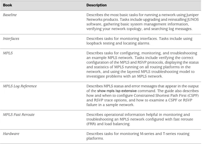
Table 4: JUNOS Software Network Operations Guides Description Book
Describes the most basic tasks for running a network using Juniper Networks products. Tasks include upgrading and reinstalling JUNOS software, gathering basic system management information, verifying your network topology, and searching log messages.
Baseline
Describes tasks for monitoring interfaces. Tasks include using loopback testing and locating alarms.
Interfaces
Describes tasks for configuring, monitoring, and troubleshooting an example MPLS network. Tasks include verifying the correct configuration of the MPLS and RSVP protocols, displaying the status and statistics of MPLS running on all routing platforms in the network, and using the layered MPLS troubleshooting model to investigate problems with an MPLS network.
MPLS
Describes MPLS status and error messages that appear in the output of the show mpls lsp extensive command. The guide also describes how and when to configure Constrained Shortest Path First (CSPF) and RSVP trace options, and how to examine a CSPF or RSVP failure in a sample network.
MPLS Log Reference
Describes operational information helpful in monitoring and troubleshooting an MPLS network configured with fast reroute (FRR) and load balancing.
MPLS Fast Reroute
Describes tasks for monitoring M-series and T-series routing platforms.
Hardware
To configure and operate a J-series Services Router or an SRX-series Services Gateway running JUNOS software, you must also use the configuration statements and operational mode commands documented in JUNOS configuration guides and command references. To configure and operate a WX Integrated Services Module, you must also use WX documentation.
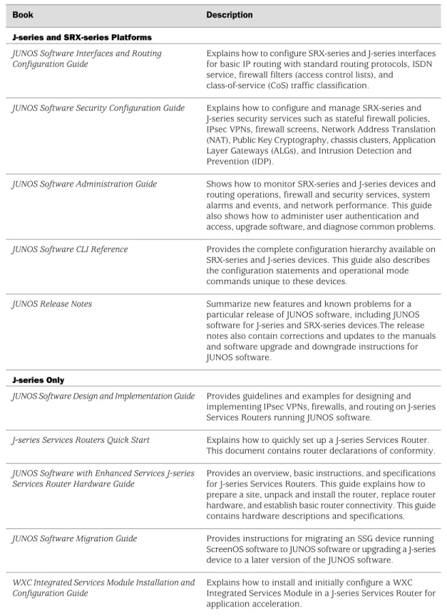
Table 5: JUNOS Software for J-series Services Routers and SRX-series Services Gateways Documentation
Description Book
J-series and SRX-series Platforms
Explains how to configure SRX-series and J-series interfaces for basic IP routing with standard routing protocols, ISDN service, firewall filters (access control lists), and
class-of-service (CoS) traffic classification.
JUNOS Software Interfaces and Routing Configuration Guide
Explains how to configure and manage SRX-series and J-series security services such as stateful firewall policies, IPsec VPNs, firewall screens, Network Address Translation (NAT), Public Key Cryptography, chassis clusters, Application Layer Gateways (ALGs), and Intrusion Detection and Prevention (IDP).
JUNOS Software Security Configuration Guide
Shows how to monitor SRX-series and J-series devices and routing operations, firewall and security services, system alarms and events, and network performance. This guide also shows how to administer user authentication and access, upgrade software, and diagnose common problems.
JUNOS Software Administration Guide
Provides the complete configuration hierarchy available on SRX-series and J-series devices. This guide also describes the configuration statements and operational mode commands unique to these devices.
JUNOS Software CLI Reference
Summarize new features and known problems for a particular release of JUNOS software, including JUNOS software for J-series and SRX-series devices.The release notes also contain corrections and updates to the manuals and software upgrade and downgrade instructions for JUNOS software.
JUNOS Release Notes
J-series Only
Provides guidelines and examples for designing and implementing IPsec VPNs, firewalls, and routing on J-series Services Routers running JUNOS software.
JUNOS Software Design and Implementation Guide
Explains how to quickly set up a J-series Services Router. This document contains router declarations of conformity.
J-series Services Routers Quick Start
Provides an overview, basic instructions, and specifications for J-series Services Routers. This guide explains how to prepare a site, unpack and install the router, replace router hardware, and establish basic router connectivity. This guide contains hardware descriptions and specifications.
JUNOS Software with Enhanced Services J-series Services Router Hardware Guide
Provides instructions for migrating an SSG device running ScreenOS software to JUNOS software or upgrading a J-series device to a later version of the JUNOS software.
JUNOS Software Migration Guide
Explains how to install and initially configure a WXC Integrated Services Module in a J-series Services Router for application acceleration.
WXC Integrated Services Module Installation and Configuration Guide
List of Technical Publications ■ xxvii About This Guide
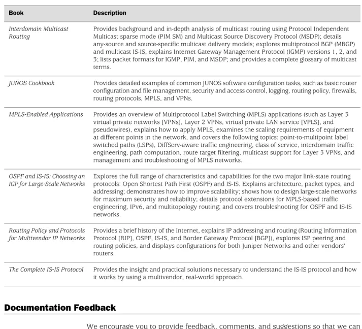
Table 6: Additional Books Available Through http://www.juniper.net/books Description
Book
Provides background and in-depth analysis of multicast routing using Protocol Independent Multicast sparse mode (PIM SM) and Multicast Source Discovery Protocol (MSDP); details any-source and source-specific multicast delivery models; explores multiprotocol BGP (MBGP) and multicast IS-IS; explains Internet Gateway Management Protocol (IGMP) versions 1, 2, and 3; lists packet formats for IGMP, PIM, and MSDP; and provides a complete glossary of multicast terms.
Interdomain Multicast Routing
Provides detailed examples of common JUNOS software configuration tasks, such as basic router configuration and file management, security and access control, logging, routing policy, firewalls, routing protocols, MPLS, and VPNs.
JUNOS Cookbook
Provides an overview of Multiprotocol Label Switching (MPLS) applications (such as Layer 3 virtual private networks [VPNs], Layer 2 VPNs, virtual private LAN service [VPLS], and pseudowires), explains how to apply MPLS, examines the scaling requirements of equipment at different points in the network, and covers the following topics: point-to-multipoint label switched paths (LSPs), DiffServ-aware traffic engineering, class of service, interdomain traffic engineering, path computation, route target filtering, multicast support for Layer 3 VPNs, and management and troubleshooting of MPLS networks.
MPLS-Enabled Applications
Explores the full range of characteristics and capabilities for the two major link-state routing protocols: Open Shortest Path First (OSPF) and IS-IS. Explains architecture, packet types, and addressing; demonstrates how to improve scalability; shows how to design large-scale networks for maximum security and reliability; details protocol extensions for MPLS-based traffic engineering, IPv6, and multitopology routing; and covers troubleshooting for OSPF and IS-IS networks.
OSPF and IS-IS: Choosing an IGP for Large-Scale Networks
Provides a brief history of the Internet, explains IP addressing and routing (Routing Information Protocol [RIP], OSPF, IS-IS, and Border Gateway Protocol [BGP]), explores ISP peering and routing policies, and displays configurations for both Juniper Networks and other vendors' routers.
Routing Policy and Protocols for Multivendor IP Networks
Provides the insight and practical solutions necessary to understand the IS-IS protocol and how it works by using a multivendor, real-world approach.
The Complete IS-IS Protocol
Documentation Feedback
We encourage you to provide feedback, comments, and suggestions so that we can improve the documentation. You can send your comments to
[email protected], or fill out the documentation feedback form at https://www.juniper.net/cgi-bin/docbugreport/. If you are using e-mail, be sure to include the following information with your comments:
■ Document name ■ Document part number ■ Page number
■ Software release version (not required for Network Operations Guides [NOGs])
Requesting Technical Support
Technical product support is available through the Juniper Networks Technical Assistance Center (JTAC). If you are a customer with an active J-Care or JNASC support contract, or are covered under warranty, and need postsales technical support, you can access our tools and resources online or open a case with JTAC.
■ JTAC policies—For a complete understanding of our JTAC procedures and policies, review the JTAC User Guide located at
http://www.juniper.net/customers/support/downloads/710059.pdf. ■ Product warranties—For product warranty information, visit
http://www.juniper.net/support/warranty/.
■ JTAC Hours of Operation —The JTAC centers have resources available 24 hours a day, 7 days a week, 365 days a year.
Self-Help Online Tools and Resources
For quick and easy problem resolution, Juniper Networks has designed an online self-service portal called the Customer Support Center (CSC) that provides you with the following features:
■ Find CSC offerings: http://www.juniper.net/customers/support/ ■ Search for known bugs: http://www2.juniper.net/kb/
■ Find product documentation: http://www.juniper.net/techpubs/ ■ Find solutions and answer questions using our Knowledge Base:
http://kb.juniper.net/
■ Download the latest versions of software and review release notes: http://www.juniper.net/customers/csc/software/
■ Search technical bulletins for relevant hardware and software notifications: https://www.juniper.net/alerts/
■ Join and participate in the Juniper Networks Community Forum: http://www.juniper.net/company/communities/
■ Open a case online in the CSC Case Management tool: http://www.juniper.net/cm/
To verify service entitlement by product serial number, use our Serial Number Entitlement (SNE) Tool located at https://tools.juniper.net/SerialNumberEntitlementSearch/.
Opening a Case with JTAC
You can open a case with JTAC on the Web or by telephone.
■ Use the Case Management tool in the CSC at http://www.juniper.net/cm/ .
■ Call 1-888-314-JTAC (1-888-314-5822 toll-free in the USA, Canada, and Mexico).
For international or direct-dial options in countries without toll-free numbers, visit us at http://www.juniper.net/support/requesting-support.html.
Requesting Technical Support ■ xxix About This Guide
Part 1
Overview
■ Overview of Ethernet Solutions on page 3
Chapter 1
Overview of Ethernet Solutions
The Ethernet LAN environment is very different than the IP routing environment. This overview chapter outlines many of those differences and introduces the terms, acronyms, and concepts used in Ethernet networking.
This chapter provides the following information about Ethernet networking solutions: ■ Terminology and Acronyms on page 3
■ Networking and Internetworking with Bridges and Routers on page 5 ■ Addresses at L2 and L3 on page 6
■ The Benefits of Ethernet on page 8 ■ Handling MAC Addresses on page 8
■ MAC Addresses, VLAN Tags, and Forwarding on page 9 ■ Nesting VLAN Tags on page 10
■ Metro Ethernet Network on page 11 ■ Layer 2 Interface Types on page 14
Terminology and Acronyms
Networking with a switch over Ethernet on a LAN is different than networking with a router with IP over a wider area. Even the words used to talk about Ethernet networking are different from those used in IP routing. This section provides a list of all the terms and acronyms used in this manual, as well terms that apply to a complete network using Ethernet as a carrier technology.
■ 802.1ad—The IEEE specification for “Q-in-Q” encapsulation and bridging of Ethernet frames.
■ 802.1ah—The IEEE specification for media access control (MAC) tunneling encapsulation and bridging of Ethernet frames across a provided
backbone-managed bridge.
■ 802.3ah—The IEEE specification for link fault management (LFM), a method for Operations, Administration, and Maintenance (OAM) of Ethernet links.
■ 802.1Q—The IEEE specification for adding virtual local area network (VLAN) tags to an Ethernet frame.
■ B–MAC—The backbone source and destination MAC address fields found in the IEEE 802.1ah provider MAC encapsulation header.
■ Bridge—A network component defined by the IEEE that forwards frames from one LAN segment or VLAN to another. The bridging function can be contained in a router, LAN switch, or other specialized device. See also switch.
■ Bridge domain—A set of logical ports that share the same flooding or broadcast characteristics. As in a virtual LAN, a bridge domain spans one or more ports of multiple devices. By default, each bridge domain maintains its own forwarding database of MAC addresses learned from packets received on ports belonging to that bridge domain. See also broadcast domain and VLAN.
■ B-TAG—A field defined in the IEEE 802.1ah provider MAC encapsulation header that carries the backbone VLAN identifier information. The format of the B-TAG field is the same as that of the IEEE 802.1ad S-TAG field. See also S-TAG. ■ B-VID—The specific VLAN identifier carried in a B-TAG.
■ CIST—Common and Internal Spanning Tree. The single spanning tree calculated by the spanning tree protocol (STP) and the rapid spanning tree protocol (RSTP) and the logical continuation of that connectivity through multiple spanning tree (MST) bridges and regions, calculated to ensure that all LANs in the bridged LAN are simply and fully connected. See also MSTI.
■ Ethernet—A term loosely applied to a family of LAN standards based on the original proprietary Ethernet from DEC, Intel, and Xerox (DIX Ethernet), and the open specifications developed by the IEEE 802.3 committee (IEEE 802.3 LANs). In practice, few LANs comply completely with DIX Ethernet or IEEE 802.3. ■ IRB—Integrated bridging and routing. IRB provides simultaneous support for
Layer 2 (L2) bridging and Layer 3 (L3) routing within the same bridge domain. Packets arriving on an interface of the bridge domain are L2 switched or L3 routed based on the destination MAC address. Packets addressed to the router's MAC address are routed to other L3 interfaces.
■ I-SID—The 24–bit service instance identifier field carried inside an I-TAG. The I-SID defines the service instance to which the frame is mapped.
■ I-TAG—A field defined in the IEEE 802.1ah provider MAC encapsulation header that carries the service instance information (I-SID) associated with the frame. ■ Learning domain—A MAC address database where the MAC addresses are added
based on the normalized VLAN tags.
■ LFM—Link fault management. A method used to detect problems on links and spans on an Ethernet network defined in IEEE 802.3ah. See also OAM.
■ MSTI—Multiple Spanning Tree Instance. One of a number of spanning trees calculated by MSTP within an MST region. The MSTI provides a simple and fully connected active topology for frames classified as belonging to a VLAN that is mapped to the MSTI by the MST configuration table used by the MST bridges of that MST region. See also CIST.
■ MSTP—Multiple Spanning Tree Protocol. A spanning-tree protocol used to prevent loops in bridge configurations. Unlike other types of STPs, MSTP can block ports selectively by VLAN. See also RSTP.
■ OAM—Operation, Administration, and Maintenance. A set of tools used to provide management for links, device, and networks. See also LFM.
■ PBB—Provider backbone bridge.
■ PBBN—Provider backbone bridged network.
■ Q-in-Q—See 802.1ad.
■ RSTP—Rapid Spanning Tree Protocol. A spanning-tree protocol used to prevent loops in bridge configurations. RSTP is not aware of VLANs and blocks ports at the physical level. See also MSTP.
■ S-TAG—A field defined in the IEEE 802.1ad Q-in-Q encapsulation header that carries the S-VLAN identifier information. See also B-TAG.
■ S-tagged service interface—The interface between a customer edge (CE) device and the I-BEB or IB-BEB network components. Frames passed through this interface contain an S-TAG field. See also B-tagged service interface.
■ S-VLAN—The specific service instance VLAN identifier carried inside the S-TAG field. See also B-VID.
■ Switch—A network device that attempts to perform as much of the forwarding task in hardware as possible. The switch can function as a bridge (LAN switch), router, or some other specialized device, and forwards frames, packets, or other data units. See also bridge.
■ Virtual switch—A routing instance that can contain one or more bridge domains. ■ VLAN—Defines a broadcast domain, a set of logical ports that share the same
flooding or broadcast characteristics. VLANs span one or more ports on multiple devices. By default, each VLAN maintains its own Layer 2 forwarding database containing MAC addresses learned from packets received on ports belonging to the VLAN. See also bridge domain.
At this point, these acronyms and terms are just a bewildering array of letters and words. It is the goal of this manual to make the contents of this list familiar and allow you to place each of them in context and understand how they relate to each other. To do that, a basic understanding of modern Ethernet standards and technology is necessary.
Networking and Internetworking with Bridges and Routers
Traditionally, different hardware, software, and protocols have been used on LANs and on networks that cover wider areas (national or global). A LAN switch is different than a router, an Ethernet frame is different than an IP packet, and the methods used to find destination MAC addresses are different than those used to find destination IP addresses. This is because LANs based on Ethernet were intended for different network environments than networks based on IP. The Internet protocol suite (TCP/IP) was intended as an internetworking method to connect local customer networks. The local customer network that a service provider's IP routers connected was usually based on some form of Ethernet. This is why Ethernet and IP fit so well together: Ethernet defines the LAN, and the Internet protocols define how these LANs are connected.
More specifically, Ethernet LANs and IP networks occupy different layers of the Internet's TCP/IP protocol suite. Between sender and receiver, networks deal with the bottom three layers of the model: the physical layer (L1), the data link or MAC layer (L2), and the network layer (L3).
Networking and Internetworking with Bridges and Routers ■ 5 Chapter 1: Overview of Ethernet Solutions
NOTE: These layers are also found in the Open Systems Interconnect Reference Model (OSI-RM); however, in this chapter they are applied to the TCP/IP protocol suite.
All digital networks ultimately deal with zeroes and ones, and the physical layer defines bit representation on the media. Physical layer standards also define mechanical aspects of the network, such as electrical characteristics or connector shapes, functional aspects such as bit sequence and organization, and so on. The physical layer only “spits bits” and has very little of the intelligence required to implement a complete network. Devices that connect LAN segments at the physical layer are called hubs, and all bits that appear on one port of the hub are also sent out on the other ports. This also means that bad bits that appear on one LAN segment are propagated to all other LAN segments.
Above the physical layer, the data link layer defines the first-order bit structure, or
frame, for the network type. Also loosely called the MAC layer (technically, the MAC layer is a sublayer required only on LANs), L2 sends and receives frames. Frames are the last things that bits were before they left the sender and the first things that bits become when they arrive on an interface. Because frames have a defined structure, unlike bits, frames can be used for error detection, control plane activities (not all frames must carry user data: some frames are used by the network to control the link), and so forth. LAN segments can be linked at the frame level, and these devices are called bridges. Bridges examine arriving frames and decide whether to forward them on an interface. All bridges today are called learning bridges because they can find out more about the network than could older bridges that were less intelligent devices. Bridges learn much about the LAN segments they connect to from protocols like those in the Spanning Tree Protocol (STP) family.
The network layer (L3) is the highest layer used by network nodes to forward traffic as part of the data plane. On the Internet, the network layer is the IP layer and can run either IPv4 or IPv6, which are independent implementations of the same functions. The IP layer defines the structure and purpose of the packet, which is in turn the content of the frame at L2. As expected, LAN segments (which now form perfectly functional networks on their own at the frame level) can be linked at the network layer, and in fact that is one of the major functions of IP. Devices that link LANs at the network layer are called routers, and IP routers are the network nodes of the Internet.
Addresses at L2 and L3
The Internet is a global, public network with IP subnets connected by routers and exchanging packets. Can a global, public network consist of Ethernet LANs connected by bridges and exchanging frames? Yes, it can, but there are several differences that must be addressed before Ethernet can function as effectively as IP in the metropolitan area (Metro Ethernet), let alone globally. One of the key differences is the addresses used by L2 frames and L3 packets.
Both Ethernet and IP use globally unique network addresses that can be used as the basis for a truly global network. Ethernet MAC addresses come from the IEEE and IP subnet addresses come from various Internet authorities. (IP also employs a naming convention absent in Ethernet, but we'll ignore that in this discussion.) The key
differences in how these addresses are assigned make all the difference when it comes to the basic functions of a bridge as opposed to a router.
NOTE: The opposite of a “globally unique network address” is the “locally significant connection identifier” which connects two endpoints on a network. For example, MPLS labels such as 1000001 can repeat in a network, but a public IP address can appear on the Internet in only one place at a time (otherwise it is an error).
All devices on LANs that are attached to the Internet have both MAC layer and IP addresses. Frames and packets contain both source and destination addresses in their headers. In general:
■ MAC addresses are 48 bits long. The first 24 bits are assigned by the IEEE and form the organizationally unique identifier (OUI) of the manufacturer or vendor requesting the address. The last 24 bits form the serial number of the LAN interface cards and their uniqueness must be enforced by the company (some companies reuse numbers of bad or returned cards while others do not). ■ IPv4 addresses are 32 bits long. A variable number of the beginning bits are
assigned by an Internet authority and represent a subnet located somewhere in the world. The remaining bits are assigned locally and, when joined to the network portion of the address, uniquely identify some host on a particular network.
■ IPv6 addresses are 128 bits long. Although there are significant differences, for the purposes of this discussion, it is enough to point out that there is also a network and host portion to an IPv6 address.
Note that MAC addresses are mainly organized by manufacturer and IP addresses are organized by network, which is located in a particular place. Therefore, the IP address can easily be used by routers for a packet's overall direction (for example, “192.168.27.48 is west of here”). However, the MAC addresses on a vendor's interface cards can end up anywhere in the world, and often do. Consider a Juniper Networks router as a simple example. Every Ethernet LAN interface on the router that sends or receives packets places them inside Ethernet frames with MAC addresses. All of these interfaces share the initial 24 bits assigned to Juniper Networks. Two might differ only in one digit from one interface to another. Yet the routers containing these MAC interfaces could be located on opposite sides of the world. An Internet backbone router only needs a table entry for every network (not host) in the world. Most other routers only have a portion of this full table, and a default route for forwarding packets with no entries in their table. In contrast, to perform the same role, a bridge would need one table entry for every LAN interface, on host or bridge, in the world. This is hard enough to do for Ethernets that span a
metropolitan area, let alone the entire world.
NOTE: There are other reasons that Ethernet would be hard-pressed to become a truly global network, including the fact that MAC addresses do not often have names associated with them while IP addresses do (for example, 192.168.27.48 might be
host48.accounting.juniper.net). This section addresses only the address issues.
Addresses at L2 and L3 ■ 7 Chapter 1: Overview of Ethernet Solutions
The Benefits of Ethernet
In spite of the difficulties of using a bridge to perform the network role of a router, many vendors, customers, and service providers are attracted to the idea of using Ethernet in as many places of their networks as possible. The perceived benefits of Ethernet are:
■ Most information starts and ends inside Ethernet frames. Today, this applies to data, as well as voice (for example, VoIP) and video (for example, Web cams). ■ Ethernet frames have all the essentials for networking, such as globally unique
source and destination addresses, error control, and so on.
■ Ethernet frames can carry any kind of packet. Networking at Layer 2 is protocol independent (independent of the Layer 3 protocol). Layer 2 networks work for IP packets and all other Layer 3 protocols.
■ More layers added to the Ethernet frame only slow the networking process down (“nodal processing delay”).
■ Adjunct networking features such as class of service (CoS) or multicasting can be added to Ethernet as readily as IP networks.
If more of the end-to-end transfer of information from a source to a destination can be done in the form of Ethernet frames, more of the benefits of Ethernet can be realized on the network. Networking at Layer 2 can be a powerful adjunct to IP networking, but it is not usually a substitute for IP networking.
NOTE: Networking at the frame level says nothing about the presence or absence of IP addresses at the packet level. Almost all ports, links, and devices on a network of LAN switches still have IP addresses, just as do all the source and destination hosts. There are many reasons for the continued need for IP, not the least of which is the need to manage the network. A device or link without an IP address is usually invisible to most management applications. Also, utilities such as remote access for diagnostics, file transfer of configurations and software, and so on cannot run without IP addresses as well as MAC addresses.
Handling MAC Addresses
If a networked L2 device such as a bridge or LAN switch could contain a list of all known MAC addresses, then the network node could function in much the same way as a router, forwarding frames instead of packets hop-by-hop through the network from source LAN to destination LAN. However, the MAC address is much larger than the IPv4 address currently used on the Internet backbone (48 bits compared to the 32 bits of IPv4). This poses problems. Also, because the MAC address has no “network organization” like the IPv4 or IPv6 address, an L2 network node must potentially store every conceivable MAC address in memory for next-hop table lookups. Instead of tables of about 125,000 entries, every L2 network node would have to store millions of entries (for example, 24 bits, the potential NIC production from one
Ethernet vendor, would require a table of more than 16 million entries).