AutoCal
TMGENELEC DSP LOUDSPEAKER SYSTEM OPERATING MANUAL
Do not attempt to operate the system without first becoming acquainted with this manual.
Genelec Document D0066R001h. Copyright Genelec Oy 1.2011. All data subject to change.
This document refers to software version 1.4. compatible with models 8240A, 8250A, 8260A, 1238CF, 7260A, 7270A and 7271A.
Table Of Contents
INTRODUCTION ... 8
SOFTWARE REGISTRATION AND UPDATES ... 8
GLOSSARY... 8
SYSTEM PARTS ... 11
Loudspeaker Delivery Content... 11
Subwoofer Delivery Content ... 11
GLM DSP Loudspeaker Manager Package Delivery Content ... 11
GLM DSP Multiroom Expansion Package Delivery Content ... 11
LOUDSPEAKERS ... 11
DSP Loudspeakers ... 11
Analog input ... 11
Digital audio input ... 11
Loudspeaker Functional Blocks ... 12
DSP Subwoofers ... 12
Digital audio input ... 12
Subwoofer functional blocks ... 12
PLACING LOUDSPEAKERS IN THE MONITORING ROOM ... 12
Full-bandwidth loudspeaker placement ... 13
Subwoofer placement ... 13
Multi-channel System Layout ... 13
Recommended loudspeaker positioning for 5.1 multi-channel audio reproduction ... 14
GETTING STARTED ... 15
Quick course to system basics ... 15
Step-by-step system setup for GLM Control Network use ... 17
Step-by-step system setup for Stand-Alone use ... 17
GENELEC LOUDSPEAKER MANAGER GLM ... 17
Overview ... 17
GLM Control Network ... 18
GLM Control Network Size ... 19
Installing the GLM Software ... 19
Running the System Setup Wizard ... 19
AUDIO CABLING ... 20
XLR connector pin assignments for analog signals ... 20
XLR connector pin assignments for AES/EBU signals... 20
Stereo Setups ... 21
5.1 Multi-Channel Setup ... 21
Duplicating Loudspeakers ... 21
Grouping ... 21
GLMTM Rapid Cabling Presets ... 22
Table of Rapid Cabling Presets ... 22
Alternating between Analog and AES/EBU Audio Signals in Stand-Alone Mode ... 23
5.0 Surround System Analog ... 23
Stereo Pair with Subwoofer (AES/EBU Single-Wire) ... 24
5.0 Surround System (AES/EBU Single-Wire) ... 24
5.1 Surround System with Subwoofer (AES/EBU Single-Wire) ... 25
6.1 Surround System with Subwoofer (AES/EBU Single-Wire) ... 25
7.1 Surround System with Subwoofer (AES/EBU Single-Wire) ... 26
Stereo Pair (AES/EBU Dual-Wire)... 27
Stereo Pair with Subwoofer (AES/EBU Dual-Wire) ... 27
5.0 Surround System (AES/EBU Dual-Wire) ... 27
5.1 Surround System with Subwoofer (AES/EBU Dual-Wire) ... 28
Custom Audio Cabling ... 28
SYSTEM SETUP WIZARD ... 29
Wizard Introduction ... 29
Rapid Cabling Wizard ... 29
Rapid Cabling Preset Selection ... 29
Loudspeaker Marking ... 29
System Audio Connections ... 30
Manual Cabling Wizard ... 30
AES/EBU Mode Selection wiring type ... 30
Audio Cable Definition ... 30
Subwoofer Connection ... 31
Loudspeaker Connection ... 31
Creating Groups ... 32
Saving the Setup ... 32
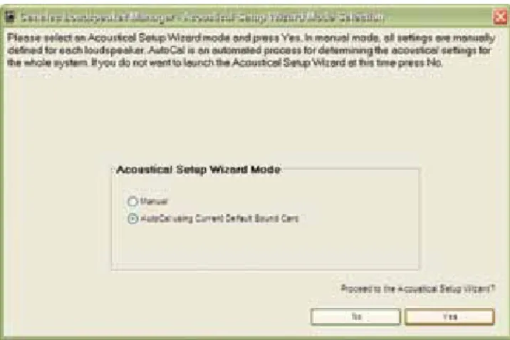
ACOUSTICAL SETUP WIZARD ... 33
Network Interface Device with Sound Card ... 33
Network Interface Device without Sound Card ... 33
AUTOCAL – FULLY AUTOMATED SYSTEM CALIBRATION ... 34
AutoCalTM Theory of Operation ... 34
Setting up for AutoCal ... 34
To set up for AutoCal with Genelec Network Interface / Sound Card ... 34
To set up for AutoCal with Host Computers’s Internal Default Sound Card ... 34
Disabling USB Hub Power Management ... 36
Running AutoCal ... 37
Symmetrical Placement EQ ... 37
Subwoofer Phase Aligment using the AutoPhase ... 38
Level alignment for multiple daisy-chained subwoofers ... 39
Editing AutoCal settings manually ... 39
Storing settings permanently into loudspeakers ... 40
BASIC USE OF THE GLM ... 40
GLM Main Page ... 40
Mute All and Bypass BM ... 40
Volume Control ... 41
Access to the GLM System Setup Editors ... 42
Information Data Banner ... 42
Audio Channel Group Functions ... 42
Menu Items ... 42
MANAGING SYSTEM SETUPS ... 43
Saving and Recalling Setups ... 43
Opening the System Setup Editor ... 44
Editing Audio Cabling Definitions... 44
Editing Group Definitions ... 45
Replacing and Removing Loudspeakers in a System Setup File ... 45
EDITING ACOUSTIC CALIBRATIONS ... 47
Opening the Acoustical Settings Editor ... 47
DSP Loudspeakers ... 47
Room Response Controls ... 48
Interactive Response Editor ... 49
Level and Distance ... 49
Vertical Axis Trim ... 49
Test Signals and Force Input/Solo ... 49
Preview ... 50
Saving and Loading Acoustic Settings ... 50
Storing Acoustic Settings in Loudspeaker Memory ... 50
Saving the settings into a System Setup File ... 50
Subwoofers ... 50
Room Response Controls ... 51
Interactive Response Editor ... 51
Bass Roll-off ... 51
Level and Distance ... 52
Crossover phase alignment ... 52
Crossover Frequency Selections ... 52
Test Signal Generators ... 53
Preview ... 53
Saving and Loading Acoustic Settings ... 53
Storing Acoustic Settings in Subwoofer Memory ... 53
Saving the settings into a System Setup File ... 53
Using the Interactive Response Editor ... 54
STAND-ALONE OPERATION ... 55
DSP Loudspeakers ... 55
Analog Signal Input ... 55
Digital Signal Input ... 55
Front panel warning light ... 55
Back Panel Controls ... 55
Subwoofers ... 56
Digital Signal Input and Output ... 56
Connector Panel Details ... 57
Storing settings in loudspeakers and subwoofers ... 60
Selecting the Stored Settings ... 60
Why use Stored Settings? ... 60
Creating, editing and using Stored Settings ... 60
FUNCTION REFERENCE ... 61
Desktop Compensation ... 61
Genelec AutoCal ... 61
Loudspeakers Online ... 61
Load Setup ... 61
Wizard Introduction ... 62
Rapid Cabling Preset Selection ... 62
Loudspeaker Marking ... 62
System Audio Connections ... 63
Rapid Cabling ... 63
Signal Format ... 63
Analog or Digital Signal Type ... 63
AES/EBU Mode Selection ... 64
Audio Cable Definition ... 64
Audio Cabling Summary ... 65
Loudspeaker Connection ... 65
DSP Subwoofer ... 65
DSP Loudspeaker ... 66
Floating Level Fader ... 66
Reference Level Calibration ... 66
Vertical Axis Trim ... 67
Uninstalling GLM ... 68
Windows ... 68
Macintosh ... 68
Configurable settings for Griffin Powermate knob... 68
GLM AutoLink Application ... 68
Tips for GLM AutoLink use ... 69
Shortcut Keys in the GLM Software ... 73
Keyboard shortcuts in the Windows version of GLM ... 73
Keyboard shortcuts in the Mac version of GLM ... 74
FREQUENTLY ASKED QUESTIONS ... 75
Product ... 75
System Building ... 76
Connectivity ... 77
Software ... 77
INTRODUCTION
Congratulations and thank-you for the purchase of this Genelec DSP Loudspeaker System. These systems are designed to in-tegrate easily into the digital production environment. There are several ways to configure and operate the DSP loudspeakers for a wide variety of high quality audio applications. The DSP loud-speakers have also analog inputs, making them versatile and intelligent replacements for analog loudspeakers.
This manual addresses the Genelec Loudspeaker Manager GLM™ and the proprietary Genelec loudspeaker control net-work, guiding step-by-step through the setup process. The DSP loudspeakers can also be used in stand-alone mode just like any other loudspeaker but without enjoying the benefits of additional flexibility and versatility of the GLM™.
Genelec Loudspeaker Manager (GLM), Genelec AutoCal, Ac-cuSmooth, SinglePoint, Symmetrical Placement EQ, AutoPhase and MultiPoint are trademarks of Genelec Oy.
Parts of the Genelec Loudspeaker Manager are written using MATLAB®. © 1984 -2005 The MathWorks, Inc.
SOFTWARE REGISTRATION AND
UPDATES
Free software registration and updates are available through Genelec’s Community website www.community.genelec.com. All you need to do is to register as a Genelec Community member to access the software download section.
GLOSSARY
.eq1 file
A subwoofer acoustical settings file.
.eq2 file
A two-way loudspeaker acoustical settings file.
.eq3 file
A three-way loudspeaker acoustical settings file.
.gtd file
Genelec Time Data file containing the computed impulse re-sponses of a loudspeaker or subwoofer.
3.5 mm Measurement Signal Cable
A 3.5 mm stereo jack-to-jack interconnection cable used to con-nect the MIC OUT socket on the GLM Network Interface to a computer’s soundcard input.
AccuSmooth
A proprietary smoothing algorithm that has a higher resolution (narrower smoothing bandwidth) at low frequencies than a stan-dard 1/3 octave smoothing, and a similar resolution at high fre-quencies. This is used by AutoCal to ensure accurate placement of notch filters at critical bass frequencies.
Acoustical Settings Editor
A page in the GLM that provides access to the Acoustical Set-tings in the loudspeaker or subwoofer. The Interactive Response Editor can also be accessed here.
Acoustical Setup Wizard
A self-guided Wizard that allows for manual or automated (Auto-Cal) calibration of the Loudspeaker Acoustic parameters.
Analog Signal Cable
The GLM supports AES/EBU digital audio cables and analog audio cables. An analog audio cable carries one channel of audio. An AES/EBU cable can carry one or two channels of audio.
Audio channel
Although the definition of an audio channel is rather straightfor-ward and clear, it should not be confused with loudspeakers or audio cables in the loudspeaker system. The AES/EBU digital audio cables may carry one or two audio channels. There may be one or more loudspeakers reproducing one audio channel.
Bass Management
Bass Management is used to reproduce the low frequency con-tent of audio channels over one or more subwoofers instead of loudspeakers. This can be the low frequency content from the full-bandwidth audio channels. Parts or the entire LFE audio channel can also be bass managed.
Digital Signal Cable
The digital signal cable carries an AES/EBU audio signal. The GLM supports AES/EBU digital audio cables and analog audio cables. An AES/EBU cable can carry one or two channels of au-dio.
Digital Thru
The connector on the back of a loudspeaker used to pass the AES/EBU digital audio signal presented to the digital input con-nector onto another loudspeaker.
Genelec 8200A Calibration Microphone
A factory calibrated acoustic measurement microphone used for AutoCal system alignment.
Genelec AutoCal
Genelec AutoCal is a property of the GLM software that uti-lizes built-in test signal generators inside all Genelec DSP loud-speakers to acoustically measure and align the loudspeaker system.
Genelec AutoPhase
Genelec AutoPhase is a part of Genelec AutoCal. It aligns the phase of the subwoofer(s) in the system to the designated loudspeaker(s).
GLM AutoLink
A user-definable program that allows operators to launch GLM with a specific Setup automatically loaded.
GLM Control Network
The GLM loudspeaker control network is a proprietary network allowing the setting, reading and monitoring of loudspeakers and subwoofers on the GLM network. System setup can be achieved very rapidly by simply opening a System Setup file, which causes all system and loudspeaker settings to be automatically commu-nicated to all loudspeakers.
GLM DSP Loudspeaker Manager Package
The GLM control network delivery package containing all hard-ware and softhard-ware to build a GLM Loudspeaker Manager environ-ment. Loudspeakers and subwoofers are purchased separately.
GLM DSP Multiroom Expansion Package
An expansion package providing a license and hardware to in-stall the GLM in multiple rooms within a single facility.
GLM Main Page
The face of the GLM. This page is used to access all other func-tions of Loudspeaker Manager.
GLM Network Interface
The GLM Network Interface is a USB device that connects the computer to the GLM loudspeaker control network. The GLM Network Interface translates communication between the com-puter and the control network, enabling a very large and physi-cally long control network with multiple loudspeakers. The GLM Network Interface isolates the private and confidential messag-ing with loudspeakers from any public data networks and from the functioning of the computer running the GLM software. The GLM Network Interface also incorporates a built-in microphone pre-amplifier as well as a high quality soundcard for use during the AutoCal procedure.
GLM System Setup Editor
This page is used to access more detailed sections of the GLM including the Acoustical Settings Editor.
GLM Software
GLM is an abbreviation for the Genelec Loudspeaker Manager. This software enables setup and control of loudspeakers on the GLM control network through the use of system setup files, and supports fully automated loudspeaker system setup.
Global High Frequencies Tilt Selections
Setup menu function that opens a selection of five preset HF tilt settings
Group
Loudspeakers or audio channels designated to play simultane-ously.
ID Tone
A built-in tone in the DSP loudspeakers and subwoofers used to identify which loudspeaker is being adressed.
IEC Mains Cable
A standard detachable mains cable used to apply mains electri-cal power to the loudspeaker or subwoofer.
Interactive Response Editor
Located in the Acoustical Settings Editor, this Editor allows for the interactive adjustment of a measured response using the Room Response Controls.
Loudspeaker
This term is used for loudspeakers that are not subwoofers. A 8240A, 8250A, 8260A or 1238CF active DSP loudspeaker.
Manual Acoustic Wizard
A self-guided Wizard that allows for manual calibration of the loudspeaker acoustic parameters.
Manual Cabling Wizard
A self-guided Wizard that allows for more complicated and versa-tile System Setups not found in the Rapid Cabling Wizard.
Manual Controls
The user interface settings on a loudspeaker or subwoofer used when in stand-alone mode.
Microphone Holder
The rubber mounting hardware to attach the Genelec 8200A Calibration Microphone to a standard microphone stand.
MultiPoint
A method of spatial averaging used in AutoCal measurements, used when optimizing the Acoustical Settings.
Network Cable
A CAT5 cable with RJ45 connectors (type PC-to-HUB, straight not crossed wiring). This cable is also used as an Ethernet net-work cable. Netnet-work cables connects the GLM Netnet-work Interface to the loudspeakers and subwoofers to form a network of devices that may be controlled using the GLM software
Network Control Mode
The use of Genelec DSP loudspeakers with the GLM software and the control network.
NID
Node
Every loudspeaker and the GLM Network Interface is a node on the GLM control network.
Rapid Cabling Wizard
The GLM contains pre-made system setups of the most typical loudspeaker arrangements. Rapid Cabling makes system setup simple and fast by allows the selection of one of these presets.
Room Response Controls
A collection of controls used to modify the loudspeaker or sub-woofer response in order to improve the in-room sound quality at the listening position.
SinglePoint
A measurement taken in the main monitoring position used by AutoCal when optimizing the Acoustical Settings.
Software CD
The CD-ROM containing the install files for Genelec Loudspeak-er ManagLoudspeak-er and AutoCal.
Stand-Alone Mode
The use of Genelec DSP loudspeakers as individual loud-speak-ers, without the GLM software and the control network.
Stored Settings
The settings stored inside a loudspeaker or subwoofer. These settings are used when the loudspeaker is operated in the stand alone mode.
Subwoofer
A 7260A, 7270A or 7271A active DSP subwoofer with 8 channel bass management.
System Setup File
Files stored on the hard drive of a computer running the GLM. Loading a System Setup File in GLM automatically sets up all loudspeakers in the system with stored monitoring Group defini-tions, audio cable definidefini-tions, defaults for monitoring levels and all acoustical alignment settings.
System Setup Wizard
System Setup Wizard guides the user through the process of setting up the GLM.
Third-party Volume Controller
A peripheral device (e.g. Griffin PowerMate or Contour Design ShuttleXpress) used to control the system volume.
USB Cable
A type A-B USB cable used to connect the GLM Network Inter-face to a computer.
SYSTEM PARTS
The Genelec DSP loudspeaker system consists of • DSP loudspeakers
• DSP Subwoofers
• GLM DSP Loudspeaker Manager Package containing the user interface software with the GLM Control Network Inter-face and a factory calibrated acoustic measurement micro-phone for controlling DSP loudspeakers
• GLM DSP Multiroom Expansion Package
A basic working system requires only loudspeaker(s). See Get-ting Started.
Loudspeaker Delivery Content
• Loudspeaker • IEC Mains Cable • Network Cable
• Loudspeaker Operating Manual
Subwoofer Delivery Content
• Subwoofer • IEC Mains Cable • Network Cable
• Subwoofer Operating Manual
GLM DSP Loudspeaker Manager Package
Delivery Content
The GLM™ Genelec Loudspeaker Manager is a loudspeaker con-trol networking system that offers capability to concon-trol all system parameters as well as the possibility for detailed acoustical align-ment of every loudspeaker in the system. The use of the GLM is warmly recommended. Genelec AutoCal™ provides the GLM with a fully automated multi-loudspeaker system acoustical calibra-tion capability and comes with a factory-calibrated measurement grade microphone, microphone amplifier and microphone holder.
This document refers to GLM software version 1.4. compatible with models 8240A, 8250A, 8260A, 1238CF, 7260A, 7270A and 7271A. Updates of the software are available through Genelec Community website www.community.genelec.com. Registration and membership of the Community is free.
Contents of the GLM delivery box • Software CD
• Genelec DSP Loudspeaker System Operating Manual • Quick Connection Guide
• GLM Network Interface with integrated Genelec sound card and microphone preamplifier
• USB Cable
• Genelec 8200A Measurement Microphone • Microphone Holder
• Measurement Signal Cable with 3.5 mm stereo plugs
GLM DSP Multiroom Expansion Package
Delivery Content
The GLM software is sold with a site-license permitting instal-lation into multiple rooms. The GLM DSP Multiroom Expansion Package delivers a GLM Network Interface and cables for instal-lation into one additional room. Each additional room needs a multiroom expansion pack.
• GLM Network Interface with integrated Genelec sound card and microphone preamplifier
• USB Cable
LOUDSPEAKERS
This section provides a rapid overview of Genelec DSP loud-speakers. In-depth information about the DSP loudspeakers is available at www.genelec.com and in the Operating Manuals supplied with the DSP loudspeakers.
DSP Loudspeakers
The DSP loudspeakers accept both AES/EBU digital audio and analog audio.
Analog input
The analog input on Genelec loudspeakers has a fixed sensitiv-ity. A 0 dBu (0.775 volts) signal produces a 94 dB SPL at 1 m. The maximum sound pressure level depends on the loudspeak-er model. A largloudspeak-er loudspeakloudspeak-er will produce a highloudspeak-er maximum sound pressure level than a smaller one.
Digital audio input
The digital input has a fixed sensitivity. Digital signals are repre-sented relative to their maximum value, or Full Scale (FS) value. For example, -10 dBFS means that the digital audio signal level is 10 dB below the full scale or the maximum representable digi-tal signal.
In Genelec DSP loudspeakers, the maximum theoretical audio level for a 0 dBFS digital audio input signal translates to 130 dB SPL at 1 m sound pressure level. For example, a signal having -36 dBFS level produces a sound level of 94 dB SPL at 1 m. This is a technical specification of the loudspeaker, and the Genelec Loudspeaker Manager GLM can adjust the monitoring volume down from this level.
Digital audio sample rate can vary from 32 kHz to 192 kHz and word length from 16 to 24 bits. Single-Wire and Dual-Wire sig-nals are automatically detected
Digital audio takes precedence over analog audio. If a valid AES/ EBU signal is presented to the loudspeaker, that input will be selected and the analog audio will mute. Note that there may be
a valid AES/EBU signal although the signal is silent. However, in the computer controlled mode of operation, GLM Setups can specifically activate the analog inputs even if a valid bitstream is detected.
Loudspeaker Functional Blocks
All audio enters the DSP processor, where all signal process-ing and filterprocess-ing takes place. The audio outputs go via digital-to-analog conversion to built-in power amplifiers and on to the tweeter and woofer drivers. The loudspeakers have built-in user interfaces with switches and a rotary level control in the rear of the loudspeaker, as well as a connection for the Genelec Loud-speaker Manager network enabling centralized management of up to 30 loudspeakers in one installation.
DSP Subwoofers
Digital audio input
The digital input has a fixed sensitivity. Digital signals are rep-resented relative to their maximum or Full Scale value. For ex-ample, -10 dBFS means that the signal level is 10 dB below the full scale or the maximum representable digital signal.
In Genelec DSP subwoofers, the maximum audio level of 0 dBFS translates to the theoretical 130 dB SPL at 1 m sound pressure level. For example, a -36 dBFS signal produces a sound level of 94 dB SPL at 1 m. Genelec Loudspeaker Manager GLM adjusts the monitoring volume down from this level.
Digital audio sample rates can vary from 32 kHz to 192 kHz and word length from 16 to 24 bits. Single-Wire and Dual-Wire signals are automatically detected. Note that there may be a valid AES/ EBU signal although the signal is silent.
Subwoofer functional blocks
The subwoofers have AES/EBU digital audio inputs only. There are no analog audio inputs. All audio enters the DSP processor, where all signal processing takes place. The output goes via
digital-to-PLACING LOUDSPEAKERS IN THE
MONITORING ROOM
Here is a quick introduction to monitoring loudspeaker placement.
• Place the loudspeakers in their expected positions before ca-bling anything.
• Attempt to place all loudspeakers at ear height for the person in the primary listening position. If a loudspeaker is higher than ear height, tilt and turn the loudspeaker toward the lis-tening position. Genelec 8200 Series loudspeakers feature a vibration-isolating monitor stand, the IsoPod™, which en-ables the positioning of the loudspeaker towards to the pri-mary listening position.
• Aim the acoustic axis of all loudspeakers towards the main listening position both horizontally (turn towards the listening position) and vertically (tilt towards the listening position). • Position subwoofer(s) close to the wall(s).
• If a subwoofer is used, remember that all audio cables must go to the subwoofer first and then to the loudspeakers. Make sure that enough cable length is available to move the subwoofer around the room to find a location of optimal performance. Figure 1. Functional blocks of a two-way DSP loudspeaker
Figure 2. Functional blocks of a DSP subwoofer
analog conversion to the built-in power amplifier and driver(s). The subwoofers have a built-in user interface with switches and rotary controls and a connection to the Genelec Loudspeaker Manager network enabling centralized management of up to 30 loudspeak-ers including subwoofloudspeak-ers in one installation.
Full-bandwidth loudspeaker placement
Minimum distance from a wall behind a loudspeaker
Genelec DSP loudspeakers should be placed so that a minimum distance of 5 cm (2”) is left behind the loudspeaker for amplifier cooling and rear opening reflex port sound radiation.
Low frequency cancellations
In general, when a loudspeaker’s front baffle is more than 0,3 meters (1 foot) away from the wall behind the loudspeaker, a re-flection from this wall can cause a cancellation of low frequencies and hence reduction of bass output. For the DSP loudspeakers, low frequency cancellations in the 40 – 80 Hz frequency range should be avoided. Cancellations in the 80 - 200 Hz range should also be avoided if possible.
Recommended distances
Translating this into distance recommendations shows that loud-speakers can be placed close to a wall (see above) at a distance less than 1 meter (3 ft.). Distances between 1 and 2.2 meters (3-7 ft.) should be avoided.
Loudspeakers placed more than 2.2 meters (7 ft.) away from walls may suffer from cancellations around the low frequency cut-off of the loudspeaker limiting low frequency bandwidth. As a rule of thumb, the lower the low frequency cut-off the further away the loudspeaker must be placed from the wall in order to avoid this phenomenon.
Distances to the ceiling and other walls may be shorter than the distance to the wall behind a loudspeaker. Reflections from these surfaces may be important and should also be considered.
Subwoofer placement
Subwoofers can make life much easier in producing high qual-ity low frequency reproduction. When a subwoofer is used, the loudspeakers can be placed more freely, thereby allowing more flexibility in finding a good location in the room for the reproduc-tion of low frequencies.
A subwoofer should be placed close to a wall, preferably closer than 0.6 meters (2 ft.) from a wall. This eliminates most possible cancellation sources and the subwoofer response remains flat and well loaded.
Using a subwoofer provides an additional crossover frequency (typically at 85 Hz). This makes placing loudspeakers much eas-ier. Acceptable distances extend to 1.1 m because of the low frequency cut-off of loudspeakers. Loudspeakers may be placed 1.1…2 m without serious compromises due to the wall behind the loudspeaker causing serious cancellation effects.
Although Genelec subwoofers provide accurate phase control at the crossover point, loudspeakers should not be placed further than 2 m (7 ft.) from a supporting subwoofer. Larger distance dif-ferences may cause tonal balance difdif-ferences around the cross-over frequencies due to loudspeakers and subwoofer(s) exciting different room modes.
Multi-channel System Layout
The positioning of tables, screens, racks, etc, is critical in order to maintain accurate imaging. Early reflections can smear the sound image and compromise localization. To avoid this, reflect-ing surfaces between loudspeakers and the listenreflect-ing position should be minimized. Symmetrical positioning of equipment is essential. Even with symmetry, reflecting surfaces should be re-moved from the vicinity of acoustic paths.
Figure 3. Recommended distances from a single wall to the front baffle of free-standing loudspeakers. Correct (green), ac-ceptable (orange) and not recommended (red).
Figure 4. Recommended distances from a single wall to the front baffle of loudspeakers combined with subwoofer(s). Cor-rect (green), acceptable (orange) and not recommended (red).
Front loudspeaker, multi-channel layout.
For multi-channel audio the Left and Right loudspeakers should be placed 60 degrees apart, with the Center loudspeaker in the middle. All loudspeakers should be of the same type so there are no coloration changes when panning sounds across the front stage.
Recommended loudspeaker positioning
for 5.1 multi-channel audio reproduction
Surround loudspeakers
Surround loudspeakers should be placed in a positional window between ±100 to ±120 degrees from the centerline. If more than two loudspeakers are used an equal number of loudspeakers should be placed symmetrically on both sides of the center line, on a circle between ±60 to ±150 degrees. Most recording engi-neers choose ±110…130-degree position for a surround stereo pair.
System location in room
It is important that the multi-channel installation is symmetrically located in the room. Reflections created by boundaries should be identical from left to right so that spatial information and pan-ning of sources remains stable. It is also recommended that the listening position be located in the front half of the room so that the direct sound level is maximized relative to the reverberant energy in the room.
Aiming of acoustical axes
All loudspeakers should be aimed towards the engineer’s listen-ing position.
Figure 5. Example of non-symmetrical layout producing reflec-tions from computer screens and table surface totally different for different loudspeakers. This situation creates front-back and left-right localisation smearing.
Figure 6. Symmetrical layout minimizes reflection surfaces and maintains accurate localisation because reflections are similar due to symmetry.
Figure 7. Recommended loudspeaker positioning in a 5.1 chan-nel system. .
GETTING STARTED
Quick course to system basics
Control network and audio cabling are separate
The first observation to be made is that audio signals and control information travel along different cables. This has the inherent advantage of allowing one to operate the system with the control network (known as the network control mode) or without the con-trol network if so desired (known as the stand-alone mode).
When using the Genelec loudspeaker control network, full con-trol to all features in a loudspeaker become available. Attaching the control network automatically puts the loudspeaker in the network-controlled mode.
Digital audio
All Genelec DSP loudspeakers and subwoofers have AES/EBU digital audio inputs. When applicable, run the AES/EBU audio
cable(s) to the subwoofer first, then onto the main loudspeakers. If the AES/EBU cable carries two digital audio channels, run an-other cable from the “Thru” output of the loudspeaker to the input of the next loudspeaker.
If the audio source has a volume control for the AES/EBU digital audio, it can be used to control the monitoring level.
If the AES/EBU outputs are fixed level line-outs, various volume controls options are available in the GLM loudspeaker control software.
The GLM software provides several volume control faders on the computer display. These volume controls can be used in the same computer running audio processing or recording software.
Third-party volume control knobs (for example Griffin Power-Mate) that attach to a USB interface can also be used to control the monitoring level through the GLM software and the Genelec loudspeaker control network.
Loudspeakers
DIGITAL AUDIO
DIGITAL VOLUME CONTROL
1 2
3
You can control the Volume from 3 different locations.
GLM CONTROL NETWORK
Digital Audio Source
USB CONTROLLER
Subwoofer
Loudspeakers
DIGITAL AUDIO THRU
OUT
DIGITAL AUDIO THRU
OUT GLMTM
Figure 8. Routing of the digital audio signal. If a subwoofer is used, all channels should be routed through it first. Two daisy-chained DSP loudspeakers reproducing a two-channel AES/EBU signal are connected to one of the subwoofers output connector.
Figure 9. Connecting the GLM control network (green line). The control network links all loudspeakers and subwoofers to one daisy-chain, connected to a computer via the GLM control network interface. Optional USB volume control also shown.
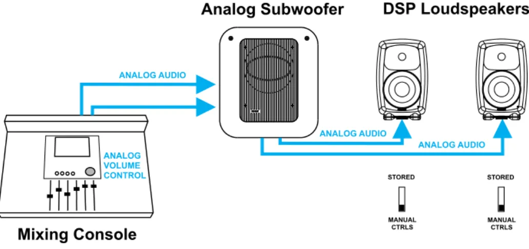
Analog audio
The DSP loudspeakers have an analog audio input and can be connected just like any other (analog) loudspeaker. They can be used with analog subwoofers and mixed with analog loudspeak-ers to build a system. It is easy to achieve good system integra-tion as the input sensitivity of the DSP loudspeakers is the same as that of the analog loudspeakers.
Cabling works just like any other analog loudspeaker setup. The analog audio cables are first connected to a Genelec subwoofer where bass management takes place, and then onwards to the loudspeakers.
Stand-alone mode refers to using DSP loudspeakers without the GLM Control Network.
The DSP loudspeakers are equipped with both analog and digital inputs, and digital audio takes precedence over analog audio. In stand-alone mode the analog input works only if there is no AES/ EBU digital audio input to the loudspeaker, for example when the
digital cable is removed or the AES/EBU bit stream is halted at the source.
When using the GLM loudspeaker system control software, it is possible to select between analog and digital inputs. Analog and digital signals are never mixed.
When calibrating the DSP loudspeakers one can select to use the same switch-based acoustic alignments that can be found on the analog loudspeakers, or to use a much more versatile set of room response controls available through the GLM loudspeaker control software and the Genelec loudspeaker control network link built into all DSP loudspeakers.
The GLM software runs on any Windows XP, Vista or Macintosh OSX computer. The GLM Network Interface connects the com-puter to the loudspeakers. Using the GLM software provides full access to all room response controls. After aligning the loud-speakers acoustically, it is possible to store these settings inside the loudspeaker’s memory.
STORED
MANUAL CTRLS
ANALOG VOLUME CONTROL
Mixing Console
ANALOG AUDIO
Analog Subwoofer
DSP Loudspeakers
STORED
MANUAL CTRLS
ANALOG AUDIO
ANALOG AUDIO
GLM
TMLoudspeakers
GLM CONTROL NETWORK
Figure 10. Connecting the DSP loudspeakers to an analog signal source and analog subwoofer independent of a GLM network. Manual Controls (the DIP switches on the loudspeaker’s back panels) activated.
Step-by-step system setup for GLM
Control Network use
The Genelec DSP loudspeaker family uses a networking concept for controlling a system of loudspeakers. A control network cable is provided with all Genelec DSP loudspeaker products. To setup quickly, follow the steps detailed below. For further information consult the sections of this manual mentioned in each step.
• Unpack and position the loudspeakers. See the “Loudspeak-er Placement” section for details.
• Find the Genelec Control Network cables in each loudspeak-er delivloudspeak-ery box. Connect the control network. See the “Genel-ec control network cabling” s“Genel-ection for details.
• Find the GLM Network Interface and follow cabling instruc-tions.
• Find the software CD in the Genelec Loudspeaker Manager package, insert it in computer and follow on-screen instruc-tions to install Genelec Loudspeaker Manager GLM on the computer.
• See the “GLM Genelec Loudspeaker Manager” section for details.
• Label and connect the audio cables. See the “Audio Cabling” section for details.
• Launch GLM, then follow the on-screen instructions to com-plete a System Setup. Select either Rapid Cabling Mode or Manual Cabling Mode and follow the instructions.
• Select the appropriate Rapid Cabling preset in the GLM and launch the Rapid Cabling Wizard.
• See the “Rapid Audio Cabling” section for details.
• To acoustically align the system, run the Acoustic Setup Wiz-ard in the GLM. See the “Acoustic Setup WizWiz-ard” section for details.
• Congratulations! Setup is now complete!
A more detailed system setup procedure can be found in the sec-tion describing the System Setup Wizard.
Step-by-step system setup for
Stand-Alone use
Stand-alone use
Genelec DSP loudspeakers can be used like any other loud-speaker system, without the GLM control network. This is known as stand-alone use.
• Note that when a DSP loudspeaker detects a valid AES/EBU word clock, the system will sync and run in the digital input mode.
• DSP subwoofers only have digital audio inputs and can be used in stand-alone mode running AES/EBU-digital audio. • When DSP loudspeakers are used as analog loudspeakers,
analog subwoofers can be used.
• All Genelec DSP loudspeakers feature a user interface with switches and a rotary level control. These are used for stand-alone operation.
• For more information on setting up and using loudspeakers in stand-alone mode, see the section on stand-alone opera-tion.
GENELEC LOUDSPEAKER
MANAGER GLM
Overview
The Genelec Loudspeaker Manager GLM is the control software for Genelec DSP loudspeaker systems. The GLM runs on a per-sonal computer.
The GLM knows which DSP loudspeakers are present on the control network and provides access to all loudspeaker settings and system level controls.
The GLM is capable of controlling a combination of up to 30 main loudspeakers and subwoofers and offers control of every-thing within the loudspeaker system. This includes controls built into individual speakers as well as full system controls including monitoring volume, mute/solo for audio channels, audio channel Group selection and more.
All settings can be collectively stored into the computer as a Sys-tem Setup File. Loading a SysSys-tem Setup File recalls all sysSys-tem level settings and sets all settings inside each loudspeaker, in-cluding acoustic calibration.
Using the GLM, all acoustic settings can also be stored into each loudspeaker for stand-alone use.
The basic structure of a GLM Control Network has the following components
• Computer running the GLM software.
• One USB port of the computer connected to the GLM Net-work Interface.
• The GLM Network Interface.
• Network cable connected to all loudspeakers on the control network.
GLM Control Network
GLM Network Interface
The GLM Network Interface serves as the communicator be-tween all loudspeakers on the control network and the computer. Attach the GLM Network Interface to a USB port. The device driver is installed automatically.
The USB cable runs from the computer to the GLM Network Inter-face. Once the GLM Network Interface is connected to the comput-er flashing lights on the intcomput-erface indicate that the network is active. If no lights are flashing, check that the control network and USB cables are securely attached and the GLM software is running.
The control network runs on CAT5 cables. These are the same cables that are used for Ethernet. Instead of using Ethernet for communication with loudspeakers, Genelec uses a proprietary protocol defining the method of communication, and the GLM Net-work Interface that connects to the USB port on the computer.
There are several important reasons why a USB interface is used instead of, for example, the Ethernet. This keeps the network run-ning at all times, even if the computer crashes. The GLM Network Interface acts as the master controller on the network, and com-municates to all loudspeakers even if the computer is rebooting.
The Genelec network uses a proprietary communication protocol to ensure integrity of communication to and from loudspeakers. The GLM Network Interface is used as a translator between the Genelec control network and any computer hardware using it. This ensures that loudspeaker control traffic remains insulated and secured from any public networks. This is necessary be-cause of the possibility of congestion on public networks (loud-speaker control messages do not get through), and in order to limit the range of access (outsiders on a public network could possibly control the loudspeakers).
A USB cable run is normally limited to 5 m (15 ft.), but this is not a problem. The control network cable from the GLM Network In-terface can extend to any practical distance. If the GLM Network Interface cannot be placed close the computer the USB cable can be extended with actively buffered cables up to 25 meters (75 ft.) in length.
Note
If the GLM Network Interface is disconnected or the computer is powered down, the GLM will no longer control the loudspeakers. In that event, the loudspeakers maintain their current settings until the loudspeaker is powered down.
When the loudspeakers are re-powered and the GLM software is not controlling the network, the loudspeakers obtain acoustic settings based either on the user interface controls on the loud-speaker (manual controls) or from their internal memory (stored settings). This choice is determined by the position of switch marked “STORED/MANUAL CTRL”.
GLM Control Network Cabling
Control comes from the computer running the GLM software. The computer connects to the GLM Network Interface via the USB port (a 1.5-meter USB cable is provided). The GLM Network Inter-face connects onwards to all loudspeakers using network cable.
The GLM Control Network starts from the GLM Network Interface and connects to the first loudspeaker (any one, just take a pick) and then onwards until all loudspeakers have been connected.
Each loudspeaker has two control network connections. One is used as the input and the other as the output to the next loud-speaker. It does not matter in which order the loudspeakers are connected on the GLM Control Network. On the last loudspeaker of the control network chain, only one of the two Genelec control network connectors will be used.
Consider an example with five loudspeakers and one subwoofer. The digital audio uses AES/EBU cabling where each physical audio cable carry two channels of digital audio. All audio cables run to the subwoofer first and then to the loudspeakers. The GLM Control Network starts from the USB port of the system-controlling computer, runs through the GLM Network Interface and onwards to all loudspeakers. Because the order in which loudspeakers are connected to the control network is free and arbitrary, the control network cable was run conveniently in this example to two loudspeakers, then to the subwoofer and finally to the remaining three loudspeakers.
Figure 13. Daisy-chaining the loudspeakers with the GLM control network.
Figure 14. GLM control network (green) and signal cabling in a 5.1 channel system
GLM Control Network Size
Number of loudspeakers
The GLM Control Network can support up to 30 loudspeakers. All loudspeakers should be in one room.
Control network length
The length of the GLM Control Network is calculated by adding up the entire control network cable in the system. For example, six runs of 10-meter cables, gives a total cable length of 60 me-ters (180 ft.). If the total length of the network cable exceeds 300 meters (900 feet), contact the local Genelec Distributor for solutions.
All Genelec DSP loudspeakers are supplied with one 5 m net-work cable. Additional or longer standard high quality CAT5 Eth-ernet cable with PC-to-HUB (direct) wiring, can be purchased from a local computer store. This is the normal wiring for a CAT5 cable. Note that the cable must be fully populated, that is, the cable must have all eight pins in the connectors connected by wires.
Installing the GLM Software
Windows
• Insert the software CD in the CD-ROM drive. The installation application will be opened automatically
• (If autorun is disabled then Install.exe file must be manually launched from the CD).
• Click ‘Install GLM software’ to launch the installation. • Follow the instructions.
• To finish the installation the system needs to be restarted.
Macintosh
• Open GLM CD with Finder.
• Select the software version that matches the OS X version to be used on the GLM computer, and launch that package. • Follow the instructions.
• To finish the installation the system will be restarted.
Note
Macintosh installation package will always install X11 application from the CD. If X11 application already exists in the system, use customized installation type to remove X11 from the installation task.
Running the System Setup Wizard
The System Setup Wizard is a self-guiding program designed to make the installation process easy and complete. The ba-sic flow of setting up the system is detailed below. Consult the sections of this manual mentioned in each step for further details.
• Unpack and position the loudspeakers. See the “Loudspeak-er Placement” section for details.
• Find the Genelec Control Network cables in each loudspeak-er delivloudspeak-ery box. Connect the control network. See the “Genel-ec control network cabling” s“Genel-ection for details.
• Find the GLM Network Interface Device and follow cabling instructions. See the “GLM Network Interface Device” section for details.
• Find the software CD in the Genelec Loudspeaker Manager package, insert it in computer and follow on-screen instruc-tions to install Genelec Loudspeaker Manager GLM on the computer. See the “GLM Genelec Loudspeaker Manager” section for details.
• Label and connect the audio cables. See the “Audio Cabling” section for details.
• Launch the GLM, then follow the on-screen instructions to complete a System Setup. Select either Rapid Cabling Mode or Manual Cabling Mode and follow the instructions.
• If there is no applicable Rapid Cabling Preset, select the Man-ual Cabling Wizard. See the “ManMan-ual Audio Cabling” section for details. Plan all cabling according to the guidelines pro-vided in this section. Plan channel labeling and loudspeaker labeling and launch the Manual Cabling Wizard.
• To acoustically align the system, run the Acoustic Setup Wiz-ard in the GLM. See the “Acoustic Setup WizWiz-ard” section for details.
• Use the fully automated alignment system AutoCal built into the Acoustic Setup Wizard.
• Finally Save the System Setup and study the basic use of the GLM.
Before running the System Setup Wizard, make sure that all au-dio source equipment output levels are turned down.
Once the network cabling is complete, turn on all the loudspeak-ers. From the computer, launch the Genelec Loudspeaker Man-ager by clicking on the Genelec Loudspeaker ManMan-ager icon.
Launching the GLM for the first time automatically starts the System Setup Wizard. The first screen that appears is the Loud-speakers Online counter. Check that the number of loudLoud-speakers and subwoofers displayed in the GLM is the same as the number of loudspeakers and subwoofers connected to the GLM Control Network. If the numbers do not match, check the network cables and connections, and the mains power to the loudspeakers and subwoofers.
Click “Next>” to Continue.
An introduction to the GLM System Setup Wizard will be pre-sented first. Click “Run System Setup Wizard“ to start the GLM System Setup Wizard.
AUDIO CABLING
Always plan your audio cabling and label the cables before con-necting them and running the System Setup Wizard. It is suggest-ed that the digital audio cables are labellsuggest-ed using the following convention: “AES/EBU Channel number and Sub-frame – Loud-speaker location.“ For example: “AES/EBU 1A – Front Left” . Ana-log cables should be labeled using a similar convention.
XLR connector pin assignments for
analog signals
For analog applications, use high quality balanced twisted pair cable with a shield. Use XLR connectors, where pin number one is connected to the shield of the cable, pin number two is desig-nated as the in-phase signal (commonly marked as +) of the ana-log interface, and pin number three is the inverted signal (typically marked by -). This is sometimes known as a “pin 2 hot mic cable.”
XLR connector pin Cable Note
1 Shield Connect at both ends to the cable shield
2 Twisted pair wire 1 In-phase signal 3 Twisted pair wire 2 Inverted signal
XLR connector pin assignments for
AES/EBU signals
For digital applications cables specifically designed to carry high-speed digital audio should be used. This cable should have 110-ohm characteristic impedance. Do not use standard microphone cable as described above. It is well known that microphone ca-bles intended for analog signals do not have good performance for digital audio applications. Using these could result in poor digital audio performance, especially for longer cable runs. The audio format used on these cables is AES/EBU.
The inputs will sync for sample rates from 32 kHz to 192 kHz Single-Wire signals. The inputs will also sync to 192 kHz Dual-Wire signals. Since AES/EBU audio is typically transmitted in audio channel pairs (Channel A and B), connections will have to be made from one loudspeaker to another. This is accomplished via the THRU connector on the back of the loudspeakers and the output connectors in DSP subwoofers. Typical pairing in a two-channel stereo AES/EBU bit-stream has the Left audio two-channel carried in the AES/EBU subframe A and Right audio channel carried in the AES/EBU subframe B. The digital audio cable can go to either loudspeaker first. Select which subframe to repro-duce by selecting Channel A or B in the GLM software or, in case of stand-alone use, on the back panel of the loudspeaker.
MAKE SURE ALL AUDIO CABLES ARE LABELED BEFORE STARTING THE CABLING PROCEDURE!
Figure 15. System Setup Wizard Loudspeakers Online counter screen
Figure 16. System Setup Wizard introduction screen
Figure 17. System Setup Wizard Cabling Wizard selection screen
Stereo Setups
Digital audio cabling carrying two channels can go from source to either loudspeaker first, then on to the next loudspeaker using the THRU connector.
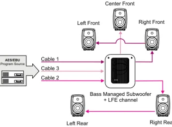
5.1 Multi-Channel Setup
A 5.1 multi-channel setup carries six channels of audio. They are the Left Front, Right Front, Center Front, Left Rear, Right Rear, and LFE channels. The LFE channel is a bandwidth-limited low
frequency effects channel. To reproduce such a 5.1 setup, one subwoofer and five loudspeakers are normally used.
All digital audio cables must run to the subwoofer first. The DSP subwoofers use AES/EBU input number four as the LFE input.
Duplicating Loudspeakers
It is also possible to daisy-chain digital audio signals to addition-al loudspeakers. One such application might be a movie mixing room where multiple loudspeakers must reproduce the rear and side channel signals.
In the example below the Left Rear and Right Rear loudspeakers have been duplicated. The system is built simply by daisy-chain-ing the AES/EBU cable out from one loudspeaker to the next unit until all loudspeakers have been connected. The GLM is then used to assign the correct audio channels to each loudspeaker and to acoustically align the loudspeakers.
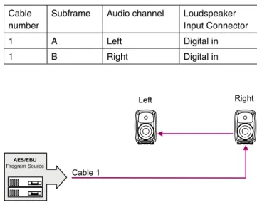
Figure 18. Connecting AES/EBU two-channel cable named “Cable 1”
When using a DSP subwoofer, all wiring MUST go to the sub-woofer first, then to the pair(s) of loudspeakers.
Figure 19. Connecting AES/EBU two-channel cable named “Cable 1” in a stereo system with subwoofer
Figure 20. Connecting three AES/EBU two-channel cables in a 5.1 channel system
Figure 21. Connecting a 5.1 channel system with duplicated rear loudspeakers
Grouping
Some applications might need two sets of left and right loud-speakers, say a pair of 8240A’s as near field monitors and a pair of 8250A’s in a mid-field position. Here, the engineer can use the Grouping functions in the GLM to create Groups for quick selec-tion between the different sets of loudspeakers.
Run an AES/EBU audio cable from the audio source first to the subwoofer(s) and then to the loudspeakers. Using the GLM soft-ware, assign the correct audio channels to each loudspeaker. Then create Group Definitions containing the nearfields with or without
the subwoofer(s) and the midfields with or without the subwoofer(s). The GLM then supports rapid switching between Groups.
The subwoofer should be the first loudspeaker in the chain for those loudspeakers requiring bass-management.
In the example on the right, the 8250A stereo pair is playing full-bandwidth audio only. The subwoofer is placed in the audio ca-bling daisy-chain before the 8240As to enable the 8240As to be bass managed. The subwoofer reproduces low frequencies for the 8240As.
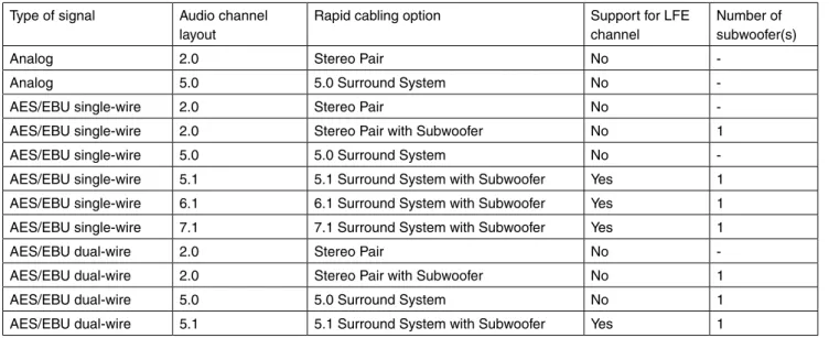
Type of signal Audio channel layout
Rapid cabling option Support for LFE channel
Number of subwoofer(s)
Analog 2.0 Stereo Pair No
-Analog 5.0 5.0 Surround System No -AES/EBU single-wire 2.0 Stereo Pair No -AES/EBU single-wire 2.0 Stereo Pair with Subwoofer No 1 AES/EBU single-wire 5.0 5.0 Surround System No -AES/EBU single-wire 5.1 5.1 Surround System with Subwoofer Yes 1 AES/EBU single-wire 6.1 6.1 Surround System with Subwoofer Yes 1 AES/EBU single-wire 7.1 7.1 Surround System with Subwoofer Yes 1 AES/EBU dual-wire 2.0 Stereo Pair No -AES/EBU dual-wire 2.0 Stereo Pair with Subwoofer No 1 AES/EBU dual-wire 5.0 5.0 Surround System No 1 AES/EBU dual-wire 5.1 5.1 Surround System with Subwoofer Yes 1
GLM
TMRapid Cabling Presets
The Rapid Cabling Presets help speed up the System Setup by quick identification of the speakers and reduced text entries. The most common loudspeaker setups seen in listening rooms have been included with the Rapid Cabling Presets.
Table of Rapid Cabling Presets
Here is a brief list of instructions on how to complete the Rapid Cabling Wizard.
• Before starting the GLM, identify in the Rapid Cabling Preset Table shown above, the description that matches the desired loudspeaker setup. Then, find the corresponding section be-low and study the cabling layout description and the AES subframe assignment table.
• At the sound source (mixing console, audio workstation, etc.) assign audio signals to the AES/EBU outputs according to the table provided in each Rapid Cabling System Description. • Connect audio cables according to the description and the
cable wiring diagram in the Rapid Cabling System Description. • Connect the GLM Control Network cabling.
Figure 22. Grouping a 2.0 system with a 2.1 system.
• Start the GLM and proceed to the System Setup Wizard. Se-lect the Rapid Cabling Wizard.
• Then select the Rapid Cabling System Preset in the drop-down box. At this point all the loudspeakers should have a solid yellow light indicating that they are in standby mode. • If the system is properly connected and loudspeakers turned
on, the front panel light on one loudspeaker will now be flash-ing and an ID Tone is briefly turned on. Select the label that matches the loudspeaker with the flashing light. Once a match has been made press “Next”.
• After the loudspeaker has been identified the flashing green light changes to a solid green light.
• Repeat the procedure until all the loudspeakers have been identified.
• Press “Next”. The System Audio Connections page is shown. This provides a list of audio channels and the loudspeak-ers that are connected to those channels. Press “Finish” if all entries match.
• Use “File | Save As…” to name the System Setup that has just been created. Press “File | Save” to save with the cur-rent name.
It is strongly suggested that the Acoustical Setup Wizard is now used to acoustically align the loudspeaker system.
On the following pages each of the Rapid Cabling Presets are presented in more detail.
Alternating between Analog and AES/EBU
Audio Signals in Stand-Alone Mode
If you want to be able to switch between the ANALOG and AES/ EBU inputs in Stand-Alone Mode (without GLM Network) with-out making other changes to the system, use the AES/EBU Ca-bling Preset that matches your loudspeaker configuration when setting up the system. For example, AES/EBU Single-Wire 2.0 instead of Stereo Pair Analog. This is necessary because the analog setup procedure does not include the channel settings needed for correct reproduction of AES/EBU digital signal.
When you have completed the setup, store the acoustic settings to each individual loudspeaker (see page 60: “Storing settings in loudspeakers and subwoofers”) and select the “STORED” option on the first dip swich in switch group 2 on each loudspeaker.
After this, take away the GLM Network and restart the loudspeak-ers (power down for about five seconds, then power up again). Now the loudspeakers retain the correct settings for monitoring AES/EBU signal.
In practice, the loudspeakers play the AES/EBU signal as de-fault. When you want to monitor the analog signal instead, simply switch off the AES/EBU signal source.
Stereo Pair Analog
This Rapid Cabling Preset supports two analog audio cables. One carries the Left, the other the Right audio channel.
There are three pre-assigned Groups: Stereo, Left, and Right.
Cable Number Audio Channel Loudspeaker input connector 1 Left Analog in
2 Right Analog in
5.0 Surround System Analog
This Rapid Cabling Preset supports five analog audio cables. The five cables customarily carry the Left, Center and Right Front channels and the Left and Right Rear channels.
There are three pre-assigned loudspeaker Groups: Surround, Stereo and Rears.
Cable number Audio channel Loudspeaker Input Connector 1 Left Front Analog in 2 Right Front Analog in 3 Left Rear Analog in 4 Right Rear Analog in 5 Center Front Analog in Figure 23. Connecting an analog stereo pair
Stereo Pair (AES/EBU Single-Wire)
This Rapid Cabling Preset has one AES/EBU cable that carries both the Left and Right audio channels.
AES/EBU subframe assignments
Subframe A should carry the Left audio channel. Subframe B should carry the Right audio channel.
Cabling
Run one AES/EBU cable from the source to the digital audio in-puts of the Left and Right loudspeakers (the order is irrelevant).
There are three pre-assigned Groups: Stereo, Left and Right.
Cable number
Subframe Audio channel Loudspeaker Input Connector 1 A Left Digital in 1 B Right Digital in
5.0 Surround System (AES/EBU
Single-Wire)
This Rapid Cabling Preset utilizes three AES/EBU cables to car-ry 5.0 audio. “5.0” audio refers to having five full-bandwidth audio channels and no LFE channel. No subwoofer is used.
AES/EBU subframe assignments
The AES/EBU digital audio cables are numbered one to three. The AES/EBU subframe assignments and connectors to be used in DSP loudspeakers are provided in the table below.
The three pre-assigned loudspeaker Groups are Surround, Ste-reo and Rears.
Cable number
Subframe Audio channel Loudspeaker Input Connector 1 A Left Front Digital in 1 B Right Front Digital in 2 A Left Rear Digital in 2 B Right Rear Digital in 3 A Center Front Digital in
Stereo Pair with Subwoofer (AES/EBU
Single-Wire)
This Rapid Cabling Preset has one AES/EBU cable that carries both the Left and Right audio channels.
AES/EBU subframe assignments
Subframe A carries the Left audio channel. Subframe B carries the Right audio channel.
Cabling
Run one AES/EBU cable from the source to the subwoofer, then from the output of the subwoofer having the same number as the input to the digital audio inputs of the Left and Right loudspeak-ers (the order of cabling the loudspeakloudspeak-ers is irrelevant).
The pre-assigned Groups are Stereo, Left, and Right.
Figure 25. Connecting an AES/EBU Single-Wire stereo system
Figure 26. Connecting a digital AES/EBU Single-Wire stereo system with subwoofer
Figure 27. Connecting a digital AES/EBU Single-Wire 5.0 chan-nel surround system
5.1 Surround System with Subwoofer
(AES/EBU Single-Wire)
This Rapid Cabling Preset utilizes three AES/EBU cables to car-ry 5.1-audio. “5.1” refers to having five full-bandwidth audio chan-nels and an LFE channel. All three cables run to the subwoofer first, then from the subwoofer to the five loudspeakers.
AES/EBU subframe assignments
The AES/EBU digital audio cables are numbered one to three. The AES/EBU subframe assignments and connectors to be used with the subwoofer and loudspeakers are provided in the table below.
Cabling
Run three AES/EBU cables from the source to the subwoofer AES/EBU inputs 1, 2 and 4. Subwoofer input number 3 is not used. Run the cables from the subwoofer AES/EBU outputs 1, 2 and 4 to the digital audio inputs of the loudspeakers. The cable that carries the LFE channel must be connected to the subwoof-er input numbsubwoof-er 4.
The pre-assigned Groups are Surround, Stereo, and Rears.
Cable number
Subframe Audio channel
Subwoofer Input Connector
Loudspeaker Input Connector 1 A Left
Front
AES/EBU Input 1
Digital in
1 B Right Front
AES/EBU Input 1
Digital in
2 A Left Rear
AES/EBU Input 2
Digital in
2 B Right Rear
AES/EBU Input 2
Digital in
3 A Center Front
AES/EBU Input 4
Digital in
3 B LFE AES/EBU Input 4
--6.1 Surround System with Subwoofer
(AES/EBU Single-Wire)
This Rapid Cabling Preset utilizes four AES/EBU cables to carry “6.1-audio”. “6.1” refers to having six full-bandwidth audio chan-nels and an LFE channel. All cables run to the subwoofer first, then from the subwoofer to the six loudspeakers.
AES/EBU subframe assignments
The AES/EBU digital audio cables are numbered one to four. The AES/EBU subframe assignments and connectors to be used with the subwoofer and DSP loudspeakers are provided in the table below.
Cabling
Run four AES/EBU cables from the source to the subwoofer AES/EBU inputs 1, 2, 3 and 4. Run the cables from the sub-woofer AES/EBU outputs 1, 2, 3 and 4 to the digital audio inputs of the loudspeakers. The cable that carries the LFE channel must be connected to the subwoofer input number 4.
The pre-assigned loudspeaker Groups are Surround, Stereo, and Rears.
Figure 28. Connecting a digital AES/EBU Single-Wire 5.1 chan-nel surround system
Cable number Subframe Audio channel Subwoofer Input Connector Loudspeaker Input Connector 1 A Left
Front
AES/EBU Input 1
Digital in
1 B Right Front
AES/EBU Input 1
Digital in
2 A Left Rear
AES/EBU Input 2
Digital in
2 B Right Rear
AES/EBU Input 2
Digital in
3 A Center Rear
AES/EBU Input 3
Digital in
3 B Not used
Not used
--4 A Center Front
AES/EBU Input 4
Digital in
4 B LFE AES/EBU Input 4
--Low Frequency Effects channel reproduced by the subwoofer. The AES/EBU digital audio cables are numbered one to four. The AES/EBU subframe assignments and connectors to be used with the subwoofer and loudspeakers are provided in the table below.
The pre-assigned loudspeaker Groups are Surround, Stereo, and Rears. Cable number Subframe Audio channel Subwoofer Input Connector Loudspeaker Input Connector 1 A Left
Front
AES/EBU Input 1
Digital in
1 B Right Front
AES/EBU Input 1
Digital in
2 A Left Rear
AES/EBU Input 2
Digital in
2 B Right Rear
AES/EBU Input 2
Digital in
3 A Left Front Extra
AES/EBU Input 3
Digital in
3 B Right Front Extra
AES/EBU Input 3
Digital in
4 A Center Front
AES/EBU Input 4
Digital in
4 B LFE AES/EBU Input 4
--7.1 Surround System with Subwoofer
(AES/EBU Single-Wire)
This Rapid Cabling Preset uses four AES/EBU cables to carry “7.1-audio”. “7.1” refers to seven full-bandwidth audio channels and an LFE channel. All cables run to the subwoofer first, then from the subwoofer to the seven loudspeakers. In this system there are five loudspeakers in the front (Left Front, Center Front, Right Front, Left Front Extra, and Right Front Extra), two loud-speakers in the rear (Left Rear and Right Rear), and the LFE Figure 29. Connecting a digital AES/EBU Single-Wire 6.1 chan-nel surround system
Figure 30. Connecting a digital AES/EBU Single-Wire 7.1 chan-nel surround system
Stereo Pair (AES/EBU Dual-Wire)
This Rapid Cabling Preset has two AES/EBU cables. Each car-ries one audio channel.
AES/EBU subframe assignments
This mode assumes the source uses the Dual-Wire mode of transmission. In this mode the AES/EBU interface is operating at double speed (96 kHz) but consecutive audio samples use both subframes resulting in a quad sample rate (192 kHz).
Cabling
Run one AES/EBU cable from the source to each loudspeaker digital audio input.
There are no pre-assigned Groups in this Setup.
Cable number Subframe Audio channel
Loudspeaker Input Connector 1 A+B Left Digital in 2 A+B Right Digital in
Cable number Subframe Audio channel Subwoofer Input Connector Loudspeaker Input Connector 1 A+B Left AES/EBU
input 1
Digital in
2 A+B Right AES/EBU input 2
Digital in
Stereo Pair with Subwoofer (AES/EBU
Dual-Wire)
This Rapid Cabling Preset has two AES/EBU cables. Each car-ries one audio channel.
AES/EBU subframe assignments
This mode assumes the source uses the Dual-Wire mode of transmission. In this mode the AES/EBU interface is operating at double speed (96 kHz) but consecutive audio samples use both subframes, resulting in a quad sample rate (192 kHz).
Cabling
Run two AES/EBU cables from the source to the subwoofer AES/ EBU Inputs 1 and 2. Run two audio cables from the subwoofer AES/EBU outputs 1 and 2 to the digital audio inputs of the left and right loudspeakers.
The pre-assigned Groups are Surround, Left, and Right.
5.0 Surround System (AES/EBU
Dual-Wire)
This Rapid Cabling Preset supports five digital audio cables. The five cables customarily carry the Left, Center and Right Front channels and the Left and Right Rear channels.
AES/EBU subframe assignments.
This mode assumes the source uses the Dual-Wire mode of transmission. In this mode the AES/EBU interface is operating at double speed (96 kHz) but consecutive audio samples use both subframes, resulting in quad sample rate (192 kHz).
The pre-assigned Groups are Surround, Stereo, and Rears.
Cable number Subframe 5.0 system audio channel Subwoofer Input Connector Loudspeaker Input Connector
1 A+B Left Front
-- Digital in
2 A+B Right Front
-- Digital in
3 A+B Left Rear -- Digital in 4 A+B Right
Rear
-- Digital in
5 A+B Center Front
-- Digital in Figure 31. Connecting a digital AES/EBU Dual-Wire stereo
system
Figure 32. Connecting a digital AES/EBU Dual-Wire stereo system with subwoofer
5.1 Surround System with Subwoofer
(AES/EBU Dual-Wire)
This Rapid Cabling Preset supports six digital audio cables. The six cables customarily carry the Left, Center and Right Front channels and the Left and Right Rear channels and the LFE Low Frequency Effects channel. The rear channels are not bass man-aged.
AES/EBU subframe assignments.
This mode assumes the source uses the Dual-Wire mode of transmission. In this mode the AES/EBU interface is operating at double speed (96 kHz) but consecutive audio samples use both subframes resulting in a quad sample rate (192 kHz).
There are 3 pre-assigned loudspeaker Groups; Surround, Ste-reo, and Rears.
Cable number
Subframe 5.1 system audio channel
Subwoofer Input Connector
Loudspeaker Input Connector 1 A+B Left Front AES/EBU
Input 1
Digital in
2 A+B Right Front AES/EBU Input 2
Digital in
3 A+B Left Rear -- Digital in 4 A+B Right Rear -- Digital in 5 A+B Center
Front
AES/EBU Input 3
Digital in
6 A+B LFE AES/EBU Input 4
Digital in
Custom Audio Cabling
If the chosen loudspeaker arrangement or audio channel channel cabling does not conform to the existing Rapid Cabling schemes, the Manual Cabling Wizard should be used for setting up. Manual Cabling Wizard allows a great deal of flexibility and freedom, but takes a bit more time to complete. See the Manual Cabling Wiz-ard chapter for details.
Figure 33. Connecting a digital AES/EBU Dual-Wire 5.0 channel surround system
Figure 34. Connecting a digital AES/EBU Dual-Wire 5.0 channel surround system