of the motors of a cable suspended robot for tracking
procedure
M.H. Korayem
, A. Imanian, H. Tourajizadeh, S. Khayatzadeh, S.M.E. Maddah,
A. Tajik and S. Manteghi
Department of Mechanical Engineering, Center of Excellence in Experimental Solid Mechanics and Dynamics, Iran University of Science and Technology, Tehran, P.O. Box 13114-16846, Iran.
Received 22 August 2012; received in revised form 26 February 2013; accepted 30 April 2013
KEYWORDS Cable robot; DC motor control; Speed control; Torque control; PWM.
Abstract.In this paper, a new method is proposed for controlling the motors of ICaSbot (IUST Cable Suspended Robot), which is a modied version of crane aiming to object handling in industrial environments. In order to provide more accurate tracking, torque and speed of the motors are controlled simultaneously, using inverse kinematics and inverse dynamics of the robot. The equations of the motors are evaluated as a look-up table by conducting some special experimental tests and calibrations, while their data sheets and motor parameters are not available. The required feedforward signal of the motors are estimated by the aid of inverse dynamics of the robot, while its errors are compensated by the aid of PID controller on the speed and torque of the motor. As a result, the required (Pulse Width Modulation) PWM of the motor is exerted to produce a desired angular velocity, while a specic amount of torque is applied on the motors. Not only the voltage of the motors is controlled using the mentioned PWM, but also the current is improved using the feedback control of the torques. PID gains are optimized using Ziegler-Nichols method. By the aid of the mentioned combination of feedforward and feedback controlling terms of the motor speed and torque, the desired trajectory is tracked with the highest possible accuracy. Eciency of the proposed method is eventually proved by comparing the experimental tests with simulation results.
© 2013 Sharif University of Technology. All rights reserved.
1. Introduction
The rst cable robot was designed and manufactured by Albus, and after that, a vast variety of this kind of parallel robots with dierent geometrical conguration were developed rapidly. This robot is a kind of parallel robot in which the end-eector is controlled using several parallel cables that are elongated by the aid of motors. The most important application of this kind of robots is object handling as a modied
ver-*. Corresponding author. Tel: +98 21 73912904
E-mail address: [email protected] (M.H. Korayem)
sion of cranes, studio cams, machining, rehabilitation, etc. [1,2]. An under-constrained sample of cable robot is designed and manufactured in Iran University of Science and Technology (IUST), called ICaSbot which supports six Degrees Of Freedom (DOF), using six actuating cables and six DC motors.
The translational and rotational movement of the end-eector of this robot should be controlled by the simultaneous control of its six DC motors which are responsible for changing the length of the cables. In order to provide a proper control of the motors of robot, it is highly required to use a nonlinear controller like computed torque method as the feedforward term
of the controlling signal of nonlinear dynamics of the robot, while a PID should be added as the feedback term of a linear controller to improve the performance of linear dynamics of the motors. To do so, the desired angular velocity of the motor should be realized while carrying a specic amount of torque. This importance is highly required to have a fast dynamic response of the end-eector of the robot for produc-ing an accurate trackproduc-ing, especially in some precise equipments like CNC machines. For the cable robot of IUST, six DC motors are used, since both speed and torque are controllable in this kind of motors, and permanent magnet type is chosen, since an acceptable proportionality can be established between the torque and motors current [3]. So, a proper controlling strategy for these motors is highly appreciated, in which our expectancy regarding control of the robot on a predened trajectory could be satised.
Some research projects have been performed in this area so far. Urrea and Kernt [4] has estimated the dynamic model of a motor, and control of the motor is performed using the extracted dynamic model and simulating its dynamic behavior based on its estimated dynamic parameters. The results are veried by comparing them with simulation proles. Ristanovic et al. [5] has done the modeling, simulation and control of an electromechanical actuator (EMA) system for Aero Fin Control (AFC) with permanent magnet brush DC motor driven by a constant current driver. Nonlinear model of the EMA-AFC system has been developed, and it is experimentally veried in actuator test bench. The model has been used as the starting point for PID position controller synthesis. The proposed method is implemented on a real analog servomotor. It can be seen that the exact dynamic model of the motor is required in the mentioned researches to control the robot. Anandaraju et al. [6] has employed a PID controller for controlling DC motors. In his method, the gains should be tuned by the aid of a proper iterative method. Genetic algorithm is a good choice for optimizing the PID gains for speed control of DC motors. Dierent objective functions are used for tuning the gains. Allaoua et al. [7] used adaptive neural network to control the speed of a DC motor. Fuzzy control is employed by Namazov [8] to control the position of a DC motor. He also needed the model of the DC motor, while the Fuzzy Pain Demand (FPD) parameter should be tuned in MATLAB. It is possible to control the disturbed signals and omit them with FPD, without tuning the PD parameters separately. Koksal [9] controlled the DC motor, using model-based adaptive control. The required model of the motor is estimated in this research, using a parameter identication method, based on Model-Referencing Adaptive Control (MRAC), which is one of the suitable methods of controlling the motor while
the motor parameters are not available. Arez [10] employed algebraic identify, and controlled an unknown DC motor with delta method. Algebraic identication is used for high speed control and linearizing the system for controlling it based on feedback method, while the motor parameters are not available. Delta operator is an eective alternative approach like z transformer for high speed sample rate systems. One of the benets of the high speed sample rate systems is that they can move smoothly from continues time to separate time. Hashemi et al. [11] has developed a high performance PI-based controller for an Interior Permanent Magnet Synchronous Motor (IPMSM) drive. An articial neural network is used for online tuning of the PI controller. The Genetic Algorithm (GA) has been used in this work in order to obtain the optimized values of the controller parameters for precise speed control and dierent operating conditions over a wide speed range. In [11], the optimal behavior of a drive is achieved by considering two control strategies: Maximum Torque Per Ampere (MTPA) and Flux-Weakening (FW). Liu et al. [12] controls the position of a DC servo motor by the aid of PID in LabVIEW environment. The online control is realized using Data Acquisition (DAQ) card. Fuzzy controller together with PID (FPID) is used by Altayef and Qun-Xiong [13] to control the position of DC motors in LabVIEW environment. Again, DAQ card is used to control the motor in an online way. The experiment results show that Fuzzy Logic Controller (FLC) has a good performance. Yan-hong et al. [14] has optimized the gains of PID controller of servo motors. The dynamics of the robot is used to control a mobile robot by the aid of PID. In order to make the system robust, neural network equipped by observer is added to the controller. Optimizing and tuning the gains of PID is done by employing genetic algorithm. The proposed algorithm is implemented for a motor driver, and its eciency is veried by experimental tests. Control of a geared DC motor, the data sheet and parameters of which are not available is performed by Reyes-Reyes and Astorga-Zaragoza [15], using simple neuro-control law to control the position of the motor. The proposed articial neural network is characterized by two input synaptic weights, two output synaptic weights and one threshold; these parameters are used to dene the performance of the closed loop system. Since numerical analysis is involved in controlling strategy of these researches, online control capability and speed of calculation are not as well as analytic solutions.
Therefore, it can be seen that some aspects of this topic are not completely covered yet. A proper controlling strategy compatible with robotic systems and independent of dynamic model of the motor, in which both speed and torque of the motor could be controlled simultaneously, in an online way, is not
of the motor controls the voltage of the motor, and PID on the torque controls the current of the motor. PWM method is used to control the motors since it has the least loose of energy and also lets us control both speed and torque simultaneously, based on the above proposed method. In this paper, after calibration of the motors, the look-up table and thus the equations of the motors are evaluated by the aid of experimental tests conducted on each motor separately within its workspaces, which establish a relation between PWM, torque and speed of the motors by a proper curve tting. The equations are extracted for the transient and steady states of the motors and also for both upward and downward motion of the motors separately. The advantage of this method is that not only the calculations are done analytically and in an online way, but also there is no need to have the dynamic model and parameters of the motor, and nally the speed and torque can be controlled simultaneously. The extracted equations let us estimate the required PWM of the motors, which results in a good voltage control, while current control can be fullled using a PID on the torque of the motors. To sum up, both feedforward and feedback terms of both motor speed and motor torque are considered to control the motors of the robot, and improve its performance. Thus, the desired speed can be provided for the motors, while a specic amount of load is exerted on it. The desired speed of the motors is estimated through inverse kinematics, and the torque of the motors is evaluated by the aid of inverse kinetics. Inverse dynamics should be solved based on the desired trajectory of the end-eector, which leads to the desired PWM of the motor. The resultant PWM will be then used as the feedforward term of controlling the signal, while a PD controller on the speed is also added to control the voltage and improve the speed of the motor, and a PD controller is added to control the current and improve the torque of the motors. The gains of the PD controller are optimized employing Ziegler-Nichols method.
In the next section, dynamics and controlling formulations of the robot and also the equations of the used DC motors are represented, and the proposed strategy of controlling the motor, based on dynamics of the robot, is explained. Afterwards, the implemented
2.1. Dynamic modeling of the robot
Dynamics of the cable robot of ICaSbot can be de-scribed as below (Figure 1) [16]:
D(X) X + C(X; _X) _X + g(X) = ST J(X)T;
X = (xm; ym; zm; ; ; ')T; (1)
where X is the vector of translational and rotational DOFs of the end-eector, and T is the tension vector of the cables. Also, we have:
D =
mI3 0
0 PTIP
; C =
"
03
PTnI _P _o + (P _o) I(P o)o
# ;
g = 2 6 6 4
0 0 mg 03
3 7 7
5 ; SJ=
@qi
@xj
ij
;
P = 2
410 cos 0 sin cos sin 0 sin cos cos 3
5 ; _o = 2 4_ _
_' 3 5 ;
where D is the inertia matrix of the robot, C is its Coriolis matrix, g is gravity vector, SJ is Jacobian
matrix of the robot, q is the length of the cables, m is the load of the end-eector, and I is the moment of inertia of the end-eector.
According to [17], using feedback linearization method results in the following required cables' tension:
Ti=
n S 1
J (D(X) + C(X; _X) + g(X))
o
i;
i = 1; 6: (2)
is the control input of the feedback linearization, and can be evaluated as below to create a controllable error equation:
i= Xd+ KiD( _Xd X_a) + KiP(Xd Xa);
i = 1; ; 6; (3)
where KiD and KiP are controlling gains of derivative
and proportional errors of the end-eector, respec-tively, Xdis the desired trajectory of the robot, and Xa
is its actual value. Also the required angular velocity of the motors ( _) should be evaluated using inverse kinematics of the robot. The following kinematic equation describes the relation between the cable's elongation and the pulley's rotation:
_q=SJ _X!
=SJ
_xm; _ym; _zm; _ ; _; _'
T
= J_xm; _ym; _zm; _ ; _; _'
T qi= ri i
9 > > > = > > > ;
) ri _i;
(4) where q is the elongation of the cables' length, and
is the variation of pulley's angle, which is a function of X:
_ = @@XX;_
= d=dt(@=@X) _X + X(@=@X); (5) where X is the end-eector DOFs, and the angle of pulley, , is a function of X. So the required cables' tension is calculated using inverse kinetic of the robot together with feedback linearization method, and the required angular velocity of the motor is evaluated using inverse kinematics of the robot. So the feedforward controlling term of the robot can be calculated using the mentioned computed torque and feedback linearization method. It is now possible to study the dynamics of the motor in order to evaluate its required PWM. The nal calculated PWM will be then added to two series of PID controlling terms related to speed and torque of the motors.
2.2. Dynamic modeling of the motor
Dynamics of the motor which is depicted in Figure 2 can be stated as below [16]:
i= rT + J + c _; i = 1; 6; (6)
where is the applied torque of the motor, J is the rotary inertia of the motor, r is the radius of the drum, _ is its angular velocity and c is the viscose damping of the motor. The desired motor torque and angular velocity were calculated in the previous section, using inverse dynamic of the motor, which results in the required torque of the motors (computed torque method + feedback linearization). So substituting Eq. (2) in Eq. (6) results in:
i= rSJ1(D + C + g) + J + c _; i = 1; 6:
(7) DC motors are employed to provide the desired calcu-lated torque and angular velocity of the motors. The goal of DC motor modeling is to extract a proper formula presenting the relation between the armature voltage and its corresponding produced torque. Fig-ure 3 shows the basic circuit diagram of a DC method is shown in Figure 4. motor. The general equations of DCPM (Direct Current Permanent Magnet) motor are presented below:
Figure 2. Scheme of the motor [13].
Figure 4. Flowchart of the proposed controlling strategy of the robot.
va= Raia+ La
dia
dt
+ ea; (8)
ea= Km!m; (9)
m= Kmia; (10)
where va is the armature voltage, Ra is the resistance
of the armature wire, Lais the armature inductance, ia
is the armature current, ea is the reverse current, Km
is the constant of the motor torque, mis the produced
torque and !m is the free running angular velocity of
the DC motor [18]. So, the required voltage of the motor can be computed based on the desired torque, and speed of the motor, using Eq. (8) in which ea is
substituted by Eq. (9) and iais substituted by Eq. (10).
Finally this voltage can be implemented on the motor, using PWM method which has the least loose of energy.
PWM = va=vmax; (11)
where vmax is the maximum voltage of the motor,
however, this is possible if and only if the exact model and parameters of the motor would be available, and it is obvious that in many conditions these parameters are not available. So, a look up table is provided for which a curve is tted, and the relation between PWM, torque and speed of the motor is extracted for controlling the end-eector within its desired trajectory.
It can be seen in Section 4 that this relation is constructed as below between these parameters:
PWM = d _3+ e _2+ f _ + a + b; (12)
where a, b, e, f and d are constants which should be evaluated by the aid of experimental tests and will be explained in the rest of the paper, and nally PWM is the required pulse width modulation of the DC motor. The methodology of evaluating this equation is explained in Section 4. The overall strategy of controlling the end-eector of the robot based on this proposed
3. Hardware and software setups
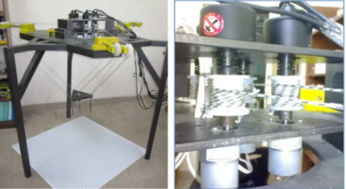
An under-constrained cable robot is designed and man-ufactured in Iran University of Science and Technology (IUST), called ICaSbot, which supports six DOFs in-cluding three translational and three rotational move-ments of the end-eector by the aid of six active cables and six DC motors. A scheme of the mentioned robot can be seen in Figure 5(a) [19]. The experimental tests are conducted on this robot in order to verify the eciency of the proposed controlling strategy of the motors. A hardware setup is designed and man-ufactured, and also a supporting software package is programmed for conducting the required experimental tests and evaluating the required parameters of the motors' equations. The hardware setup is presented in Sections 3. 1, 2 & 3 and the related supporting softwares are presented in Section 3.4.
3.1. Designed hardware setup
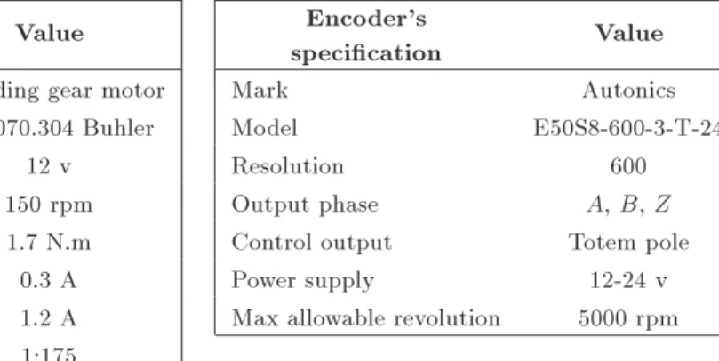
Six motors are selected for the robot whose specica-tions are listed in Table 1. Each motor is connected to an encoder by a 3 cm diameter circular 2shaft which has a high resolution precision of 4600 pulses per rev. The cable which transfers the load weight is passed over a pulley and wrapped around a shaft. As Table 1 shows, this 12 Volt and 17 watt geared motor runs with 150
Figure 5. (Left) The ICaSbot robot. (Right) The assembled system, from top to down: 1- Encoder 2- Shaft 3-Motor.
Table 1. The specications of the selected motor (left) and encoder (right). Motor's
specication Value
Encoder's
specication Value
Mark Retarding gear motor Mark Autonics
Model 1.61.070.304 Buhler Model E50S8-600-3-T-24
Reference voltage 12 v Resolution 600
No load speed 150 rpm Output phase A, B, Z
Stall torque 1.7 N.m Control output Totem pole
No load current 0.3 A Power supply 12-24 v
Stall current 1.2 A Max allowable revolution 5000 rpm Reduction ratio 1:175
Weight 220 g
rpm (in free running condition). Other specications of the motor and encoder are listed in Table 1. Also, six loadcells are employed to evaluate the actual torque of each motor, and improve it in a PD controller of motor current. The assembled system of encoder, shaft and motor is shown in Figure 5.
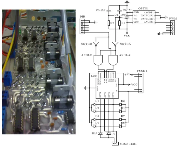
3.2. Printed Circuit Board (PCB) of motor's drivers
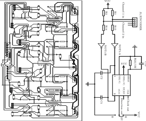
In this test, PWM method is used for regulating the input voltage. In PWM method, the desired pulse width is amplied by a motor driver IC, L298. The PCB converts the command (modulating) signal to a pulse-width modulated output. The lower limit of PWM is 0 V and the upper one is 12 V. Generally, the larger command signal produces the wider pulse. The mentioned PCB and its layout are shown in Figure 6. 3.3. Printed Circuit Board (PCB) of encoders The encoders used in this hardware setup have high resolution precision of 4 600 pulses per rev; two output signals of encoders have a 90 degree phase shift. It is possible to connect the encoders to the data card reader directly without using any intermediate PCB, and estimate the angular velocity and the motion direction, using the phase shift between the two output signals; however, it is preferred here to use a designed intermediate PCB in order to increase the precision and reduce the amount of mathematical calculation.
The designed PCB increases the reading precision from 600 to 2400 pulses per rev, and the output signal received by data cart reader is a square shape signal which varies between 0 and 1 V. The received signals can be read by the aid of a proper software package. The PCB reads rotary encoder's output and its layout are shown in Figure 7. The PCBs, data card reader's ports and the power supply are installed in hardware setup box. A view of the hardware setup box is shown in Figure 8.
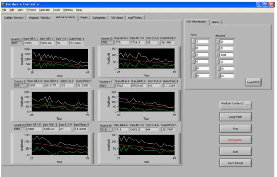
3.4. Software setup
A Graphical User Interface (GUI) software setup which reads the encoders' output signals, using data card reader, is programmed in the LabVIEW environment. A panel of the GUI-software setup is shown in Figure 9. Using this software setup, the user is able to generate the plan of robot's trajectory and run the robot to move within the desired path. It is also possible to run each motor separately with a desired speed by producing its related PWM. The software setup sends the command signal to each motor, and determines the pulse width and voltage level of PWM signal. It also reads the output signals of encoders and calculates the position, orientation, linear velocity and angular velocity of the end-eector. It also plots the motion diagram, position and angular velocity of each motor in a real-time way. In Figure 9, a panel of the software is shown in which the desired and actual positions of six motors are being plotted simultaneously in a real-time way.
4. Experimental tests
4.1. Extracting the equations of the motors In order to extract the equations of the motors, the pro-le of Speed-PWM is rstly obtained for two dierent weights, for both upward and downward motions of the motor. Not only these proles are evaluated for steady state response of the motor (after overcoming the initial inertia and friction of the motor), but also they are obtained for transient state of the motor motion (rst 0.2 seconds when the motor starts its motion from static condition). The reason of this selection is that the controlling step of the motor is 0.2 seconds, and so every 0.2 seconds, a new set-point is considered for the motor. So if the motor is going to start its motion from static condition, it follows the dynamic response of the second proles, while the rst proles are the pattern of the motor behavior during its dynamic rotation period.
Figure 6. Printed Circuit Board (PCB) regulates the motor's angular velocity (left) and its layout (right).
In Figure 10, the prole of the motor is plotted for the rst 0.2 seconds of motion for upward direction while Figure 11 is related to the steady state condition. The horizontal axis is the angular velocity of the motor based on RPM, while the vertical axis is the percentage of PWM. In each gure, two proles are plotted for which the rst is related to the load of 200 gr. and the second is related to the load of 460 gr. Also, the curve which is tted on them can be seen in the proles for which the procedure of their derivation is described in the next section. The proles are shown for the rst two motors, and the rests are not plotted since they are similar. In these gures, y is the required PWM of the motors and x is the motor speed.
The reason of choosing two dierent weights is that two unknown variables will be appeared in the equation of the motors, which should be evaluated using two equations. Finally the reason of conducting the tests for two upward and downward directions is attributed to the fact that the motors have dierent dynamic behavior in upward and downward directions, because of the dierence of breaking force produced by the gearbox as a result of gravity for dierent voltages. The weights 200 gr. and 460 gr. are chosen to perform the interpolation and nding out
the unknown variables of the motor equation, since the maximum and minimum workspace loads of each motor corresponding to the weight of the end-eector are within the mentioned range. The cables of the robot which bear the load are suspended through some drums which are eventually controlled by the aid of motors' rotation. Although the mentioned method is dependent on the workspace of the robot and the resolution of the conducted calibration tests, its advantage is that there is no need to extract the model of the motor, and also it provides a high accurate response of the motor (since both of speed and torque are included) with low processing calculation (since there is no need to solve the dynamics of the motor in a real-tem way), which is suitable for online applications of robot procedure.
So, the torque of the motor can be calculated based on the tension of the cables through the following formula:
= rmg: (13)
In this equation, r is the radius of the drum, m is the mass of the weight and g is the gravitational acceleration. According to the mentioned equation, the torque of the motor is calculated for two loads.
Figure 7. Circuit diagram of the PCB reads rotary encoder's output (left) and its layout (right).
Figure 8. A view of the hardware setup box of the ICaSbot: the PCB reads rotary encoder's output (up) and the PCB regulates the motor's angular velocity (down).
For carrying 200 gr. load, the motor torque is 0:0294 (N.m), and for the 460 gr. load it is 0.0676 (N.m).
For conducting the upward motion test of the motor, the percentage of PWM of the motors is grad-ually increased from zero to 100, up to the threshold of the motor rotation. This value of PWM forms the rst point of the proles. The rest of the points are also provided by recording the angular velocity of the
motor related to each percentage of PWM. Finally, six proles for upward motion and six proles for downward motion of the motors are derived, based on the mentioned procedure. These proles are shown for the rst two motors in Figures 10 and 11, and similar trends exist also for the rest of the motors.
4.2. Curve tting and extracting the nalized equations
Based on the gained proles of previous section, it is obvious that the relation between PWM and motor speed is not perfectly linear. Since the trend is more like a polynomial, a curve of order three is tted on the gained proles. Also, these proles are extracted within our workspace, which is under 50 rpm.
Two dierent weights within the workspace range of the robot are chosen to conduct the tests in order to perform a precise interpolation and evaluate the equations. Also, since the response of the motors for their upward and downward directions is dierent, these tests are repeated for both directions. The following curve is employed to be tted on the PWM-speed proles:
Figure 9. The Graphical User Interface (GUI) software setup programmed in LabVIEW environment.
Figure 10. The extracted proles of the 1st motor related to the loads of 200 and 460 g. conducted in upward direction (left) and downward direction (right) for the rst 0.2 seconds (the transient state).
Figure 11. The extracted proles of the 1st motor related to the loads of 200 and 460 g. conducted in upward direction (left) and downward direction (right) for ultimate velocity condition (the steady state condition).
In this equation, f, e and d are the gains of motor speed in the mentioned polynomial function, and c is a linear function of the applied torque of the motor, which can be stated as:
c = a + b: (15)
Substituting Eq. (15) in Eq. (14) results in Eq. (12). In order to nd out the values of a and b in Eq. (15), two dierent weights are suspended through the motor for both directions, and the weight of 200 gr. is considered as the reference load, since it is the load which is produced by the aid of the weight of the sole end-eector on each cable. Two equations, as below, will be produced:
c1= 0:0294 a + b; (16)
c2= 0:068 a + b: (17)
In these equations, the value of c1is the constant of the
tted curve for the load of 200 gr. for upward motion of the motor, and c2is the same value for the weight of
460 gr. The values of these constants are contrariwise for the downward motion of the motor. So, as it can be seen from the gures, the proles related to the weight of 460 gr. is upper than the one which is extracted for the weight of 200 gr. for upward motion, while this sequence is contrariwise for the downward motion of the motor as it was expected (The speed of downward motion of the motor is obviously faster for the heavier load as a result of a unique PWM and vice versa). Also, the value of a in these equations are the torque of the motors, and it is related to the weight of 200 gr. for the rst equation and 460 gr. for the second one.
Eventually, twelve equations can be extracted for upward and downward motions of the motor during both transient state (rst 0.2 seconds) and steady state
responses of the motor. Twelve equations related to transient state are listed in Table 2, and the ones related to steady state are listed in Table 3.
The relation between torque and speed for a DC motors is roughly linear, and its linear equation can be used for control procedure. Moreover, the relation between speed and current is also linear (Figure 12). However, this relation is not perfectly linear, and considering it a linear function causes some inaccuracy in the tracking procedure. In this paper, we have established the exact prole between torque-speed and PWM by the aid of experimental tests. As can be seen in Figure 13, this relation is not perfectly linear and it can be expressed as a polynomial function of order three. Thus, more accuracy can be provided by the aid of this prole. The reason of this nonlinearity can be justied by using PWM rather than voltage.
4.3. Tuning the PID gains
After evaluating the required PWM of the motors based on the computed torque method and feedback
Figure 12. The speed-torque relation of motor [6]. Table 2. The obtained equations of motors in transient state.
Direction Motor number Obtained equations
Upward
1 PWM = 0:00327 _2+ 0:27908 _ + 108:55 + 8:59
2 PWM = 0:00344 _2+ 0:30371 _ + 108:81 + 8:13
3 PWM = 0:00357 _2+ 0:27498 _ + 113:21 + 8:16
4 PWM = 0:00384 _2+ 0:28683 _ + 101:55 + 8:38
5 PWM = 0:00278 _2+ 0:32256 _ + 111:13 + 8:08
6 PWM = 0:00412 _2+ 0:22306 _ + 125:65 + 7:78
Downward
1 PWM = 0:00313 _2+ 0:23742 _ 49:74 + 9:17
2 PWM = 0:00450 _2+ 0:16908 _ 41:45 + 10:07
3 PWM = 0:00387 _2+ 0:21694 _ 56:99 + 9:8
4 PWM = 0:00439 _2+ 0:23088 _ 47:15 + 9:17
5 PWM = 0:00349 _2+ 0:25659 _ 43:78 + 9:53
Downward
2 PWM = 0:00008 _3 0:00619 _2+ 0:28112 _ 51:81 + 8:34
3 PWM = 0:00006 _3 0:00509 _2+ 0:28136 _ 64:76 + 8:04
4 PWM = 0:00008 _3 0:00582 _2+ 0:30402 _ 83:16 + 8:55
5 PWM = 0:00011 _3 0:00902 _2+ 0:37596 _ 51:81 + 7:66
6 PWM = 0:00006 _3 0:00420 _2+ 0:24346 _ 57 + 7:47
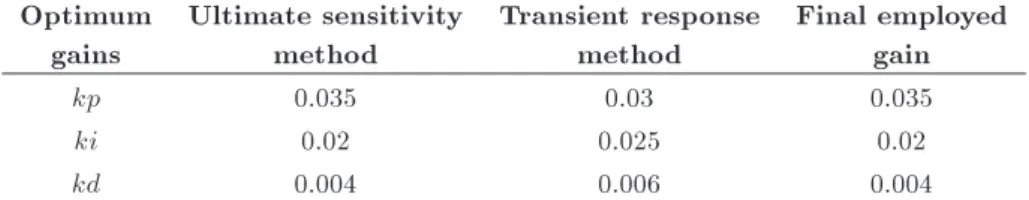
Table 4. Optimum gains obtained using Ziegler-Nichols method. Optimum
gains
Ultimate sensitivity method
Transient response method
Final employed gain
kp 0.035 0.03 0.035
ki 0.02 0.025 0.02
kd 0.004 0.006 0.004
Figure 13. The angular velocity-torque relation of motor for dierent PWM signal.
linearization as the feedforward term of controlling signal, it is required to improve it, using a PID controller. First, the voltage is controlled using motor speed feedback:
PWM =PWMf+ kd(d0 a0) + kp(d a)
+ ki Z
(d a); (18)
where PWMf is the feedforward term of the controlling
signal, which is evaluated by the aid of Eq. (12), d
is the desired angular velocity of the motors com-puted through the inverse kinematics of the robot, a is the actual value of the same term and kp, kd
and ki are the gains of feedback controller of motor speed, which should be properly optimized. There are a lot of approaches for tuning and optimizing the gains of a PID controller [20-22]. Some of them are depended on the dynamic model of the system and some are independent. Ziegler-Nichols, Cohen-Coon and Chien-Hrones-Reswick are of the most famous approaches [20].
In this research, Ziegler-Nichols is used in order to tune the PID gains of the motors. This method is based on two algorithms including transient response method and ultimate sensitivity method. The optimum gains are obtained using both mentioned algorithms in this paper. The results are considerably similar, and they are listed in the Table 4. These values are employed for the installed PID of the robot motors.
In the mentioned controlling strategy for the motor, just the feedback of the motor speed is used to improve the feedforward term of PWM. Since, based on this algorithm, there is no control on the current or torque of the robot's motor, the mentioned controlling loop can be even strengthened using the feedback terms of actual torque of the motor. Since
the desired torque of the motors can be calculated using the inverse dynamics by the aid of Eq. (7) and the actual torque of the motor can be estimated using the employed loadcells in the robot, it is possible to increase the accuracy of the designed controller by using the controlling feedback of the motor torque. Considering the fact that both speed and torque of the motors are included in the feedforward term, by the aid of the mentioned strategy, not only the voltage and speed of the motor can be improved using the feedback of the motor speed (encoders), but also the current and torque of the robot can be modied using the feedback of the motor torque (Loadcell). So, the following formula is used as the nalized required PWM of the motors:
PWM =PWMf+ kd(d0 a0) + kp(d a)
+ ki Z
(d a) + kd2(d0 a0)
+ kp2(d a) + ki2
Z
(d a); (19)
where kd2, kp2 and ki2 are the PID controlling gains related to the torque, and d, a are the desired and
actual torque of the motors, respectively. 5. Results
5.1. Experimental Verication
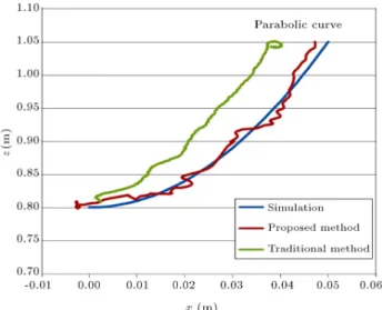
In order to verify the correctness of experimental installation and validate the eciency of the proposed controlling method, the results of experimental test conducted on the ICaSbot, in which the motors are controlled by the aid of the proposed algorithm, is compared with simulation results of MATLAB. A parabolic trajectory with the following equation is chosen for the mentioned comparison:
X = (5=5:69 t) 0:01; Y = 0; Z = ((5=5:69 t)2+ 85) 0:01; 0 t 5:69:
(20) Comparison of experimental tracking with simulation path is plotted in Figure 14. In this prole, the performance of a robot is compared between the traditional approach of motor control (using just the encoder feedback) and the new proposed approach in which the feedforward and feedback terms of the motor torque is also considered. It can be seen that a perfect compatibility can be observed between simulation and experimental results as a result of the designed motor controller. Also, it is obvious that the performance of the proposed method is considerably increased com-pared to the traditional method of controlling a DC motor, and the error is decreased more than 50%.
Figure 14. Tracked parabolic path by the robot (X-Z plan) and its comparison between simulation and experiment with and without torque consideration.
Comparison of angular velocity of the motors between simulation and experimental results are shown in Figure 15 for the six motors. Again, here the proles are compared for two mentioned approaches. Not only an acceptable compatibility can be observed between experiment and simulation, but also it can be con-cluded that the proposed method provides a smoother response of the motor. The reason is contributed to the fact that in traditional approach of controlling the motor, just the feedback of the motors are used which results in more uctuated response of the motor speed, while using the feedforward and also feedback terms of motor torque helps the controller to smooth down these unwanted uctuations.
Since the actual torque of the motors is required in this approach, they should be monitored by the aid of loadcells. Comparison of the tension of the motors between simulation and experimental data is also shown in Figure 16 for the six motors.
Again, a good compatibility can be observed between simulation and experimental results, which shows the eciency of the proposed controller. The little vibrating behavior of the experiment prole around the simulation path can be justied by the motor friction, clearance and also the resolution and accuracy of the encoders. Generally, it can be seen that the deviations of the experimental angular velocity of the motors compared to the desired simulation path, by the aid of the proposed controller and so the integral of the area under the motors speed proles, are roughly equal for simulation and experiment, which provides a similar summation of rotating angle of the motors. Error of the motor speed compared to its desired value, which is extracted through the inverse kinematics, is depicted in Figure 17 for the six motors.
Figure 15. Angular velocities of the six motors for tracking the parabolic path and its comparison between simulation and experiment with and without torque consideration.
Figure 16. Comparison of the experimental torque of the six motors for tracking the parabolic path with simulation.
the motors' speed is less than 0.7 rad/s which is a good record and proves the eciency of the implemented controller. Also again, here the error related to the proposed controlling methodology is decreased consid-erably compared to the traditional control algorithm of DC motor. The oset and vibrations are mostly related to the gearbox clearance, high inertia and friction of
Figure 17. The error of motor speed and position in parabolic path tracking.
the motors and the resolution of the encoders. The order of the errors are increased a little bit at the end of the tracking procedure, which is related to the braking procedure of the motors in the last moments of tracking in experimental tests, which is not modeled in the simulation (according to the equation of the predened trajectory). Moreover, the normal error of the proposed strategy is decreased more than 50% (3 cm error for traditional method versus 1 cm for the proposed method).
6. Conclusion
In this paper, the required PWM of the DC motors of a cable suspended robot was evaluated for online controlling of the end-eector in a predened trajectory in a way that both the desired angular velocity and desired torque of the motor can be provided, and eventually results in an accurate tracking. A novel and accurate method for simultaneous control of speed and torque of the motor is proposed, which is not dependent on the model of the motor. These equations were extracted experimentally as a function between PWM, torque and the speed of the motors, while the data sheet and parameters of the motors were not available. Both the transient and steady state equations were estimated separately for both upward and downward motions of the motor. It was seen that the extracted formulation of the motors have a considerable compati-bility up to 90% with the points of look-up table of the
motor. The advantage of the presented method over look- up table is its higher analyzing speed, its online capability and its independency to motor parameters and datasheet.
This simultaneous control of torque and speed of the motor is provided using inverse dynamics of the robot together with feedback linearization method. The rst loop of PID controls the voltage of the motor and improves its speed, while the second one controls the current of the motor and improves its torque. Thus, not only both the speed and torque of the motor are considered in the feedforward term of motor control, both of them are also improved using PD controller. It was also investigated that using inverse dynamics of the motor, as the feedforward controlling term of the motor results in faster response of the dynamic of the motor, which realizes more accurate tracking for robotic applications. Good compatibility between the tracked trajectory of the end-eector for the simulation and experimental results approved the eciency of the proposed joint space controlling strat-egy of the motors. For all of the comparative proles consisting of the path, motor speed and its related error, the performance of the proposed controlling strategy of a DC motor in a robot is considerably increased (more than 50%), which proves the eciency of the proposed method. Also using the feedback and feedforward terms of the motor torque have decreased the uctuations related to the motor speed, which is highly appreciated. A delay was observed between experimental and simulation proles, which can be referred to as the high inertia and friction of the motors, which are not modeled in the simulation. Also, the vibrating response of the motor speed compared to the smooth simulation results is due to the clearance and exibility of the motor and robot structure which are not modeled in the simulation. It was seen that the integral area under both experimental and simulation proles of the motor speed proles is roughly similar as a result of good compensation of the proposed controller.
References
1. Shaee Alaviche, H. \Desiging and manufacturing of a six cable robot for ponit to point motion in the robot workspace", M.Sc. Thesis, School of Mechanical En-gineering, Iran University of Science and Technology (2009).
2. Imanian Najafabadi, A. \Hardware development of the icasbot in close loop method", M.Sc. Thesis, School of Mechanical Engineering, Iran University of Science and Technology (2010).
3. Rashid, M.H., Power Electronics Handbook, Second Edn., Elsevier/Academic Press (2007).
7. Allaoua, B., Laou, A., Gasbaoui, B. and Abderrah-mani, A. \Neuro-fuzzy DC motor speed control us-ing particle swarm optimization", Leonardo Electronic Journal of Practices and Technologies, ISSN 1583-1078, 15, pp. 1-18 (2009).
8. Namazov, M. \DC motor position control using fuzzy proportional-derivative controllers with dierent de-fuzzication methods", TJFS: Turkish Journal of Fuzzy Systems an Ocial Journal of Turkish Fuzzy Systems Association, 1(1), pp. 36-54 (2010).
9. Koksal, M. and Yenici, F. \Position control of a per-manent magnet DC motor by model reference adaptive control", IEEE International Symposium on Industrial Electronics (2007).
10. Arez, L., Romero, J. and Sira, H. \Algebraic identi-cation and control of an uncertain DC motor using the delta operator approach", 7th International Con-ference on Electrical Engineering, Computing Science and Automatic Control (CCE 2010), Tuxtla Gutierrez, Chiapas, Mexico (2010).
11. Hashemi, Z., Mardaneh, M. and Sha Sadegh, M. \High performance controller for interior permanent magnet synchronous motor drive uusing articial intelligence methods", Scientia Iranica Journal, 19(6), pp. 1788-1793 (2012).
12. Liu, J., Zhang, P. and Wang, F. \Real-time DC servo motor position control by PID controllers using lab-view", International Conference on Intelligent Human-Machine Systems and Cybernetics (2009).
13. Altayef, J. and Qun-xiong, Z. \Real-time DC mo-tor position control by (FPID) controllers and de-sign (FLC) using labview software simulation", IEEE (2010).
14. Yan-hong, D., Shan, W. and Liu Hua, H. \PID controller optimization of mobile robot servo system", IEEE (2011).
15. Reyes-Reyes, J., Astorga-Zaragoza, C-M., Adam-Medina, M. and Guerrero-Ram rez, G-V. \Bounded neuro-control position regulation for a geared DC mo-tor", Journal of Engineering Applications of Articial Intelligence, 23(8) (2010).
pagebreak[3]
16. Alp, A.B. \Cable suspended parallel robots", MSc. Thesis, Mechanical Engineering Department, Univer-sity of Delaware (2001).
opment of ICaSbot a cable suspended robot with 6 DOFs", Arabian Journal for Science and Engineering, DOI: 10.1007/s13369-012-0352-9 (2011).
20. Vukic, Z. and Kuljaca, O., Lectures on PID Con-trollers, University of Zagreb (2002).
21. Kilian, C.T., Modern Control Technology - Compo-nents & Systems, Delmar Thomson Learning (2001). 22. Rezaee, M. and Fathi, G.R. \Obtaining the DC
motor's parameter, exprimentally, and study on the eect of self-induction coecient in the stability of a position control system", 11th Iranian Conference on Manufacturing Engineering (ICME), The University of Tabriz, Iran (2010).
Biographies
Moharam Habibnejad Korayem was born in Tehran, Iran, 1961. He received his BSc (Hon) and MSc degrees in Mechanical Engineering from Amirkabir University of Technology in 1985 and 1987, respec-tively. He obtained his Ph.D degree in Mechanical En-gineering from the University of Wollongong, Australia, in 1994. He is a Professor in Mechanical Engineering at Iran University of Science and Technology. He has been involved in teaching and research activities in the robotics areas at Iran University of Science and Technology for the last 17 years. His research interests include dynamics of elastic mechanical manipulators, trajectory optimization, symbolic modelling, robotic multimedia software, mobile robots, industrial robotics standard, robot vision, soccer robot and the analysis of mechanical manipulator with maximum load carrying capacity. He has published more than 400 papers in international journals and conferences in the robotic area.
Ali Imanian was born in Najafabad, Iran, 1985. He received his BSc degree in Manufacturing from Shahid Rajaee University, Tehran, in 2009 and his MSc degree from Iran University of Science and Technology in 2011 in the eld of mechatronic. He has been involved in teaching and research activities for more than 2 years in the eld of manufacturing, mechatronic and robotic in dierent universities. He has 3 patent records and published 2 papers in international conferences.
Hami Tourajizadeh was born in Tehran, Iran, 1984. He received his BSc degree in Mechanical Engineering from KNT University of Technology in 2006 and his MSc degree from Iran University of Science and Technology in 2008 in the eld of applied mechanical design. He is now a PhD candidate of IUST in the same eld, branch of control and vibration. Five ISI papers, several accepted conferences and two booked inventions are the results of his researches so far. He has been involved in teaching and research activities for more than 2 years in the eld of control and dynamics in dierent universities. His research interests include robotic systems, automotive engineering, control and optimization, parallel manipulators, industrial automa-tion and mechatronic systems.
Saeed Khayatzadeh was born in Mashhad, Iran, 1988. He received his BSc in Mechanical Engineering from Isfahan University of Technology Iran, in 2010. He obtained his MSc degree from Iran University of Science and Technology in 2012 in the eld of biomechanical engineering. He is now a PhD can-didate at the University of Illinois at Chicago, USA in bioengineering, branch of biomechanical engineer-ing. He was ranked top 0.73% in Iran's National Undergraduate Entrance Exam (among more than 332,000 participants) and top 3.3% in Iran's National Graduate Entrance Exam (among more than 13,000 Mechanical Engineers). He was ranked rst among MSc students of the school of mechanical engineering admitted in 2010, and also he was announced one of the honored students among them in the next academic year 2011-2012, again. Excluding this article, his 4 under-review-papers and two presented international conference papers are the results of his researches in robotics. He has been involved in work-group research activity for more than one year in the eld of robotics at robotics lab of IUST. His research interests include mechatronic systems, robotic systems, automotive en-gineering, controlling systems, image processing, vision
control, robotic sensors and real-time signal processing in robotics.
Seyed Mohammad Ebrahim Maddah was born in Kordkuy, Iran, 1987. He received his BSc in Manufacturing Engineering from Tabriz University, Tabriz, Iran, in 2009, and his MSc degree from Iran University of Science and Technology in 2011 in the eld of mechatronic. He is now a Phd candidate at Babol University in Manufacturing Engineering. One accepted conference is the results of his researches. He has been involved in teaching and research activities for one year in dierent universities. His research interests include robotic systems, manufacturing process and automation.
Ali Tajik was born in Tehran, Iran, 1985. He received his BSc degree in Mechanical Engineering from Islamic Azad University, Takestan Branch, in 2008 and his MSc degree in Mechanical Engineering from Islamic Azad University, Science & Research Branch in 2011. He has published more than 2 papers in international journals and conferences about tension mechanism in cable robot and its application. His research interests include robotic systems, parallel manipulators and mechatronic systems, mechanical design, industrial and intelligent robots.
Soleyman Manteghi was born in Damghan, Iran, 1980. He received his BSc degree in Electrical Engi-neering from Malek-e-Ashtar University of Technology in 2003, and his MSc degree in Computer and Mecha-tronics Engineering from Islamic Azad University, Sci-ence & Research Branch in 2013. He has published more than two papers in journals and conferences and one book chapter about control of cable robot and its applications. His research interests include robotic systems, parallel manipulators and mechatronic systems, mechanical design, industrial and intelligent robots.
![Figure 1. Scheme of cable robot [13].](https://thumb-us.123doks.com/thumbv2/123dok_us/8393955.2230193/3.892.462.802.538.1127/figure-scheme-of-cable-robot.webp)
![Figure 2. Scheme of the motor [13].](https://thumb-us.123doks.com/thumbv2/123dok_us/8393955.2230193/4.892.534.757.653.932/figure-scheme-of-the-motor.webp)
![Figure 12. The speed-torque relation of motor [6].](https://thumb-us.123doks.com/thumbv2/123dok_us/8393955.2230193/10.892.487.817.554.780/figure-the-speed-torque-relation-of-motor.webp)