Development and performance of a movable smart
vertical connector in a modular roadway slab
S.B. Park
a, W.S. Kim
a;, Y. Jeong
a, J.J. Song
band S.Y. Lee
b a. Department of Civil Engineering, Chungnam National University, Daejeon, Korea.b. Korea Institute of Construction Technology, Goyang-si, Gyeonggi-do, Korea. Received 22 May 2014; received in revised form 13 April 2015; accepted 2 June 2015
KEYWORDS Modular roadway slab;
Anchor bolt; Finite element analysis; Horizontal displacement; Internal forces.
Abstract.For many years, transportation agencies have been struggling to provide rapid roadway construction and repair work with minimal disruption to trac and maintenance over the service lifetimes. Precast members provide the characteristics of a controlled roadway quality and rapid construction, while the ller between the slabs can be damaged due to the penetration of water and debris. Also, vertical anchor bolts connecting the slabs and crossbeams are associated with unexpected displacement. In this study, a nite element analysis is conducted to develop a modular roadway slab. Two preliminary analysis models are proposed with varying boundary conditions. A combination of various loads was used to determine the appropriate boundary conditions. The model with pinned supports at both ends was selected after comparing the displacements and stresses. Since the model had high horizontal force, due to the boundary conditions pinned at both end of the slab, a new system was developed to reduce the horizontal force by allowing small horizontal displacements at the supports while still fastening vertically. The results of a detailed model analysis show that the displacement allowance with a horizontal ller material should be about 5 mm and the anchor bolts require horizontal shear force of approximately 80 kN.
© 2015 Sharif University of Technology. All rights reserved.
1. Introduction
For many years transportation agencies have been struggling to provide rapid roadway construction and repair work with minimal disruption to trac. They have also pursued satisfactory roadway systems which require minimal maintenance over their service life-times. One possible solution to fulll this concept of ideal maintenance is the use of precast members which can provide high-quality and rapid construction [1]. However, using precast members can also damage the ller used between slabs due to the penetration of water and debris. Also, anchor bolts are associated with unexpected displacement if the force acting on
*. Corresponding author. Tel.: +82 42 821 6584; E-mail address: [email protected] (W.S. Kim)
the anchor bolts is relatively large. Thus, a detailed analysis model was developed to identify the required capacity of a vertical connector that can resist high levels of horizontal shear force and allow thermal movement, despite the presence of water and debris. Although there are relevant studies [2,3] and pilot construction projects in Europe and North America [4-8], Asian countries have not yet started to develop conceptual modular roadway systems. The purpose of this study is to develop a roadway joint system as part of the research into Sustainable-Perpetual-Modular (SPM) roadway systems.
The establishment of appropriate roadway bound-ary conditions to accommodate less displacement and internal force is another goal of the present study. Generally, a modular roadway system is composed of a precast roadway slab, crossbeams, and supporting
study was conducted by computer simulations, using ANSYS [10], to establish the internal forces and dis-placements of these types of slab under various loads. First, the proper boundary conditions were selected in a preliminary analysis with two models. Then, a combination of various loads was used to select the appropriate boundary conditions. Based on the results, a detailed model is developed.
2. Preliminary analysis 2.1. Simplied model
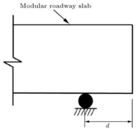
For the preliminary analysis, two dierent boundary conditions were simulated to determine the appropriate vertical connector boundary conditions for a modular slab. Also, support osets (d) were considered for use with actual support conditions, as presented in Figure 2. The support osets were spaced at distances of 0.0 to 0.3 m away from the slab end, after which, the displacements at the top and bottom ends of the roadway slab were investigated under dead, live, and temperature loads. Based on the two boundary conditions and support oset variations, horizontal and vertical displacements and reaction forces were investigated.
2.1.1. Case 1
For Case 1, the proposed boundary conditions are presented in Figure 3. The modular slab has two roller supports at both ends, while a hinge support is located in the middle of the slab. The boundary condition was
Figure 2. Denitions of parameters.
Figure 4. Boundary conditions of Case 2.
proposed to allow minimal thermal movement of the slab.
2.1.2. Case 2
For Case 2, the proposed boundary conditions are presented in Figure 4. The boundary conditions for Case 2 are hinge supports at both ends and in the middle of the slab. The hinge support restricts all displacements except longitudinal bending rotations. Thus, the roadway slab is stable against horizontal and vertical displacements. However, the internal force acting on the ends of the slab is expected to be larger than that of Case 1.
2.2. Loads and material properties
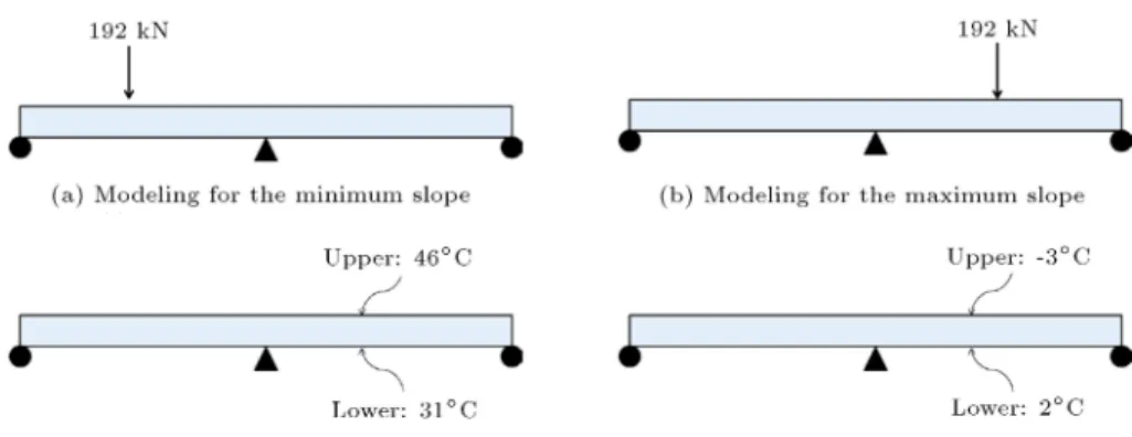
Dead loads, live loads and temperature loads were considered in the analysis. The live loads of KL-510 [11] were based on an inuence line analysis to determine truck locations that produce maximum displacements and internal forces. For the temperature load, both a uniform temperature and a temperature gradient were considered, based on actual roadway temperature measurements by KRPSDG [12]. The truck live load (KL-510) location was categorized into two cases: (1) with a convex shape, and (2) with a concave shape of the right-side span of the slab to obtain the maximum displacement at the slab end. Similarly, the temper-ature loads also considered a convex shape (upper: 46.5C, lower: 29C) and a concave shape (upper:
3C, lower: 2C). Figure 5 shows the application of
live load and temperature load in the numerical model. Table 1 shows the material properties of the modular slab considered in this study.
Table 1. Material properties. Modulus of elasticity
(GPa)
Poisson's ratio
Unit mass (kg/m3)
Figure 5. Live load and temperature load modeling. Table 2. Displacements results.
d (m) Displacements (mm) Concave Convex
Case 1
0.0 0.69 0.93
0.1 0.69 0.94
0.2 0.70 0.96
0.3 0.71 1.03
Case 2
0.0 0.63 0.83
0.1 0.66 0.89
0.2 0.74 1.02
0.3 0.85 1.18
2.3. Analysis results 2.3.1. Displacements
Table 2 shows the displacement corresponding to the slab deection shape of each case. The right-side spans of the slab, depending on the load combinations, were investigated with convex and concave shapes. Both the convex and concave shape analysis results demonstrated that both the horizontal and the vertical displacements increased with an increase in the support oset (d) from the tip of the slab end. Also, the con-vex shape had greater displacement than the concave shape.
2.3.2. Horizontal forces
Table 3 shows the horizontal force of Case 2 under each load. Reaction forces due to self-weight were neglected because the supports of the end tip are xed after the slab is placed at the construction site and deection
Table 3. Horizontal forces of Case 2. d
(m)
Temperature load (kN)
Live load (kN)
Sum (kN)
0.0 -4252 -376 -4628
0.1 -4330 -372 -4702
0.2 -4342 -365 -4707
0.3 -4353 -357 -4710
occurs due to self-weight. Signicant horizontal forces were observed due to the restraint boundary conditions at both ends of the slab. However, those forces may be reduced if the slab can allow a small amount of displacement. Horizontal forces did not occur due to the roller supports in Case 1.
2.3.3. Preliminary analysis results
The analysis results for Case 1 and Case 2 show the smallest displacements with a support oset condition of d = 0:0 m. Although the minimum displacement occurred in Case 1 when d = 0:0 m, Case 2 was considered to be a more stable conguration for actual modular roadway slabs. Also, Case 2 produced high horizontal forces. Therefore, detailed models of the proposed vertical connector that allowed horizontal displacement at the slab ends were investigated. 3. Detailed analysis
3.1. Detailed model
Section 2 of this study is to determine the boundary conditions and optimal parameter `d'. Based on the results, an analysis was conducted to develop a detailed model. The analysis results for both Case 1 and Case 2 show the smallest displacements when the support oset condition had d equal to 0.0 m, as noted above. Although minimum displacement occurred in Case 1, Case 2 was considered to be a more stable conguration for actual modular roadway slabs. However, Case 2 produced high horizontal forces. Therefore, detailed models for the proposed vertical connector that allowed horizontal displacement at the slab ends were investi-gated. The detailed model is a two-span continuous beam and is reinforced with cross beams under the slab. Between the slab and cross beam, a steel anchor is proposed, as shown in Figure 6, with a debonding treatment around the anchor in the slab.
3.2. Loads and material properties
The same loads and material properties were used in the preliminary model. In addition, the long-term behavior of the concrete creep and shrinkage
Table 4. Material properties. Modulus of
elasticity (GPa)
Poisson's ratio
Unit mass (kg/m3)
Anchor bolt 200 0.3 7850
Slab 36.6 0.18 2500
Mortar 18.5 0.18 2150
Cross beam 36.6 0.18 2500
were considered. The preliminary analysis models showed that the temperature loads induced the greatest displacements and horizontal forces compared to the other loads. Thus, only the temperature loads were considered in the parametric study. Table 4 shows the material properties of the components of the detailed models assessed in this study.
3.3. Parameters
In detailed model, (i) the distance to the anchor bolts in the slab (a), (ii) the distance to the anchor bolts in the cross beam (b), and (iii) the height of the mortar (h) were considered as parameters. Table 5 shows the possible ranges.
Also, in the parametric study, the displacements of the slab and the internal forces of the anchor bolts were analyzed. Figure 7 shows the denitions of the parameters. Here, A denotes the upper slab, B is the lower slab, C is the upper anchor bolt, and D denotes the middle anchor bolt.
Table 5. Case ID and name for a parametric study. Case ID Case name
1 a150b100h30 2 a150b100h50 3 a150b200h30 4 a150b200h50 5 a200b100h30 6 a200b100h50 7 a200b200h30 8 a200b200h50
Figure 7. Cross-section of the model.
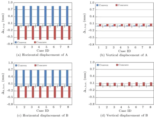
3.4. Parametric study results 3.4.1. Slab displacements
Figure 8 shows that the horizontal displacements of the convex shape are greater than the vertical displace-ments of the concave shape. Moreover, the resulting values are constant in accordance with the parameters. 3.4.2. Anchor bolts displacements
Figure 9 shows the displacements of C and D. The horizontal displacement of C is greater than the other displacements at C. Also, the gure shows that the displacements of C are greater than the displacements of D.
3.4.3. Anchor bolts internal forces
Figure 10 show that the tensile forces were greater than the shear forces. Similarly, the resulting values are constant, in accordance with the parameters.
3.5. Comparison with Case 2 and detailed model
The internal forces of case 2 showed that restrained and large horizontal reaction forces were induced. For the detailed model, the internal force is signicantly reduced, due to the displacement, to allow for the anchor bolts. Table 6 shows the internal forces of both Case 2 and the detailed model.
Table 6. Internal force comparison. Fx (kN) Fy (kN) Fz (kN)
Case 2 275 3872 0
Figure 8. Slab displacement results.
Figure 9. Anchor bolt displacements.
3.6. Additional parametric study
In the parametric study results, the displacements values were found to be constant in accordance with the parameters. However, the internal force of the anchor bolts aects the parameter `a'. As a result, a150b100h30 was deemed suitable in terms of economic eciency, constructability, and usability. Additionally, a parametric study was conducted to assess only parameter `a'. Parameters `b' and `h' were xed and
parameter `a' was changed from 100 to 300. Figure 11 shows the internal force results. Shearing forces (longi-tudinal and transverse) show no response. In contrast, the axial force showed a response.
3.7. Load combination results
The case with the parameter a150b100h30 showed the smallest displacements and internal forces. Thus, this case was selected to represent the appropriate
parame-Figure 11. Internal forces with respect to a.
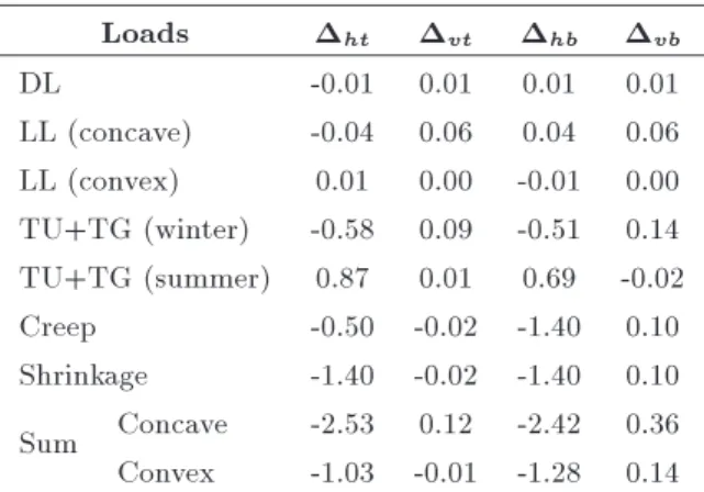
ters. The combination of the load when the span on the right side of the slab has a convex shape is as follows: Dead load + Live load (convex) + Temperature load (summer) + Creep and shrinkage. On the other hand, the combination of the load when the span of the right side of slab has a concave shape is as follows: Dead load + live load (concave) + Temperature load (winter) + creep and shrinkage. Table 7 shows the displacement results of the slab. Tables 8 and 9 show the anchor bolt displacement at the top and midpoint, respectively, and Table 10 shows the internal forces of the anchor bolt. 4. Conclusion
A preliminary analysis based on two boundary condi-tions investigated the inuence of boundary condicondi-tions
Table 7. Slab displacements.
Loads ht vt hb vb
DL -0.01 0.01 0.01 0.01
LL (concave) -0.04 0.06 0.04 0.06 LL (convex) 0.01 0.00 -0.01 0.00 TU+TG (winter) -0.58 0.09 -0.51 0.14 TU+TG (summer) 0.87 0.01 0.69 -0.02 Creep -0.50 -0.02 -1.40 0.10 Shrinkage -1.40 -0.02 -1.40 0.10 Sum Concave -2.53 0.12 -2.42 0.36 Convex -1.03 -0.01 -1.28 0.14
Table 8. Displacements of the anchor bolt at the top.
Loads x y z
DL 0.00 0.00 0.00
LL (concave) 0.02 0.01 0.00 LL (convex) 0.01 -0.01 0.00 TU+TG (winter) 0.02 -0.51 -0.22 TU+TG (summer) 0.15 0.73 0.33
Creep 0.08 -0.52 0.17
Shrinkage 0.04 -1.40 -0.59 Sum Concave 0.16 -2.42 -0.64 Convex 0.29 -1.19 -0.09 Table 9. Displacements of the anchor bolt at the midpoint.
Loads x y z
DL 0.00 0.00 0.00
LL (concave) 0.01 0.00 0.00 LL (convex) 0.01 0.00 0.00 TU+TG (winter) -0.01 0.03 -0.18 TU+TG (summer) 0.08 0.06 0.23
Creep 0.06 0.08 -0.23
Shrinkage 0.04 -0.16 0.13 Sum Concave 0.19 -0.02 0.13 Convex 0.10 -0.05 -0.28
LL (concave) 0.01 0.00 0.00
LL (convex) 0.01 0.00 0.00
TU+TG (summer) 0.08 0.06 0.23 TU+TG (winter) -0.01 0.03 -0.18
Creep 0.06 0.08 -0.23
Shrinkage 0.04 -0.16 0.13
Sum Concave 0.19 -0.02 0.13 Convex 0.10 -0.05 -0.28
on slab and anchor bolt responses. Detailed analytical models were then developed, leading to the following conclusions.
1. For a convex shape, a horizontal ller material set between two slabs needs to allow a distance of at least 2 mm. Similarly, for a concave shape, the horizontal ller between the two slabs needs to allow at least 5 mm;
2. Anchor bolts can be subjected to a maximum of 80 kN horizontal shear force;
3. The vertical displacement is 0.12 mm. This was not considered large enough to cause any rideability problems.
Acknowledgment
This study was supported by the Basic Science Research Program through the National Research Foundation of Korea (NRF), funded by the Min-istry of Education, Science and Technology (NRF-2012R1A1A044378) and by the Korea Institute of Construction Technology through the research project \Sustainable-Perpetual-Modular (SPM) Road System Development."
References
1. Lane, B. and Kazmierowski, T. \Precast concrete slab repair method", Concrete International, 28(11), pp. 29-35 (2006).
2. Houben, L.J.M., Huurman, M., van der Kooij, J. and Poot, S. \APT testing and 3D nite element analysis of `modieslab' modular pavement structures", 2nd Interna-tional Conference on Accelerated Pavement Testing, Minneapolis, MN, USA (2004).
3. Chang, L.M., Chen, Y.-T. and Lee, S. \Using precast concrete panels for pavement construction in Indiana", Report No. FHWA/IN/JTRP-2003/26, Joint
Trans-Transportation Research, The University of Texas at Austin (2000).
5. David, K.M., McCullough, B.F. and Burns, N.H. \Construction and preliminary monitoring of the Georgetown", Texas Precast Prestressed Concrete Pavement. Report No. 1517-01-IMP, Center for Trans-portation Research, The University of Texas at Austin (2002).
6. David, K.M., McCullough, B.F. and Burns, N.H. \Construction of the California precast concrete pave-ment demonstration project", Report No. FHWA-IF-06-010, The Transtec Group Inc. (2004).
7. Drago, J. \Innovation fast-setting concrete", Caltrans Journal, 2(4), pp. 46-49 (2002).
8. Kohler, E., du Plessis, L., Smith, P.J. and Pyle, T. \Precast concrete pavements and results of acceler-ated trac load test", International Conference on Optimizing Paving Concrete Mixtures and Accelerated Concrete Pavement Construction and Rehabilitation, Atlanta, GA, USA, pp. 263-282 (2007).
9. Whiteoak, C.D. \Analytical pavement design using programs for personal computers", Highways and Transportation, 37(8), pp. 31-35 (1990).
10. ANSYS Inc. ANSYS APDL Theory Guide, Release 14.5, ANSYS Inc. (2010).
11. Korea Road and Transportation Association \Korean Bridge Design Code (KBDC) (Limit State-based De-sign)", Ministry of land, Transport and Maritime Aairs, Seoul, Republic of Korea (2012) (in Korean).
12. Korea Road and Transportation Association, Ko-rean Roadway Pavement Structural Design Guidelines (KRPSDG), Ministry of land, Transport and Maritime Aairs, Seoul, Republic of Korea (2011) (in Korean).
Biographies
Soobong Park obtained his MS degree in Civil Engi-neering from Chungnam National University, Daejeon, Republic of Korea, in 2015. His research interests include nite element modeling and analysis, and emergency repair of highway bridges.
WooSeok Kim received a PhD degree in Civil Engi-neering from Pennsylvania State University, University Park, PA, USA, in 2008, and currently works in the Civil Engineering Department of Chungnam National University, Daejeon, Republic of Korea. His research interests include bridge engineering and maintenance of infrastructures.