Freescale USB Device Stack
Users Guide
Document Number:USBUG Rev. 12 05/2012
Home Page: www.freescale.com E-mail:
USA/Europe or Locations Not Listed: Freescale Semiconductor
Technical Information Center, CH370 1300 N. Alma School Road
Chandler, Arizona 85224
+1-800-521-6274 or +1-480-768-2130 [email protected]
Europe, Middle East, and Africa: Freescale Halbleiter Deutschland GmbH Technical Information Center
Schatzbogen 7 81829 Muenchen, Germany +44 1296 380 456 (English) +46 8 52200080 (English) +49 89 92103 559 (German) +33 1 69 35 48 48 (French) [email protected] Japan:
Freescale Semiconductor Japan Ltd. Headquarters ARCO Tower 15F 1-8-1, Shimo-Meguro, Meguro-ku, Tokyo 153-0064, Japan 0120 191014 or +81 3 5437 9125 [email protected] Asia/Pacific:
Freescale Semiconductor China Ltd. Exchange Building 23F
No. 118 Jianguo Road Chaoyang District Beijing 100022 China
+86 10 5879 8000
[email protected] For Literature Requests Only:
Freescale Semiconductor Literature Distribution Center 1-800-441-2447 or 303-675-2140
Fax: 303-675-2150
Information in this document is provided solely to enable system and software implementers to use Freescale Semiconductor products. There are no express or implied copyright licenses granted hereunder to design or fabricate any integrated circuits or integrated circuits based on the information in this document.
Freescale Semiconductor reserves the right to make changes without further notice to any products herein. Freescale Semiconductor makes no warranty, representation or guarantee regarding the suitability of its products for any particular purpose, nor does Freescale Semiconductor assume any liability arising out of the application or use of any product or circuit, and specifically disclaims any and all liability, including without limitation consequential or incidental damages. “Typical” parameters that may be provided in Freescale Semiconductor data sheets and/or specifications can and do vary in different applications and actual performance may vary over time. All operating parameters, including “Typicals”, must be validated for each customer application by customer’s technical experts. Freescale Semiconductor does not convey any license under its patent rights nor the rights of others. Freescale Semiconductor products are not designed, intended, or authorized for use as components in systems intended for surgical implant into the body, or other applications intended to support or sustain life, or for any other application in which the failure of the Freescale Semiconductor product could create a situation where personal injury or death may occur. Should Buyer purchase or use Freescale Semiconductor products for any such unintended or unauthorized application, Buyer shall indemnify and hold Freescale Semiconductor and its officers, employees, subsidiaries, affiliates, and distributors harmless against all claims, costs, damages, and expenses, and reasonable attorney fees arising out of, directly or indirectly, any claim of personal injury or death associated with such unintended or unauthorized use, even if such claim alleges that Freescale Semiconductor was negligent regarding the design or manufacture of the part.
Freescale™ and the Freescale logo are trademarks of Freescale Semiconductor, Inc. All other product or service names are the property of their respective owners.
© 1994-2008 ARC™ International. All rights reserved. © Freescale Semiconductor, Inc. 2010–2012. All rights reserved.
Document Number: USBUG Rev. 12
To provide the most up-to-date information, the revision of our documents on the World Wide Web will be the most current. Your printed copy may be an earlier revision. To verify you have the latest information available, refer to:
http://www.freescale.com
The following revision history table summarizes changes contained in this document.
Revision Number
Revision
Date Description of Changes
Rev. 1 05/2009 Alpha Customer Release. Rev. 2 05/2009 Added CDC feature description.
Rev. 3 06/2009
• Added ColdFire V1 support and PHDC Multi-Specialization Device Demo application.
• Changed USB to Serial Demo name to Virtual Communication (COM) Demo.
Rev. 4 09/2009 Launch release. Customized for Medical Applications. Rev. 5 10/2009 Added SD Card demo application.
Rev. 6 04/2010
Updated USB Stack installation and uninstallation and Medical Applications USB Stack directory structure diagram to add support for S08MM128, S08JE128, MCF51MM256, and MCF51JE256 devices.
Rev. 7 06/2010
• Added support for CFV2 devices.
• Rebranded Medical Applications USB Stack to Freescale USB Stack with PHDC.
Rev. 8 09/2010
• Added support for CodeWarrior 10 • Added USB audio demo application
• Fig 2-1:Freescale USB stack with PHDC Directory Structure updated
Rev. 9 01/2011
• Added USB DFU demo application
• Update images in various demo application • Minor editorial changes
Rev. 10 07/2011 • Added battery charging demo application
• USB FATFS User Guide incorporated in the USB User Guide
Rev. 11 03/2012
• Deleted chapters “FAT File System” and “AppendixJ_FATFS_Demo_Test” • Replaced the term "Freescale USB Stack with PHDC" with "Freescale USB
Stack"
• Updated Installer screenshots • Editorial Changes
Freescale™ and the Freescale logo are trademarks of Freescale Semiconductor, Inc. © Freescale Semiconductor, Inc., 2010–2012. All rights reserved.
Rev. 12 05/2012
Added
• Appendix J: Video Device Class Demo Applications • Appendix K: MSD and CDC Composite Demo • Appendix L: HID Audio Video Composite Demo
Before You Begin
1.1 About Freescale USB Stack . . . 1
1.2 About this book . . . 1
1.3 Reference material . . . 3
1.4 Acronyms and abbreviations . . . 3
1.5 Important terms . . . .4
Chapter 2
Getting Familiar
2.1 Introduction . . . .7 2.2 Software suite . . . 7 2.3 Directory structure . . . 7Chapter 3
Freescale USB Stack Architecture
3.1 Architecture overview . . . . 9 3.2 Software flows . . . 10 3.2.1 Initialization flow . . . 10 3.2.2 De-initialization flow . . . 12 3.2.3 Transmission flow . . . 12 3.2.4 Reception flow . . . 14Chapter 4
Developing New Class Drivers
4.1 Introduction . . . 174.2 Steps for developing new class drivers . . . 18
4.2.1 Directory structure . . . 18
4.2.2 Class initialization . . . 18
4.2.3 Class callback routine . . . 20
4.2.4 Class request routine . . . 22
4.2.4.1 Endpoint service routine . . . 23
Chapter 5
Developing Applications
5.1 Introduction . . . 25 5.2 Application interfaces . . . . 25 5.3 Developing an Application . . . 25 5.4 Application design . . . . 385.4.1 Main Application Function . . . 39
Working with the Software
A.1 Introduction . . . 41
A.1.1 Preparing the setup . . . 41
A.1.1.1Software setup . . . 41
A.1.1.2Hardware setup . . . 45
A.1.2 Building the Application with CodeWarrior 6 and CodeWarrior 7 . . . 46
A.1.3 Running the Application with CodeWarrior 6 and CodeWarrior 7 . . . 47
A.1.4 Building and Running the Application with CodeWarrior 10 . . . 50
A.2 Uninstall Freescale USB Stack Software . . . 56
A.3 Important files . . . 58
Appendix B
Human Interface Device (HID) Demo
B.1 Setting up the demo . . . 59B.2 Running the demo . . . 59
Appendix C
Personal Healthcare — Multi-Specialization Device Demo
C.1 Setting up the demo . . . 61C.2 Running the demo . . . 61
Appendix D
Human Interface Device (HID) Demo
D.1 Setting up the demo . . . 71D.2 Running the demo . . . 71
Appendix E
Personal Healthcare – Weigh Scale Device Demo
E.1 Setting up the demo . . . 73E.2 Running the demo . . . 73
Appendix F
SD Card Demo
F.1 Setting up the demo . . . 79F.2 Running the demo . . . 79
Appendix G
USB Audio Demo
G.1 Audio speaker demo . . . 81G.1.1 Setting up the demo . . . 81
G.1.2 Running the demo . . . 82
G.2.2 Running the demo . . . 91
Appendix H
DFU Class Demo
H.1 Setting up the demo . . . 93H.2 Running the demo . . . 94
H.2.1 Driver installation . . . 94
H.2.2 Downloading firmware . . . 101
H.2.3 Upload firmware . . . 107
Appendix I
Battery Charging Device Demo Application
I.1 Setting up the demo . . . 109I.2 Running the demo . . . 110
Appendix J
Video Device Class Demo Applications
J.1 Introduction . . . 113J.1.1 About Video Class demo . . . 113
J.2 USB Video Demo – Internal Flash . . . 113
J.2.1 Overview . . . 113
J.2.2 Setting up the demo . . . 113
J.2.3 Running the demo . . . 114
J.2.3.1Preparing . . . 114
J.3 USB Video Demo — SD card . . . 116
J.3.1 Overview . . . 116
J.3.2 Setting up the demo . . . 116
J.3.3 Running the demo . . . 117
J.3.4 Preparing video data . . . 117
J.3.4.1Running video demo application . . . 121
Appendix K
MSD and CDC Composite Demo
K.1 Introduction . . . 123K.1.1 About MSD and CDC demo . . . 123
K.1.2 Reference material . . . 123
K.1.3 Acronyms and Abbreviations . . . 123
K.2 Setting up the demo . . . 124
K.3 . . . Running the demo 125
Appendix L
HID Audio Video Composite Demo
L.1 Introduction . . . 143L.1.2 Reference material . . . 143
L.1.3 Acronyms and Abbreviations . . . 143
L.2 Setting up the demo . . . 144
L.3 Running the demo . . . 145
L.4 Video virtual camera feature demo . . . 147
L.5 Audio speaker feature demo . . . 149
Chapter 1 Before You Begin
1.1
About Freescale USB Stack
Universal Serial Bus commonly known as USB is a serial bus protocol that can be used to connect external devices to the host computer. In today's world, it is one of the most popular interfaces connecting devices such as microphone, keyboards, storage devices, cameras, printers, and many more. USB interconnects are also getting more and more popular in the medical segments. The Freescale USB Stack enables you to use Freescale 8-bit, 16-bit, and 32-bit MCUs (for example: Kinetis k40, S08, CFV1, and so on) silicon to make the devices listed above.
It abstracts the details of Kinetis k40, S08, CFV1, and CFV2 devices, and the USB IP used. It provides a higher level interface to the application. The application developers only need to concentrate on the application in hand without worrying about the USB details.
1.2
About this book
This book describes the Freescale USB Stack architecture. Table 1-1 shows the summary of chapters included in this book.
Table 1-1. USBUG summary
Chapter Title Description
Before you begin This chapter provides the prerequisites of reading this book.
Getting Familiar This chapter provides the information about the Freescale USB Stack software suite. USB Stack Architecture This chapter discusses the architecture design of the Freescale USB suite.
Working with the Software This chapter provides information on how to build, run, and debug drivers and applications.
Developing Class Drivers This chapter discusses the steps a developer must take to develop applications on top of the pre developed classes.
Human Interface Device (HID) Demo
This chapter provides the setup and running HID demo using USB stack – Kinetis k40, S08, CFV1, and CFV2 devices are used as examples.
Personal Healthcare – Weigh Scale Device Demo
This chapter provides the setup and running Personal Healthcare – Weigh Scale device demo using USB stack – Kinetis k40, S08, CFV1, and CFV2 devices are used as examples.
Virtual Communication (COM) Demo
This chapter provides the setup and running Communication Device Class (CDC) demo using USB stack – Kinetis k40, S08, CFV1, and CFV2 devices are used as examples. Personal Healthcare –
Multi-Specialization Device Demo
This chapter provides the setup and running Personal Healthcare – Multi-Specialization device demo using USB stack – Kinetis k40, S08, CFV1, and CFV2 devices are used as examples.
SD Card Demo This chapter provides the setup and running Mass Storage Class (MSC) demo using USB stack – Kinetis k40, S08, CFV1, and CFV2 devices are used as examples.
USB Audio Demo This chapter provides information about Audio Demos – how to run Audio Speaker Demo and Audio Generator Demo.
DFU Class Demo This chapter provides information about DFU Class Demo – how to setup the DFU Class Demo and how to run the DFU Class Demo.
Battery Charging Demo Application
This chapter provides the setup and running the Battery Charging Demo Application using USB stack – Kinetis K40, K53 and K60, CF+
FATFS Demo and Test application
This chapter provides the setup and running USB FATFS demo example and USB FATFS test example for CFV1 processors.
1.3
Reference material
Use this book in conjunction with:
• Freescale USB Stack Device API Reference Manual (document USBAPIRM) • Freescale USB Stack Host Users Guide (document USBHOSTUG)
• S08 USB Device Source Code
• ColdFire V1 USB Device Source Code • ColdFire V2 USB Device Source Code • USB Audio Class API Reference Manual • USB Video Class API Reference Manual • USB MCD Class API Reference Manual • USB CDC Class API Reference Manual • USB BM device stack source
• Application Note: Audio Reproduction on HCS12 Microcontrollers (AN2250), Rev. 0, 2002 • File Allocation Table information at http://en.wikipedia.org/wiki/File_Allocation_Table
• FATFS Module Application Note at http://elm-chan.org/fsw/ff/en/appnote.html
• USB Host source code. • USB FATFS source code
• USB HID Class API Reference Manual • USB BM device stack source code
For better understanding, refer to the following documents: • USB Specification Revision 1.1
• USB Specification Revision 2.0
• USB Device Class Definition for Audio Devices Revision 1.1 • USB Device Class Definition for Video Devices Revision 1.0a • S08 Core Reference
• ColdFire V2 Core Reference • ColdFire V1 Core Reference • CodeWarrior Help
• MCF51JM128 Reference Manual
• USB Device Class Definition for DFU Devices Revision 1.1 (also called DFU class specificatio). • MCF52259 Reference Manual
• Battery Charging Specification Rev 1.1 • K60 Sub-Family Reference Manual
1.4
Acronyms and abbreviations
API Application programming Interface CDC Communication Device Class CDP Charging Downstream Port
CFV1 ColdFire V1 (MCF51JM128 CFV1 device is used in this document) CFV2 ColdFire V2 (MCF52221, MCF52259, and MCF52277 CFV2 device is
used in this document) COM Communication
DBCS Double-Byte Character Set DCP Dedicated Charging Port EVB Evaluation
DFU Device Firmware Upgrade FAT File Allocation Table
FATFS File Allocation Table file system HCI Host Controller Interface HID Human Interface Device
IDE Integrated Development Environment JM60 MC9S08JM60 Device
JM16 MC9S08JM16 Device JM128 MCFJM128 Device
JS16 MC9S08JS16 Device K60 MK60N512VMD Device MBR Master Boot Record MSD Mass Storage Device MSC Mass Storage Class M52259 MCF52259 Device
OEM Original Equipment Manufacturer PC Personal Computer
PD Portable Device
PHD Personal Healthcare Device PHDC Personal Healthcare Device Class
SCSI Small Computer System Interface SDP Standard Downstream Port USB Universal Serial Bus
1.5
Important terms
Table 1-2 shows the terms used throughout the book.
Table 1-2. Important terms
Term Description
Class Driver These are the high level function specific drivers that can control large number of different devices of a similar type.
Code Page Code page is another name for character encoding. It consists of a table of values that describes the character set for a particular language.
Cluster To reduce the overheadof managing on-disk data structures, the file system does not allocate individual sectors, but contiguous groups of sectors, called clusters.
Continua Alliance This is a consortium of companies to establish standards for the medical segment devices.
Expansion Card This is the card where the silicon is embedded and can be loaded on to the hardware board.
DemoJM This is the physical hardware where the expansion card with the silicon is mounted.
Enumeration It is a process in the USB protocol by which the host identifies the devices connected to it.
FAT12 A type of FAT file system that uses 12 bits value to address clusters.
FAT16 A type of FAT file system that uses 16 bits value to address clusters.
FAT32 A type of FAT file system that uses 32 bits value (in which 4 bits are reserved) to address clusters.
Kinetis k40, S08, CFV1, and CFV2 Processors
These are low-end family of processors provided by the Freescale.
Long File Name In a file system that supports long file names, a file or directory name can be as long as 255 characters including one or more dots and extensions. A complete path of the file has a maximum of 260 characters, so volumes with many levels of directories must use shorter names.
USB Low Level Drivers USB low level drivers are the driver software layers that interface the hardware and abstracts them for the class drivers.
USB Chapter 9 Requests
These are the framework requests made by the host to the device that the device must respond to. These are defined in Chapter 9 of the USB specification document.
Attach versus Connect A downstream device is considered to be attached to an upstream port when there is a physical USB cable between them.
A downstream device is considered to be connected to an upstream port when there is attached to the upstream port and when the downstream device has pulled either the D+ or D- data line high through a 1.5 K resistor in oeder to operate either as a low or full speed device.
Downstream Port A Downstream Port refers to either a Standard Downstream Port (SDP) or a Charging Downstream Port (CDP).
USB Charger A USB Charger is a device with Dedicated Charging Port, such as a wall adapter or car power adapter.
Portable Device A Portable Device is considered to be any USB or OTG device that is capable of operating from its own battery and it also capable of drawing current from the USB port for its purposes of operating and/or charging its battery.
Weak Battery Threshold
Minimum voltage charge level of a battery such that above this threshold the device is considered to function normally. Dead Battery
Threshold
Maximum charge level of a battery such that below this threshold the device is assumed to not been able to function anymore. Sector Sector is the smallest storage unit in a mass storage medium.
Typically, a sector holds 512 bytes of information. However, some medium can have sector size more than 512 bytes.
Partition A partition is a logical division on mass storage device. The term is also known as Volume or Logical Disk.
Table 1-2. Important terms (continued)
Chapter 2 Getting Familiar
2.1
Introduction
The Freescale USB Stack device contains the low level driver code, commonly used class drivers, and some basic applications. This document intends to help you develop an understanding of the stack and to assist you in developing more classes and applications. The document is targeted for firmware application developers who would like to develop the applications using USB as the transport.
2.2
Software suite
The software suite comprises of the USB low level drivers for the Kinetis k40, S08, CFV1, and CFV2 families, generic class drivers, and applications. The class drivers are programmed with generic code, so they can be used with other processors like CFV1 and CFV2 without a line of code change if the low level drivers comply with the driver interface.
2.3
Directory structure
The software suite has a standard directory structure. You can extend it easily to accommodate more applications, classes, and low level drivers for different processor families.
Chapter 3 Freescale USB Stack Architecture
3.1
Architecture overview
Figure 3-1 shows the Freescale USB Stack architecture.
Figure 3-1. Freescale USB Stack Architecture
The USB stack is mainly divided into three layers with the applications being developed on top of them. The layered architecture helps the application developers concentrate on developing the application without being concerned about the other layers. The applications can also be seamlessly ported over to other cores after the low level driver for that core is available.
The class driver layers implement various class drivers that have different functions. The USB chapter 9 requests are also part of the functionality of the class driver layer. These are implemented as common module and can be used as is to develop new classes. Some of the examples here are storage, human interface device, personal healthcare device, and so on.
This driver interfaces with the device layer for its lower layer functions. For some functions, the device layers do not provide additional functionality and call the lower layer functions. Most of the validation for parameters is done in this layer. This layer must be independent of any underlying hardware and therefore can be ported on the different hardware platform with minimal changes.
Application Application
Class Driver Class Driver
Device Layer
Device API
Controller API
Hardware Register Interface
Controller Controller Controller
The device layer can sit on top of the controller layer that is the hardware dependent layer and interfaces the hardware registers.
As stated earlier, the layered architecture helps the application developers to develop applications. However, it does not limit the developer to interface lower layer APIs if they prefer to.
Figure 3-2. Kinetis k40, S08, CFV1, and CFV2 USB Stack Architecture Layers CAUTION
Simultaneous use of driver APIs and class APIs may have undefined behavior. In this case, the driver functionality will not work as defined in this document.
3.2
Software flows
This section describes the execution flow of the stack across various layers and modules.
3.2.1
Initialization flow
Figure 3-3 describes stack initialization flow.
Application
Class Driver
Figure 3-3. Sequence diagram for stack initiation Application Class Functional Common Driver Class Initialization
Initialize the controller
Initialize common part
Initialize control end-point
Register callback
Setup packet received
Read setup packet
Send description
Transport connected
Enumeration complete
Set configuration Get descriptor for device, configurator, and string
The initialization flow starts when the application initializes the class driver that in turn initializes the low level driver and the controller. The class driver also registers the callbacks it requires for events occurring in the USB bus. Sometime after this, the host starts the enumeration process by sending the setup packet to get descriptors for device, configuration, and string. These requests are handled by the class driver that uses the descriptors defined by the application. The enumeration finally ends when the host sets the device configuration. At this point, the class driver notifies the application that the connection has been
established.
3.2.2
De-initialization flow
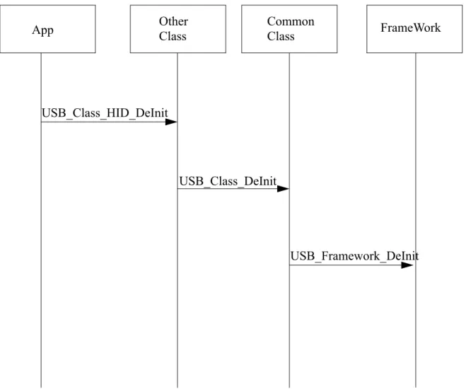
Figure 3-4. Sequence diagram for stack de-initiation
3.2.3
Transmission flow
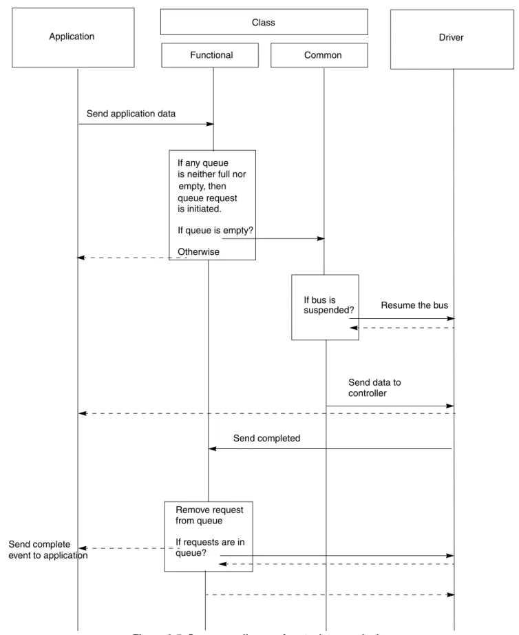
Figure 3-5 describes stack transmission flow.
App Other Class Common Class FrameWork
USB_Class_HID_DeInit
USB_Class_DeInit
Figure 3-5. Sequence diagram for stack transmission Application Class Functional Common Driver If any queue is neither full nor empty, then queue request Send application data
If bus is
suspended? Resume the bus
Send data to controller Send completed Remove request from queue If requests are in queue? Send complete event to application is initiated. If queue is empty? Otherwise
The application transmits data to the USB host by calling the class driver specific send API. The class driver checks for the current status of the queue. If the queue is full then the function returns with a BUSY status, if there is already an outstanding request that has not been completed yet, it queues the request unless the queue is empty, it prepares to pass the request to the low level driver. As part of the preparation, it checks whether the bus is suspended or not. Incase the bus is suspended, it wakes the bus and the bus then sends the request to the lower layer driver. When the send API operation is completed, the class driver removes the request from the queue and sends the next in queue if it exists.
3.2.4
Reception flow
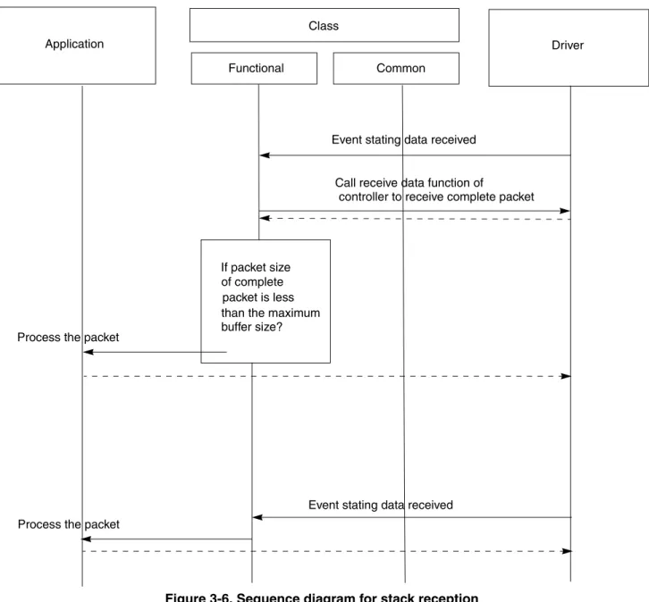
Figure 3-6 below describes stack reception flow.
Figure 3-6. Sequence diagram for stack reception Application Class Functional Common Driver If packet size of complete packet is less than the maximum
Event stating data received
Call receive data function of
controller to receive complete packet
buffer size?
Process the packet
Event stating data received Process the packet
When the controller receives the data on its receiver port, the low level driver sends an event to the class driver. The class driver calls the low level driver to receive the packet in its buffers. If the size of the packet is smaller than the size of the end-point buffer, then the class driver processes the packet immediately. If the size of the packet is greater than the endpoint buffer size, the class driver waits for an event from the low level driver with the complete packet. The class driver processes the packet after it is received.
Chapter 4 Developing New Class Drivers
4.1
Introduction
This chapter provides user methodology for developing new applications based on existing available class drivers. It also describes how a user can develop a new class driver and application using USB low level stack framework.
Support for HID, CDC, and PHDC class drivers is already implemented in the package. Refer Freescale USB Stack Device API Reference Manual (document USBAPIRM.pdf).
Before starting with developing the class drivers, Figure 4-1 shows the current design of the class drivers.
Figure 4-1. Current design of class drivers
The class drivers are divided into three modules.
• Framework Module—The framework module handles all requests to the control end point. It implements all responses to the USB Chapter 9 requests. It interacts with the application to get the USB descriptor information.
• Common Class Module—The common class module contains implementation independent to application specific classes. It handles functions like suspend/resume, reset, stall, and SOF that needs to be present for all classes.
• Class Specific Module—This module implements class specific functionality. It implements all interactions with non control end points. The data sent and received on these end points are class specific. This module also implements the class specific requests on the control end point.
Application Class Specific Module Common Class Module Framework Module
Low Level Driver
Class API
Device API
Although, a developer could start developing a new class by using the device API and implementing complete functionality. However, it is recommended to use a similar design like the existing classes and reusing some pre-existing common modules like the common class module and the framework module.
4.2
Steps for developing new class drivers
This section explains how a user can develop new class drivers based on an existing USB low level device framework and common class specific module.
4.2.1
Directory structure
Define the class API as shown in Figure 4-1. The application must use this interface to call the class driver. These can be similarly defined like the pre-existing hid and phdc classes. The interface definitions are in usb_hid.h and usb_phdc.h and so on in the /source/class directory.
Figure 4-2. Class Directory Structure
Staying in the same directory creates a class specific module as shown in Figure 4-1. This can be done by creating two files namely usb_<newclass>.c and usb_<newclass>.h. Implement the class specific code in the .c file and put the interface definition in the .h file.
4.2.2
Class initialization
Implement class initialization function. This function initializes class specific data structures. This function also initializes USB Common Class Module and USB Device Framework through
USB_Class_Init() and USB_Device_Init() respectively.
Typically, three callbacks are provided by an application for interfacing with class driver. • Class callback (to receive various USB bus events)
• To support vendor specific requests.
Pseudo Code:
uint_8 USB_Class_XYZ_Init (
uint_8 controller_ID, /* [IN] Controller ID */ USB_CLASS_CALLBACK class_callback, /* [IN] Class Callback */
USB_REQ_FUNC vendor_req_callback, /* [IN] Vendor Request Callback */
USB_CLASS_SPECIFIC_HANDLER_FUNC param_callback /* [IN] Class Specific requests Callback */
) {
uint_8 index;
USB_ENDPOINTS *ep_desc_data = (USB_ENDPOINTS *) USB_Desc_Get_Endpoints(controller_ID); /* Initialize the device layer*/
USB_Device_Init(controller_ID, ep_desc_data->count+1); /* Initialize the generic class functions */
USB_Class_Init(controller_ID,
USB_Class_XYZ_Event, USB_Class_XYZ_Requests); <Class Specific Initialization code goes here > /* save the XYZ class callback pointer */ g_class_callback = class_callback;
/* save the vendor request callback pointer */ g_vendor_req_callback = vendor_req_callback;
/* Save the callback to ask application for class specific params*/
g_param_callback = param_callback; }
4.2.3
Class callback routine
This routine is called by USB Common Class Module to notify class driver about various USB events. The following events are notified:
• USB Bus Reset
This event is notified when USB Bus Reset is detected by Device Controller. The class driver should reset its data structure after receiving this event. Depending on the class requirement, the event can be propagated to application through a callback.
• Enumeration Complete
This event is notified when USB Bus Enumeration is completed and Set Configuration call is received from USB host. Class driver should now initialize all the endpoints
(USB_Device_Init_EndPoint()) other than control endpoint. It should also register callback functions (USB_Device_Register_Service()) to handle endpoint events and set Endpoint Status as “idle” (USB_Device_Set_Status()).
• Configuration Change
This event is notified when SET CONFIGURATION call is received from USB host. Once this event is received, Enumeration Complete event is notified to the class driver. • Data Send Complete
This event is notified when data is sent through an endpoint. • Data Received
Pseudo Code:
static void USB_Class_XYZ_Event (
uint_8 controller_ID, /* [IN] Controller ID */ uint_8 event, /* [IN] Event Type */
void* val /* [IN] Pointer to configuration Value */ ) { uint_8 index; if(event == USB_APP_ENUM_COMPLETE) { uint_8 count = 0;
/* get the endpoints from the descriptor module */ USB_ENDPOINTS *ep_desc_data = (USB_ENDPOINTS *) USB_Desc_Get_Endpoints(controller_ID);
/* intialize all non control endpoints */ while(count < ep_desc_data->count) { USB_EP_STRUCT_PTR ep_struct= (USB_EP_STRUCT_PTR)&ep_desc_data->ep[count]; (void)USB_Device_Init_EndPoint(controller_ID, ep_struct, TRUE);
/* register callback service for the endpoint */ (void)USB_Device_Register_Service(controller_ID, (uint_8)(USB_SERVICE_EP0+ep_struct->ep_num), USB_Class_XYZ_Service_Endpoint);
/* set the EndPoint Status as Idle in the device layer */ (void)USB_Device_Set_Status(controller_ID,
(uint_8)(USB_STATUS_ENDPOINT | <ENDPOINT NUMBER> | (ep_struct->direction << USB_COMPONENT_DIRECTION_SHIFT)), USB_STATUS_IDLE);
count++; }
}
else if(event == USB_APP_BUS_RESET) {
<Re-Initialize Class Specific Data Structure > }
if(g_class_callback != NULL) {
/* notify the application of the event */ g_class_callback(controller_ID, event, val); }
4.2.4
Class request routine
This routine is called by USB Common Class Module. It handles class specific and vendor specific requests received from USB host. Vendor Specific requests are sent to Application using Vendor Specific application callback function already initialized with the class driver.
Pseudo Code:
static uint_8 USB_Class_XYZ_Requests (
uint_8 controller_ID, /* [IN] Controller ID */ USB_SETUP_STRUCT * setup_packet, /*[IN] Setup packet */ uint_8_ptr *data, /* [OUT] Data to be send back */ USB_PACKET_SIZE *size /* [OUT] Size to be returned*/ )
{
uint_8 index;
uint_8 status = USBERR_INVALID_REQ_TYPE;
uint_8 rpt_buf[REPORT_SIZE];/* buffer to send in case of get report req */ *((uint_32_ptr)rpt_buf) = 0;
if((setup_packet->request_type & USB_REQUEST_CLASS_MASK) == USB_REQUEST_CLASS_CLASS)
{
/* class request so handle it here */ <Class Specific Code goes here> if(g_param_callback != NULL) {
/* notify the application of the class request. Give control to the application */
status = g_param_callback(setup_packet->request, setup_packet->value, data, size); } }
else if((setup_packet->request_type & USB_REQUEST_CLASS_MASK) ==
USB_REQUEST_CLASS_VENDOR) {
/* vendor specific request */ if(g_vendor_req_callback != NULL) { status = g_vendor_req_callback(controller_ID, setup_packet,data, size); } } return status; }
4.2.4.1 Endpoint service routine
This routine is called by USB Low Level Device Framework when data is sent or received on an endpoint. This routine is registered with the Low Level Device Framework by Class Driver during endpoint initialization.
Pseudo Code:
static void USB_Class_XYZ_Service_Endpoint (
PTR_USB_EVENT_STRUCT event /* [IN] Pointer to USB Event Structure */ ) { APP_DATA_STRUCT bulk_data; bulk_data.data_ptr = event->buffer_ptr; bulk_data.data_size = event->len; if(g_class_callback != NULL) { if(event->errors != 0) {
<Class Specific Error Handling Code goes here> g_class_callback(event->controller_ID, USB_APP_ERROR, (uint_8*)(&(event->errors))); } else { if(event->direction == USB_RECV) {
< Class Specific Data Receive Handling Code goes here> g_class_callback(event->controller_ID, USB_APP_DATA_RECEIVED, (void*)&bulk_data); } else {
< Class Specific Data Send Complete Handling Code goes here> g_class_callback(event->controller_ID, USB_APP_DATA_SEND_COMPLETE, (void*)&bulk_data); } } } }
Chapter 5 Developing Applications
5.1
Introduction
This chapter discusses the functions used to develop applications based on the existing classes.
5.2
Application interfaces
The interfaces of the existing classes are defined keeping in mind that the application must be kept as independent as possible from the lower layer class drivers as well as drivers.
The interface definition between the application and classes is made up of the calls shown in Table 5-1.
5.3
Developing an Application
Perform these steps to develop a new application:
1. Make a new application directory under /device/app directory. The new application directory is made to make the new application.
2. Copy the following files from the similar pre-existing applications. — main.c
— usb_descriptor.c — usb_descriptor.h — user_config.h
Table 5-1. API calls
API Call Description
Class Initialize This API is used to initialize the class that in turn initializes not only the class but also initializes the lower driver layers.
Send Data This API is used by the application to send the data to the host system. It is not recommended to make this call in a non-interrupt context.
Event Callback All events on the bus are propagated to the application using the event callback. The data received on the bus is also propagated to the application using the event callback.
USB Vendor Specific Callback
This is an optional callback and is not mandatory for the application to support it. This callback is used to propagate any vendor specific request that the host system might have sent. Periodic Task This is an API call by the application to the class, so that it can
complete some tasks that it may want to execute in non-interrupt context.
Change these files to suit your application. The usb_descriptor.c and usb_descriptor.h files contain the descriptors for USB that are dependent on the application and the class driver. The
user_config.h contains configuration options. The main.c file contains the initial code for the device. If the device is changed, this file must also be modified accordingly.
3. Create the CodeWarrior directory where the project files for the new application can be created. 4. Create a new file for creating the main application function and the callback function as defined
above. In Figure 5-1, the new_app.c and new_app.h are used for the same purpose.
Figure 5-1. New application directory
• usb_descriptor.c
This file contains USB Framework Module interface. It also contains various descriptors defined by USB Standards like, device descriptor, configuration descriptor, string descriptor and other class specific descriptors that are provided to Framework Module when requested. For customization, user can modify these variables and function implementations to suit the requirement.
a) Variables
The list below shows user modifiable variables for an already implemented class driver. The user should also modify corresponding MACROs defined in usb_descriptor.h file. For example, to save precious RAM space in S08 devices, constant variables are stored in ROM. – usb_desc_ep
This is an array of endpoint structures. Endpoint structure describes the property of endpoint like, endpoint number, size, direction, type, and so on. This array should contain all the mandatory endpoints defined by USB class specifications.
Sample code implementation of usb_desc_ep for HID class is given below: const USB_ENDPOINTS usb_desc_ep =
{ HID_DESC_ENDPOINT_COUNT, { HID_ENDPOINT, USB_INTERRUPT_PIPE, USB_SEND,
HID_ENDPOINT_PACKET_SIZE,<---User Modifiable
}
< User can add other endpoints depending on class requirement >
– g_device_descriptor
This variable contains USB Device Descriptor.
Sample code implementation of device descriptor for HID class is given below: uint_8 const g_device_descriptor[DEVICE_DESCRIPTOR_SIZE] =
{
DEVICE_DESCRIPTOR_SIZE, /* "Device Descriptor Size */ USB_DEVICE_DESCRIPTOR, /* "Device" Type of descriptor */ 0x00, 0x02, /* BCD USB version */ 0x00, /* Device Class is indicated in the interface descriptors */
0x00, /* Device Subclass is indicated in the interface descriptors */ 0x00, /* Device Protocol */ CONTROL_MAX_PACKET_SIZE, /* Max Packet size */
0x04,0x25, <---User Modifiable /* Vendor ID */ 0x00,0x01, <---User Modifiable /* Product ID */ 0x02,0x00, /* BCD Device version */ 0x01, <---User Modifiable /* Manufacturer string index */ 0x02, <---User Modifiable /* Product string index */ 0x00, <---User Modifiable /* Serial number string index */ 0x01 /* Number of configurations */
};
– g_config_descriptor
This variable contains USB Configuration Descriptor.
Sample code implementation of configuration descriptor for HID class is given below: uint_8 const g_config_descriptor[CONFIG_DESC_SIZE] =
{
CONFIG_ONLY_DESC_SIZE, /* Configuration Descriptor Size - always 9
bytes */
USB_CONFIG_DESCRIPTOR, /* "Configuration" type of descriptor */ CONFIG_DESC_SIZE, 0x00, /* Total length of the
Configuration descriptor */
1, /* NumInterfaces */
1, /* Configuration Value */
0, /* Configuration Description String Index*/
BUS_POWERED|SELF_POWERED|
(REMOTE_WAKEUP_SUPPORT<<REMOTE_WAKEUP_SHIFT),
/* S08/CFV1/CFV2 are both self powered (its compulsory to set bus powered)*/ /*Attributes.support RemoteWakeup and self power*/
0x32, <---User Modifiable /* Current draw from bus */
/* Interface Descriptor */ IFACE_ONLY_DESC_SIZE, USB_IFACE_DESCRIPTOR, 0x00, 0x00, HID_DESC_ENDPOINT_COUNT, 0x03, 0x01, 0x02, 0x00, /* HID descriptor */ HID_ONLY_DESC_SIZE,
USB_HID_DESCRIPTOR, 0x00,0x01, 0x00, 0x01, 0x22, 0x34,0x00, /*Endpoint descriptor */ ENDP_ONLY_DESC_SIZE, USB_ENDPOINT_DESCRIPTOR, HID_ENDPOINT|(USB_SEND << 7), USB_INTERRUPT_PIPE,
HID_ENDPOINT_PACKET_SIZE, 0x00, <---User Modifiable
0x0A
};
– String Descriptors
Users can modify string descriptors to customize their product. String descriptors are written in UNICODE format. An appropriate language identification number is specified in USB_STR_0. Multiple language support can also be added.
Sample code implementation of string descriptors for HID class application is given below: uint_8 const USB_STR_0[USB_STR_0_SIZE+USB_STR_DESC_SIZE] =
{
sizeof(USB_STR_0), USB_STRING_DESCRIPTOR, 0x09,
0x04/*equiavlent to 0x0409*/
<User can add other language support descriptor here> };
uint_8 const USB_STR_1[USB_STR_1_SIZE+USB_STR_DESC_SIZE] = {
sizeof(USB_STR_1), USB_STRING_DESCRIPTOR,
<User Modifiable Manufacturer Name in UNICODE> 'F',0, 'R',0, 'E',0, 'E',0, 'S',0, 'C',0, 'A',0, 'L',0, 'E',0, ' ',0, 'S',0, 'E',0, 'M',0, 'I',0, 'C',0, 'O',0, 'N',0, 'D',0, 'U',0, 'C',0, 'T',0,
'O',0, 'R',0, ' ',0, 'I',0, 'N',0, 'C',0, '.',0 };
uint_8 const USB_STR_2[USB_STR_2_SIZE+USB_STR_DESC_SIZE] = {
sizeof(USB_STR_2), USB_STRING_DESCRIPTOR,
<User Modifiable Product Name in UNICODE> ' ',0, ' ',0, 'J',0, 'M',0, ' ',0, 'H',0, 'I',0, 'D',0, ' ',0, 'D',0, 'E',0, 'M',0, 'O',0, ' ',0 };
uint_8 const USB_STR_n[USB_STR_n_SIZE+USB_STR_DESC_SIZE] = { sizeof(USB_STR_n), USB_STRING_DESCRIPTOR, 'B',0, 'A',0, 'D',0, ' ',0, 'S',0, 'T',0, 'R',0, 'I',0, 'N',0, 'G',0, ' ',0, 'I',0, 'N',0, 'D',0, 'E',0, 'X',0 };
uint_8 const g_string_desc_size[USB_MAX_STRING_DESCRIPTORS+1] = {
sizeof(USB_STR_0), sizeof(USB_STR_1), sizeof(USB_STR_2),
<User can add other string descriptors sizes here> sizeof(USB_STR_n)
};
uint_8_ptr const g_string_descriptors[USB_MAX_STRING_DESCRIPTORS+1] = {
(uint_8_ptr const) USB_STR_0, (uint_8_ptr const) USB_STR_1, (uint_8_ptr const) USB_STR_2,
<User can add other string descriptors here> (uint_8_ptr const) USB_STR_n
}; USB_ALL_LANGUAGES g_languages = { USB_STR_0, sizeof(USB_STR_0), { (uint_16 const)0x0409,
(const uint_8 **)g_string_descriptors, g_string_desc_size
}
<User can add other language string descriptors here> };
– Standard Descriptor Table
Users can modify standard descriptor table to support additional class specific descriptors and vendor specific descriptors.
Sample implementation below is shown for HID Class application.
USB_PACKET_SIZE const g_std_desc_size[USB_MAX_STD_DESCRIPTORS+1] = { 0, DEVICE_DESCRIPTOR_SIZE, CONFIG_DESC_SIZE, 0, /* string */ 0, /* Interface */ 0, /* Endpoint */ 0, /* Device Qualifier */ 0, /* other speed config */
<Other Descriptor Sizes goes here> REPORT_DESC_SIZE
};
uint_8_ptr const g_std_descriptors[USB_MAX_STD_DESCRIPTORS+1] = { NULL, (uint_8_ptr)g_device_descriptor, (uint_8_ptr)g_config_descriptor, NULL, /* string */ NULL, /* Interface */ NULL, /* Endpoint */
NULL, /* Device Qualifier */ NULL, /* other speed config*/ <Other Descriptor pointers go here> Sample HID Class Report Desc->
(uint_8_ptr)g_report_descriptor };
– g_valid_config_values
This variable contains valid configurations for a device. This value remains fixed for a device.
uint_8 const g_valid_config_values[USB_MAX_CONFIG_SUPPORTED+1]={0,1}; – g_alternate_interface
This variable contains valid alternate interfaces for a given configuration. Sample implementation uses a single configuration. If user is implementing additional alternate interfaces then USB_MAX_SUPPORTED_INTERFACES macro (usb_descriptor.h) should be changed accordingly.
static uint_8 g_alternate_interface[USB_MAX_SUPPORTED_INTERFACES]; b) Interfaces
The following interfaces are required to be implemented by Application in usb_descriptor.c. These interfaces are called by low level USB stack and class drivers. Refer to Freescale USB Stack Device API Reference Manual (document USBAPIRM.pdf) for details regarding interface functions along with sample implementation. Also, refer to usb_descriptor.c and
usb_descriptor.h files in device\app\hid for reference. – USB_Desc_Get_Descriptor
This interface function is invoked by USB Framework. This call is made when Framework receives GET_DESCRIPTOR call from Host. Mandatory descriptors that an application is required to implement are:
– Device Descriptor – Configuration Descriptor
– Class Specific Descriptors (For example, for HID class implementation, Report Descriptor and HID Descriptor)
Apart from the mandatory descriptors, an application should also implement various string descriptors as specified by the Device Descriptor and other configuration descriptors. Sample code for HID class application is given below.
uint_8 USB_Desc_Get_Descriptor(
uint_8 controller_ID, /* [IN] Controller ID */
uint_8 type, /* [IN] Type of descriptor requested */ uint_8 str_num, /* [IN] String index for string descriptor */ uint_16 index, /* [IN] String descriptor language Id */ uint_8_ptr *descriptor, /* [OUT] Output descriptor pointer */ USB_PACKET_SIZE *size /* [OUT] Size of descriptor returned */ )
{
#pragma unused (controller_ID) switch(type)
{
<Class Specific Descriptor code goes here > case USB_REPORT_DESCRIPTOR:
{
type = USB_MAX_STD_DESCRIPTORS;
*descriptor = (uint_8_ptr)g_std_descriptors [type]; *size = g_std_desc_size[type];
} break;
case USB_HID_DESCRIPTOR: {
type = USB_CONFIG_DESCRIPTOR ;
*descriptor = (uint_8_ptr)(g_std_descriptors [type]+ CONFIG_ONLY_DESC_SIZE+IFACE_ONLY_DESC_SIZE); *size = HID_ONLY_DESC_SIZE; } break; case USB_STRING_DESCRIPTOR: { if(index == 0) {
/* return the string and size of all languages */ *descriptor = (uint_8_ptr)g_languages. languages_supported_string; *size = g_languages.languages_supported_size; } else { uint_8 lang_id = 0;
uint_8 lang_index = USB_MAX_LANGUAGES_SUPPORTED; for(;lang_id < USB_MAX_LANGUAGES_SUPPORTED; lang_id++) {
/* check whether we have a string for this language */
if(index ==
g_languages.usb_language[lang_id].language_id) {
/* check for max descriptors */
if(str_num < USB_MAX_STRING_DESCRIPTORS) {
/* setup index for the string to be returned */ lang_index = str_num; } break; } }
/* set return val for descriptor and size */ *descriptor = (uint_8_ptr)g_languages.usb_language[lang_id]. lang_desc[lang_index]; *size = g_languages.usb_language[lang_id]. lang_desc_size[lang_index]; } } break; default : if (type < USB_MAX_STD_DESCRIPTORS) {
/* set return val for descriptor and size*/
/* if there is no descriptor then return error */ if(*descriptor == NULL) { return USBERR_INVALID_REQ_TYPE; } *size = g_std_desc_size[type]; }
else /* invalid descriptor */ { return USBERR_INVALID_REQ_TYPE; } break; } return USB_OK; } – USB_Desc_Get_Endpoints
This interface function is called from class driver. This function returns a pointer to USB_ENDPOINT structure. This structure describes the characteristics of Non Control Endpoint, for example. endpoint number, type, direction, and size or any other endpoint characteristic required by class driver implementation.
Sample implementation is given below. void* USB_Desc_Get_Endpoints (
uint_8 controller_ID /* [IN] Controller ID */ )
{
#pragma unused (controller_ID)
return (void*)&usb_desc_ep; }
– USB_Desc_Get_Interface
This interface function invoked by USB Framework. This function returns a pointer to alternate interface for the specified interface. This routine is called when USB Framework receives GET_INTERFACE request from Host.
Sample code for single configuration HID class is given below. uint_8 USB_Desc_Get_Interface
(
uint_8 controller_ID, /* [IN] Controller ID */ uint_8 interface, /* [IN] Interface number */
uint_8_ptr alt_interface /* [OUT] Output alternate interface */ )
{
#pragma unused (controller_ID)
/* if interface valid */
if(interface < USB_MAX_SUPPORTED_INTERFACES)
{
<User can modify this to support multiple configurations>
/* get alternate interface*/
*alt_interface = g_alternate_interface[interface];
return USB_OK;
return USBERR_INVALID_REQ_TYPE; }
– USB_Desc_Remote_Wakeup
This interface function invoked by USB Framework. If the application supports remote wakeup then this function return TRUE otherwise FALSE. If the application supports remote wakeup, then USB Device Descriptor should support this capability. If user does not support remote wakeup, then set REMOTE_WAKEUP_SUPPORT should be set to 0 in usb_descriptor.h.
Sample code is given below.
boolean USB_Desc_Remote_Wakeup (
uint_8 controller_ID /* [IN] Controller ID */ )
{
#pragma unused (controller_ID)
return REMOTE_WAKEUP_SUPPORT;
}
– USB_Desc_Set_Interface
This interface function is called from USB Framework. This function sets an alternate interface for specified interface. This routine is called when USB Framework receives SET_INTERFACE request from the host.
Sample code for single configuration HID class is given below. uint_8 USB_Desc_Set_Interface
(
uint_8 controller_ID, /* [IN] Controller ID */ uint_8 interface, /* [IN] Interface number */
uint_8 alt_interface /* [IN] Input alternate interface */ )
{
#pragma unused (controller_ID) /* if interface valid */
if(interface < USB_MAX_SUPPORTED_INTERFACES) {
<User can modify this to support multiple configurations> /* set alternate interface*/
g_alternate_interface[interface] = alt_interface; return USB_OK; } return USBERR_INVALID_REQ_TYPE; } – USB_Desc_Valid_Configation
This interface function is called from USB Framework. This function returns if the configuration is valid or not. This routine is called when USB Framework receives SET_CONFIGURATION request from the host.
boolean USB_Desc_Valid_Configation( (
uint_8 controller_ID, /*[IN] Controller ID */ uint_16 config_val /*[IN] Configuration value */
) {
#pragma unused (controller_ID)
uint_8 loop_index=0;
/* check with only supported val right now */ while(loop_index < (USB_MAX_CONFIG_SUPPORTED+1)) { if(config_val == g_valid_config_values[loop_index]) { return TRUE; } loop_index++; } return FALSE; } – USB_Desc_Valid_Interface
This interface function is called from class driver to validate if the interface is valid or not. This function returns TRUE if interface is valid, otherwise FALSE.
Sample code for single configuration HID class is given below. boolean USB_Desc_Valid_Interface
(
uint_8 controller_ID, /*[IN] Controller ID */ uint_8 interface /*[IN] Target interface */
) {
#pragma unused (controller_ID)
uint_8 loop_index=0;
<User can modify this to support multiple configurations> /* check with only supported val right now */
while(loop_index < USB_MAX_SUPPORTED_INTERFACES) { if(interface == g_alternate_interface[loop_index]) { return TRUE; } loop_index++; } return FALSE; }
Apart from above interfaces mandated by USB Low Level Framework, the application must also implement various callback functions to receive events from USB class driver. These interface functions are implemented in new_app.c file.
— Class Callback function
This function is used by class driver to inform application about various USB Bus Events. The application can use these events to perform event specific functionalities. The implementation of this callback function is governed by class driver specification.
Pseudo Code:
void USB_App_Class_Callback (
uint_8 controller_ID,/* [IN] Controller ID */ uint_8 event_type, /* [IN] value of the event*/ void* val /* [IN] gives the configuration value*/ )
{
if(event_type == USB_APP_BUS_RESET) {
/* USB Bus Reset */
<Application Specific Code goes here> }
else if(event_type == USB_APP_ENUM_COMPLETE) {
/* Enumeration is complete */
<Application Specific Code goes here> }
return; }
— Vendor Request Callback
This optional argument allows application to support any vendor specific USB requests received from USB host. This function allows application developer to enhance existing class implementation by adding vendor specific functionality.
Pseudo Code:
uint_8 USB_App_Vendor_Request_Callback (
uint_8 request, /* [IN] request type */
/* [IN] Pointer to Setup Packet */
USB_SETUP_STRUCT *setup,
uint_8_ptr* data, /* [OUT] pointer to the data */ USB_PACKET_SIZE* size/* [OUT] size of the transfer */
) {
uint_8 status = USB_OK;
uint_8 request = setup-> request;
switch(request)
{
< Vendor Specific Requests are handled here >
case <VENDOR_REQUEST1> :
*data = <Pointer to Data to be sent>
*size = <size of Data to be sent>
break;
case <VENDOR_REQUEST2>:
*data = <Pointer to Data to be sent>
*size = <size of Data to be sent>
break;
: : :
default:
< UNHANDLED Vendor Specific Requests Application code goes here>
break;
}
return status;
}
— Class Specific Request Callback
Implementation of this function is governed by Class Driver Design. The design and implementation details are however beyond the scope.
Pseudo Code:
uint_8 USB_App_Class_Spec_Request_Callback (
uint_8 request, /* [IN] request type */ uint_16 value, /* [IN] report type and ID */ uint_8_ptr* data, /* [OUT] pointer to the data */ USB_PACKET_SIZE* size/* [OUT] size of the transfer */ )
{
uint_8 status = USB_OK; *size = 0;
/* handle the class request */ switch(request)
{
< Class Specific Requests are handled here > case <REQUEST1>:
*data = <Pointer to Data to be sent>
*size = <size of Data to be sent>
break;
case <REQUEST2>:
*data = <Pointer to Data to be sent>
*size = <size of Data to be sent>
break;
: : :
default:
< UNHANDLED Class Specific Requests Application code goes here>
status = USBERR_INVALID_REQ_TYPE; break; } return status; } • usb_descriptor.h
This file is mandatory for the application to implement. Framework and class drivers include this file for function prototype definitions and data structures described in usb_descriptor.c. User modifying usb_descriptor.c should also modify MACROs in this file as well.
• user_config.h
This file is required to define various compile time macros. These parameters are essential for successful compilation of source code.
– LONG_SEND_TRANSACTION — This macro is defined for classes that have to send data more than the endpoint size over USB bus. It allows Low Level Device Framework to use split transaction for sending data over USB bus.
– LONG_RECIEVE_TRANSACTION — This macro is defined for classes that have to receive data more than the endpoint size over USB bus. It allows Low Level Device Framework to use split transaction for receiving data over USB bus.
– USB_PACKET_SIZE — This macro defines maximum transfer packet size of USB Data Transaction.
– MAX_TIMER_OBJECTS — This macro defines number of timer objects required by application.
– TIMER_CALLBACK_ARG — This macro if defined invokes timer callbacks with an application specified argument.
– DOUBLE_BUFFERING_USED — For S08 devices, if application is making use of endpoint 5 and 6 (Double Buffered) then this macro has to be defined. For CFV1 and CFV2 devices, this macro is not required, as all the endpoints are double buffered.
5. After the functionality has been implemented, use the steps defined in A.1.2, “Building the Application with CodeWarrior 6 and CodeWarrior 7” and A.1.3, “Running the Application with CodeWarrior 6 and CodeWarrior 7” to build and run the application.
5.4
Application design
This section discusses the application design. The application is made up of the main application function and the callback function.
5.4.1
Main Application Function
The main application function uses the following C code: void TestApp_Init(void)
{
uint_8 error; DisableInterrupts;
<Application Specific Initialization Code goes here> /* Initialize the USB Class Driver interface */ <USB Class Initialization Call>
error = USB_Class_XYZ_Init(0, USB_App_Callback, NULL, USB_App_Param_Callback); EnableInterrupts; while (TRUE) { __RESET_WATCHDOG();
<Application Specific Code goes here> new_app_task();
}/* Endwhile */ }
5.4.2
Callback Function
The callback function uses the following C code:
void USB_App_Callback(uint_8 controller_ID, uint_8 event_type, void* val) {
if(event_type == USB_APP_BUS_RESET) {
<Application Specific Code goes here> }
else if(event_type == USB_APP_ENUM_COMPLETE) {
/* if enumeration is complete */ <Application Specific Code goes here> }
else if(event_type == USB_APP_ENUM_ERROR) {
<Application Specific Code goes here> }
return; }
Appendix A Working with the Software
A.1
Introduction
This chapter gives you insight on how to use the Freescale USB Stack software. The following sections are described in this chapter:
• Preparing the setup • Building the application • Running the application
Knowledge of CodeWarrior IDE will be helpful to understand this section. While reading this chapter, practice the steps mentioned.
To take you through this chapter, the HID mouse application for the MC9S08JM60 is used as an example. For preparing the setup, building the application, and running the application the following devices— Kinetis, HC(S)08, ColdFire v1, and ColdFire V2—are used as an example.
A.1.1
Preparing the setup
A.1.1.1 Software setup
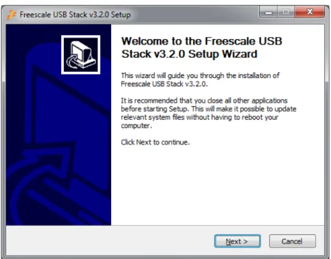
1. Double-click the Freescale_USB_Stack_v[current version].exe installer executable file.
2. The Freescale USB Stack Setup window appears. The following example shows the demonstration for USB Stack installation. You can follow the same instructions for new versions.
Example:
Figure A-1. Freescale USB Stack setup wizard
2. In Figure A-2, click on the I Agree button to accept the license agreement.
Figure A-2. Freescale USB Stack setup license agreement
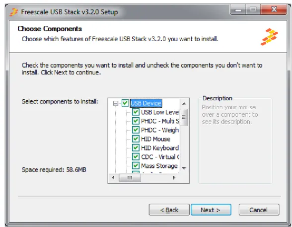
3. In Figure A-3, select USB low level stack and other class components to install and click on the Next button.
Figure A-3. Freescale USB Stack components
4. In Figure A-4, select the location of the folder where you require to install the Freescale USB Stack software and click on the Install button.
Figure A-4. Freescale USB Stack installation folder location
5. Click on the Finish button to successfully complete the Freescale USB Stack Setup Wizard.
Launching Freescale USB Stack project
Click Start > Programs > Freescale USB Stack > Source to launch the project.
Figure A-6. Freescale USB Stack source program for launch
A.1.1.2 Hardware setup
• Make the connections as shown in Figure A-7. Here for hardware setup S08 is used as an example.
Figure A-7. S08 USB setup Host Systems
running Windows XP
Host System running CodeWarrior USB for Power and CodeWarrior Demo JM board USB Demo Connection
— Make the first USB connection between the personal computer where the software is installed and the DemoJM board where the silicon is mounted. This connection is required to provide power to the board and downloading image to the flash.
— Make the second connection between the DemoJM board and the personal computer where the demo is run.
NOTE
Although, we have used two personal computers in Figure A-7, in reality you may achieve the same result by a single personal computer with two or more USB ports.
A.1.2
Building the Application with CodeWarrior 6 and CodeWarrior 7
The software for S08 and CFV1 is built with CodeWarrior 6.3. In addition, the software for CFV2 is built with CodeWarrior 7.2. Therefore, it contains application project files that can be used to build the project. Before starting the process of building the project, make sure CodeWarrior 6.3 is installed on your computer.
To build the S08 project:
1. Navigate to the project file and open the s08usbjm60.mcp project file in CodeWarrior IDE.
Figure A-8. Open s08usbjm60.mcp project file
2. After you have opened the project, the following window appears. To build the project, click the button as shown in Figure A-9.
Code Warrior HID JM60 project file
Figure A-9. Build s08usbjm60.mcp project
3. After the project is built, the code and data columns must appear filled across the files.
NOTE
The above procedure can be used to build CFV1 and CFV2 projects also.
A.1.3
Running the Application with CodeWarrior 6 and CodeWarrior 7
Refer to the board documentation and CodeWarrior manual for details on how to program the flash memory on the evaluation board used. The following steps are presented as an example about how to run the HID mouse application with DemoJM60 board using a P&E-micro debugger.
1. To run the application, click the button as shown in Figure A-10.
Figure A-10. Running the application
2. The dialog box in Figure A-11 appears. Click on the Connect (Reset) button to connect to hardware as shown in Figure A-11.
Figure A-11. Connection Manager
3. The pop-up in Figure A-12 appears. Click on the Yes button to load the built image to the JM60 flash.
Figure A-12. Erase and Program Flash pop-up
4. The pop-up in Figure A-13 appears to erase and program the built image to the JM60 flash.
Click to connect to DemoJM
Figure A-13. Image Programmed in Flash
5. After the image is programmed in the flash, the debugger window as shown in Figure A-14 appears. Click on the Green Arrow as shown in Figure A-14 to run the programmed image.
Figure A-14. Simulator and Real-Time Debugger
A.1.4
Building and Running the Application with CodeWarrior 10
The software for Kinetis k40, S08, CFV1 and CFV2 targets is available to be build, download and debug using the CodeWarrior 10 MCU.
Before starting the process of building the project, make sure CodeWarrior 10 MCU is installed on your computer.
To build the (for example Kinetis k40/S08/CFV1/CFV2) project:
2. Open the project by dragging the .project file and dropping it into the CodeWarrior 10 project space.
3. After you have opened the project, the following window appears. To build the project choose "Build Project" from the Project menu.
4. To run the application, first locate the S08USBJM60 Flash.launch conficuration in the current project space. Right-click it and choose Debug As > 1 S08USBJM60 Flash as in the window below.
5. After the image is programmed in the flash, the debugger window as shown in the next figure appears. Click on the Green arrow in the Debug tab to run the image.
A.2
Uninstall Freescale USB Stack Software
1. From your computer, click Start > Settings > Control Panel > Add or Remove Programs.
Figure 5-2. Add or Remove Programs launch from Control Panel
2. The following example shows the demonstration for uninstalling Freescale USB Stack. You can follow the same instructions for new versions.
Example:
1. In the Windows Control Panel “Add/Remove Programs Tool, select Freescale USB Stack and click on the Change/Remove button.
2. The uninstall confirmation message appears. Click on the Yes button to uninstall.
Figure A-15. Freescale USB Stack Uninstall confirmation message